EP1524492B1 - Apparat für dreidimensionale Messungen - Google Patents
Apparat für dreidimensionale Messungen Download PDFInfo
- Publication number
- EP1524492B1 EP1524492B1 EP04256285A EP04256285A EP1524492B1 EP 1524492 B1 EP1524492 B1 EP 1524492B1 EP 04256285 A EP04256285 A EP 04256285A EP 04256285 A EP04256285 A EP 04256285A EP 1524492 B1 EP1524492 B1 EP 1524492B1
- Authority
- EP
- European Patent Office
- Prior art keywords
- pixels
- dimensional
- image
- measurement apparatus
- detected
- Prior art date
- Legal status (The legal status is an assumption and is not a legal conclusion. Google has not performed a legal analysis and makes no representation as to the accuracy of the status listed.)
- Expired - Fee Related
Links
Images

Classifications
-
- G—PHYSICS
- G01—MEASURING; TESTING
- G01B—MEASURING LENGTH, THICKNESS OR SIMILAR LINEAR DIMENSIONS; MEASURING ANGLES; MEASURING AREAS; MEASURING IRREGULARITIES OF SURFACES OR CONTOURS
- G01B11/00—Measuring arrangements characterised by the use of optical techniques
- G01B11/24—Measuring arrangements characterised by the use of optical techniques for measuring contours or curvatures
- G01B11/25—Measuring arrangements characterised by the use of optical techniques for measuring contours or curvatures by projecting a pattern, e.g. one or more lines, moiré fringes on the object
-
- G—PHYSICS
- G06—COMPUTING; CALCULATING OR COUNTING
- G06T—IMAGE DATA PROCESSING OR GENERATION, IN GENERAL
- G06T7/00—Image analysis
- G06T7/50—Depth or shape recovery
- G06T7/521—Depth or shape recovery from laser ranging, e.g. using interferometry; from the projection of structured light
Definitions
- the present invention relates to a three-dimensional measurement apparatus in which slit light or pseudo slit light simulatedly created by scanning spot light is irradiated onto an object to form a linear bright portion, the bright portion is detected by image capturing means, and information related to three-dimensional position of the object is obtained from the position of the bright portion in the captured image.
- the three-dimensional measurement apparatus of the present invention is used as being mounted to a robot, for instance.
- a three-dimensional measurement apparatus that recognizes the three-dimensional position, orientation, shape, size, etc. (hereinafter collectively referred to as "three-dimensional position-related information") of a workpiece serves as important basic means for intelligent robots. Since the three-dimensional measurement apparatus is often used by being mounted to a robot, the measurement apparatus is demanded not only to have high accuracy but also to be miniaturized.
- slit light is a generic name including “pseudo slit light created by spot light scanning"
- slit light is a generic name including "pseudo slit light created by spot light scanning”
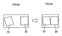
- the measurement apparatus can be miniaturized by decreasing the installation distance between the projector 10 and the photodetector 20, as shown in FIG. 6b.
- the measurement accuracy (especially, the measurement accuracy in the depth direction as seen from the measurement apparatus) is liable to be worsened due to the measurement principle. That is, in the three-dimensional measurement apparatus of the slit light projection type, there are in general conflicting requirements of miniaturizing the apparatus and improving the measurement accuracy. Therefore, and from the viewpoint of compensating demerit due to the miniaturization, the technical art of providing a highly accurate three-dimensional measurement apparatus of the slit light projection type has been strongly demanded.
- JP-A-63 132 107 JP-A-63 132 107, for instance.
- This proposal relates to an object measurement apparatus for measuring the position of a light section line in an image with accuracy higher than the resolution of an image pickup element, and for performing high speed calculation processing to realize a high speed measurement.
- the apparatus disclosed in JP-A-63 132 107 adopts a method in which a luminance variation in a difference image between an original image and an image observed when slit light is irradiated onto a section line is examined in the direction of each scanning line of a camera, and the center position of the slit light for every scanning line is determined by performing weighted mean processing based on a distribution of luminance that is higher than or equal to a certain threshold.
- This invention provides a three-dimensional measurement apparatus capable of ensuring the required measurement accuracy in detecting a bright portion formed by irradiation of slit light, even if detected data is somewhat disturbed by uneven stain on or uneven roughness of a measurement object surface, or the like.
- this invention makes it possible to exclude irreliable detection data so that three-dimensional position-related information can be used for the measurement, even if the detection data is somewhat disturbed by uneven stain on or uneven roughness of a measurement object surface, or the like.
- a three-dimensional measurement apparatus of the present invention obtains information related to three-dimensional position of an object based on detection of a position of a bright portion, which is formed substantially linearly by irradiating slit light or pseudo slit light created by scanning spot light onto the object, in an image of the object captured by image capturing means.
- This three-dimensional measurement apparatus is provided with at least the following means (a)-(c):
- the information related to three-dimensional position of the object may include any one of a three-dimensional position, a three-dimensional posture, a three-dimensional shape and a size of the object.
- the means for determining the allowable range may comprise: means for obtaining an average of the number of brightened pixels per one detection line based on the numbers of brightened pixels counted respectively along the plurality of detection lines; and means for calculating the allowable range based on the obtained average of the number of brightened pixels and minimum and maximum ratios to be respectively multiplied by the determined average of the number of brightened pixels.
- the means for determining the allowable range comprises: means for obtaining an average of the number of brightened pixels per one detection line based on the numbers of brightened pixels counted respectively along the plurality of detection lines; and means for calculating the allowable range based on the obtained average of the number of brightened pixels, a subtractive number to be subtracted from the obtained average of the number of brightened pixels, and an addition number to be added to the obtained average of the number of brightened pixels.
- the minimum and maximum ratios and the subtractive number and the addition numbers may be alterable in a similar manner to that in ordinary setting parameters.
- the present invention it is possible to exclude irreliable data to obtain three-dimensional position-related information that can be used for the measurement, even when slit light is irradiated onto a surface portion of a measurement object that is different in the degree of stain or surface roughness from the remainder and as a result the detected linear bright portion becomes narrow in width or its center position is shifted.
- this invention can suppress a variation in measurement accuracy, and therefore, it is easy to make the installation distance between a projector and a photodetector narrower, thereby miniaturizing the measurement apparatus.
- FIG. 1 is a view showing the overall arrangement of a three-dimensional measurement apparatus according to one embodiment of this invention.
- a projector for projecting slit light (including pseudo slit light obtained by spot light scanning, as previously mentioned) is denoted by reference numeral 10.
- a photodetector 20 is disposed at a slight distance from the projector 10.
- the projector 10 and the photodetector 20 are united into a detection head which is used by being mounted to near an arm distal end of a robot (not shown), for instance.
- the projector and the photodetector are disposed at appropriate places. Even in a case where a robot is used, they may be disposed at appropriate places, without being mounted to the robot.
- the installation distance between the projector 10 and the photodetector 20 is, the more easily the measurement accuracy (especially, measurement accuracy in the depth direction as seen from the projector and the photodetector) can be ensured, but the more difficult it is to meet the need of miniaturization.
- the installation distance is determined by taking the balance into consideration. According to this invention, a variation in the measurement accuracy can advantageously be suppressed, and therefore, it is easier than in the prior art to decrease the installation distance between the projector and the photodetector.
- the projector 10 projects slit light onto a measurement object (for example, a workpiece) 1 in a known manner to thereby form a linear bright portion 2 on a surface of the measurement object 1. Resulting from light projected from the projector 10, scattered light or reflected light is provided from the bright portion 2. The light from the bright portion 2 is detected by the photodetector 20, together with light (scattered light or reflected light resulting from light originally present in the working environment) provided from around the bright portion 2.
- the photodetector 20 is constituted by a digital CCD camera for instance, which is connected to an image processing unit 30 together with the projector 10.
- the image processing unit 30 is adapted to control the on/off action of the projector 10, image pickup of the photodetector 20, subsequent image fetching, etc.
- the robot's position and orientation at the time of measurement are determined so as to select the direction of projection from the projector 20 (or select the three-dimensional orientation of a slit light plane).
- the direction of projection can be adjusted by using an appropriate adjustment mechanism.
- the projector 10 is turned on whereby a linear bright portion 2 is formed such as to pass through an arbitrary to-be-measured portion of the measurement object 1, and an image of the bright portion 2 is picked up by the photodetector 20.
- image data including the bright portion 2 is fetched into the image processing unit 30 and displayed as a detected image on a screen of a monitor display 40 connected to the image processing unit 30.
- the image processing unit 30 has conventionally known construction and functions, and therefore, detailed explanations thereof will be omitted.
- the detected image includes an image of the measurement object 1 denoted by reference numeral 3 and an image of the bright portion 2 denoted by reference numeral 4.
- the bright portion 2 or its image 4 is generally formed into a linear shape or a band-like shape with a certain width, but can include a disturbed part or a disconnected part as will be mentioned below. It is assumed here that the bright portion will be expressed as "linear bright portion” or “linear bright portion image,” etc., even if there is such a disturbance.
- position-related information of the measurement object 1 in the three-dimensional space is determined from the position of the bright portion image 4 in the detected image. That is, the three-dimensional position of one or more points in space, corresponding to one or more points in the bright portion image 4, is determined as detected data. For instance, on the basis of the detected data, the following are measured: three-dimensional position of the measurement object 1 (for example, the position of a characteristic point representative of the measurement object 1); three-dimensional orientation (for instance, the orientation of a surface and the extending direction of a ridge line, which represent the orientation of the measurement object 1); three-dimensional shape (for example, the roundness of a circular profile); size (for example, the diameter of a circular hole); and the like.
- a method for calculating these parameters from the detected data corresponding to the bright portion image 4 has been well known and does not directly relate to this invention, so that detailed explanations thereof will be omitted.
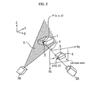
- FIG. 2 is a view for explaining a method for calculating the three-dimensional position of the bright portion 2 from the detected image of the bright portion 2 (bright portion image 4), which is formed by projection of slit light, by using the measurement apparatus shown in FIG. 1. Since this method is well known, only the outline thereof will be explained.
- a light source of the projector 10 when a light source of the projector 10 is turned on, slit light is output from a projecting port (not shown) of the projector 10, whereby a slit light plane 5 is formed that broadens in the shape of fan.
- the bright portion 2 is formed at a position where the slit light plane 5 crosses a surface of the measurement object 1, and is observed as the bright portion image 4 in the detected image obtained by image-picking up with the photodetector 20.
- an arbitrary to-be-measured point which is on the bright portion 2, in other words, which is both on the surface of the measurement object 1 and on the slit light plane 5, is represented by P
- the three-dimensional position of the point P in the real space (three-dimensional space) is represented by (x, y, z).
- the position of a point p in the detected image corresponding to the point P (x, y, z) is represented by (u, v).
- the (u, v) is a coordinate value along Hz and Vt axes (horizontal and vertical axes) of a two-dimensional rectangular coordinate system that is set on the image plane.
- a straight line passing through both the point p and the lens center of the photodetector 20 is referred to as a line of sight 6.
- the position of the line of sight 6 in the real space (an equation describing the straight line for the line of sight 6, or parameter values that are necessary and sufficient to specify such equation) can be determined using calibration data that is stored in advance in the image processing unit 30. Therefore, the position (x, y, z) of the to-be-measured point P in the three-dimensional space is determined as the position of the point of intersection of the slit light plane 5 and the line of sight 6.
- the position of the slit light plane 5 (an equation or parameter values that are necessary and sufficient to specify the equation) can be calculated from calibration data for the projector 10. In case that the projector 10 is mounted to a robot, the position of the slit light plane 5 can be calculated from the calibration data for the projector 10 and current robot position data.
- the method has been described in which the three-dimensional position of the bright portion 2 is calculated by using the measurement apparatus shown in FIG. 1 from the detected image of the bright portion 2 (bright portion image 4) formed by the projection of slit light.
- this method it is the way of recognizing the position (u, v) of the point p in the detected image, which is known in the art, as well as the reliability of the resultant data that are to be considered as significant factors which can greatly vary the measurement accuracy.
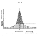
- the actually obtained bright portion image 4 is generally formed as a linear bright region having a width.
- FIG. 3 exemplarily shows, in a bar chart, the luminance data of pixels along a scanning line crossing the bright portion image 4.
- Each bar width of the bar chart corresponds to one pixel.
- a weighted average luminance is first determined along the scanning direction with respect to the pixels for which luminances exceeding the detection threshold have been detected, and then the detected position is calculated. It is tentatively considered that by determining the detected position in the above manner, the detected position of the bright portion image 4 can be determined with accuracy which is more precise than the pixel width, thereby improving the accuracy of three-dimensional position-related information that will be obtained on the basis of the detected position thus determined.
- the above concept is not often the case mainly for the reason that various disturbances or abnormalities are produced in the luminance distribution for pixels along a scanning line. More specifically, when a stain is on the measurement object or when the surface roughness of the measurement object is uneven place by place, the disturbance or unevenness naturally occurs in the reflection characteristic of the measurement object observed when light is projected thereto. As a result, by way of example, in some cases a disturbance occurs in the width (size) of the detected linear bright portion image 4, or disconnection occurs in the bright portion image 4 (there are no pixels whose luminance exceed the threshold), or the luminance distribution along a scanning line is split into two or more (resulting in a plurality of luminance peaks).
- the slit light projected onto the measurement object 1 glares and is broadened in width, so that the number of pixels whose luminance exceed the threshold may increase abnormally.
- the three-dimensional position information measured at a location where such disturbance or abnormality occurs includes much error, causing deterioration in the detection accuracy.
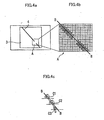
- FIGS. 4a-4c schematically represent such situations.
- FIG. 4a schematically shows the entire of a detected image, which includes a measurement object image 3 and a bright portion image 4.
- the bright portion image 4 extends linearly as a whole.
- a disturbance occurs in a region shown by reference symbol A.
- FIG. 4b shows in a large scale the region A including the disturbance.
- each square represents one pixel
- two-stage gray scale schematically shows whether or not the detected luminance for each individual pixel exceeds the threshold that is used for the determination of the bright portion pixel (refer to the graph shown in FIG. 3 and relevant explanations).
- the direction of scanning for image pickup in the image receiving device is in the left-right direction.
- the line denoted by symbol B-B represents a detected position line observed if an image of the incident position of the slit light projected onto the measurement object 1 were correctly detected.
- a group of pixels whose luminances exceed the threshold are linearly distributed with a certain width, in which no disturbance is found.
- the number of pixels having luminances exceeding the threshold is counted in the direction (here the left-right direction) of scanning in the image receiving device, the number of pixels counted for the part including a disturbance is considerably smaller than that counted for part not including a disturbance. If the detected position is calculated from a weighted average of luminances of a few pixels, the reliability of the result of calculation is poor, so that there is a possibility that the detected position is largely deviated from the correct detected position line B-B.
- FIG. 4c schematically shows such situation.
- symbols C1 and C2 each represent an example of the detected position calculated on the basis of luminances of detected pixels (which satisfy the threshold condition) that are collected along a scanning line passing through the part not including a disturbance.
- Symbol C3 represents an example of the detected position calculated based on luminances of a few pixels.
- an allowable range of the number of detected pixels in the detected image per one scanning line is determined on the basis of those numbers of the detected pixels (which satisfy the threshold condition (ditto in the following)) which are individually counted for a plurality of scanning lines. If the number of detected pixels on a given scanning line falls within the allowable range, it is determined that the detected pixels on this scanning line are proper data that can be used for the measurement of three-dimensional position information of the measurement object.
- the detected positions C1, C2 are adopted as proper data, whereas the detected position C3 is not adopted as proper data, so that irreliable data is not reflected in the results of three-dimensional measurement, making it possible to avoid the measurement accuracy being lowered.
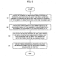
- FIG. 5 An example of concrete processing procedures including the aforementioned determination on the presence or absence of proper data is shown by a flowchart in FIG. 5. This processing is performed in the image processing unit 30 that is provided with a memory in which the required program data, parameter data, etc. are stored in advance. The main point of each step is as follows:
- the upper limit Nmax and the lower limit Nmin may be calculated in accordance with the following equations (3) and (4):
- ⁇ and ⁇ are a subtract number of pixels and an add number of pixels that are set beforehand as parameters in such a manner that the relations 0 ⁇ ⁇ and 0 ⁇ ⁇ are satisfied.
- the proper number of detected pixels varies in a range from 42 to 59.
- the preset values ⁇ min, ⁇ max; or ⁇ ; ⁇ can appropriately be altered.
- Step S3 among all the scanning lines relating to the calculation of Nav, for those scanning lines for each of which pixels whose number falls within the allowable range from Nmin to Nmax has been detected, luminance data detected for the pixels on each scanning line is determined as being proper data that is to be used for the measurement of three-dimensional position information of the measurement object 1. Then, for each scanning line for which the proper data has been obtained, the well-known weighted mean processing is performed by using weights that are respectively proportional to the detected luminances of the pixels on the scanning line, whereby the detected position (center position) of the slit light is determined.
- Step S4 on the basis of the data of detected position of the slit light that is determined at Step S3, the calculation is performed to acquire three-dimensional position information of the measurement object 1, and the calculation result is stored.
- the three-dimensional position-related information of the measurement object 1 can for example be the position of a characteristic point representative of the measurement object 1, the orientation of a surface and/or the extending direction of a ridge line which represent the orientation of the measurement object 1, the shape of a profile, the size of the profile, and the like. Which of these parameters is to be calculated from the detection data obtained at Step S3 depends on application. A method of the calculation is well known and does not directly relate to features of this invention, and therefore, details of the method will be omitted.
- the aforementioned processing is performed by the image processing unit 30.
- a robot controller may serve as the image processing unit 30 in a well known manner.
- the scanning lines (parallel to the Hz axis in FIG. 2) used for image pickup in the photodetector 20 are adopted as the "scanning lines" to be used to count the detected pixels (that satisfy the threshold condition) corresponding to the bright portion.
- lines may be used that are different in their extending direction from the scanning lines used for the image pickup in the photodetector 20, as long as these lines are not in parallel to the linear bright portion image 4.
Landscapes
- Physics & Mathematics (AREA)
- Engineering & Computer Science (AREA)
- Computer Vision & Pattern Recognition (AREA)
- General Physics & Mathematics (AREA)
- Optics & Photonics (AREA)
- Theoretical Computer Science (AREA)
- Length Measuring Devices By Optical Means (AREA)
- Image Processing (AREA)
- Image Analysis (AREA)
Claims (6)
- Dreidimensionale Messapparatur zum Erhalten von Information über eine dreidimensionale Position eines Objekts (1) auf Basis der Ermittlung einer Position von einem hellen Anteil (2), der im Wesentlichen linear erzeugt wird durch Beleuchten mit Lichtschnitt oder Pseudo-Lichtschnitt, erzeugt durch Abtasten des Objekts (1) mit Spotlicht, auf einem durch Bildaufnahmevorrichtungen (20) aufgenommenen Bild des Objekts, wobei die dreidimensionale Messapparatur folgendes umfasst:eine Einrichtung zum Zählen der Anzahl aufgehellter Pixel, die zum hellen Anteil (4) entlang jeder von einer Mehrzahl Ermittlungslinien gehören, die den hellen Anteil in dem aufgenommenen Bild durchqueren;eine Einrichtung zum Bestimmen eines zulässigen Bereichs für die Anzahl aufgehellter Pixel entlang einer Ermittlungslinie auf Basis der Anzahl aufgehellter Pixel, die jeweils entlang der Mehrzahl Ermittlungslinien gezählt werden; undeine Einrichtung zum Aufnehmen von Daten der aufgehellten Pixel entlang jeder Ermittlungslinie, wobei die Anzahl aufgehellter Pixel in dem zulässigen Bereich liegt, als richtige Daten zum Erhalten der Information in Verbindung mit der dreidimensionalen Position des Objekts.
- Dreidimensionale Messapparatur nach Anspruch 1, wobei die Information in Bezug auf die dreidimensionale Position des Objekts eine Information aus einer dreidimensionalen Position, einer dreidimensionalen Haltung, einer dreidimensionalen Gestalt und einer Größe des Objekts beinhaltet.
- Dreidimensionale Messapparatur nach Anspruch 1, wobei die Einrichtung zur Bestimmung des zulässigen Bereichs folgendes umfasst: eine Einrichtung zum Erhalten der durchschnittlichen Anzahl aufgehellter Pixel pro Ermittlungslinie auf Basis der Anzahl aufgehellter Pixel, die jeweils entlang der Mehrzahl Ermittlungslinien gezählt werden; und eine Einrichtung zum Berechnen des zulässigen Bereichs auf Basis der erhaltenen durchschnittlichen Anzahl aufgehellter Pixel und minimaler und maximaler Verhältnisse, die jeweils mit der ermittelten durchschnittlichen Anzahl aufgehellter Pixel multipliziert werden.
- Dreidimensionale Messapparatur nach Anspruch 3, wobei die minimalen und maximalen Verhältnisse veränderlich sind.
- Dreidimensionale Messapparatur nach Anspruch 1, wobei die Einrichtung zur Ermittlung des zulässigen Bereichs folgendes umfasst: eine Einrichtung zum Erhalten einer durchschnittlichen Anzahl aufgehellter Pixel pro Ermittlungslinie auf Basis der Anzahl aufgehellter Pixel, die jeweils entlang der Mehrzahl Ermittlungslinien gezählt werden; und eine Einrichtung zum Berechnen des zulässigen Bereichs auf Basis der erhaltenen durchschnittlichen Anzahl aufgehellter Pixel, einer Subtraktionszahl, die von der erhaltenen durchschnittlichen Anzahl aufgehellter Pixel subtrahiert wird, und einer Additionszahl, die zu der erhaltenen durchschnittlichen Anzahl aufgehellter Pixel addiert wird.
- Dreidimensionale Messapparatur nach Anspruch 5, wobei die Subtraktionszahl und die Additionszahl veränderlich sind.
Applications Claiming Priority (2)
| Application Number | Priority Date | Filing Date | Title |
|---|---|---|---|
| JP2003356747 | 2003-10-16 | ||
| JP2003356747A JP3892838B2 (ja) | 2003-10-16 | 2003-10-16 | 3次元測定装置 |
Publications (2)
| Publication Number | Publication Date |
|---|---|
| EP1524492A1 EP1524492A1 (de) | 2005-04-20 |
| EP1524492B1 true EP1524492B1 (de) | 2006-07-12 |
Family
ID=34373611
Family Applications (1)
| Application Number | Title | Priority Date | Filing Date |
|---|---|---|---|
| EP04256285A Expired - Fee Related EP1524492B1 (de) | 2003-10-16 | 2004-10-12 | Apparat für dreidimensionale Messungen |
Country Status (4)
| Country | Link |
|---|---|
| US (1) | US7486816B2 (de) |
| EP (1) | EP1524492B1 (de) |
| JP (1) | JP3892838B2 (de) |
| DE (1) | DE602004001500T2 (de) |
Cited By (2)
| Publication number | Priority date | Publication date | Assignee | Title |
|---|---|---|---|---|
| DE102006059416B4 (de) * | 2006-12-15 | 2009-05-20 | Fraunhofer-Gesellschaft zur Förderung der angewandten Forschung e.V. | Vorrichtung und Verfahren zur Steigerung der Messgenauigkeit digitaler 3D-Geometriemesssysteme |
| DE102009034244A1 (de) | 2009-07-22 | 2011-01-27 | Kuka Roboter Gmbh | Verfahren und Vorrichtung zur Vermessung eines Bauteils |
Families Citing this family (21)
| Publication number | Priority date | Publication date | Assignee | Title |
|---|---|---|---|---|
| JP3930482B2 (ja) * | 2004-01-19 | 2007-06-13 | ファナック株式会社 | 3次元視覚センサ |
| US20050286767A1 (en) * | 2004-06-23 | 2005-12-29 | Hager Gregory D | System and method for 3D object recognition using range and intensity |
| WO2006138525A2 (en) | 2005-06-16 | 2006-12-28 | Strider Labs | System and method for recognition in 2d images using 3d class models |
| DE102005045748A1 (de) * | 2005-09-23 | 2007-04-05 | Kappner, Helmut A. | Messvorrichtung zum Vermessen eines Werkstücks |
| US7595483B1 (en) * | 2008-06-12 | 2009-09-29 | The United States Of America As Represented By The Secretary Of The Navy | Calibration method for a stellar sensor |
| JP5310130B2 (ja) * | 2009-03-11 | 2013-10-09 | オムロン株式会社 | 3次元視覚センサによる認識結果の表示方法および3次元視覚センサ |
| JP5245938B2 (ja) * | 2009-03-12 | 2013-07-24 | オムロン株式会社 | 3次元認識結果の表示方法および3次元視覚センサ |
| JP5714232B2 (ja) * | 2009-03-12 | 2015-05-07 | オムロン株式会社 | キャリブレーション装置および3次元計測のためのパラメータの精度の確認支援方法 |
| JP5316118B2 (ja) * | 2009-03-12 | 2013-10-16 | オムロン株式会社 | 3次元視覚センサ |
| JP2010210585A (ja) * | 2009-03-12 | 2010-09-24 | Omron Corp | 3次元視覚センサにおけるモデル表示方法および3次元視覚センサ |
| JP5282614B2 (ja) * | 2009-03-13 | 2013-09-04 | オムロン株式会社 | 視覚認識処理用のモデルデータの登録方法および視覚センサ |
| JP5602392B2 (ja) * | 2009-06-25 | 2014-10-08 | キヤノン株式会社 | 情報処理装置、情報処理方法およびプログラム |
| JP5636691B2 (ja) * | 2010-02-26 | 2014-12-10 | 富士ゼロックス株式会社 | 画像処理装置及び画像処理プログラム |
| JP5170154B2 (ja) * | 2010-04-26 | 2013-03-27 | オムロン株式会社 | 形状計測装置およびキャリブレーション方法 |
| US9041769B2 (en) * | 2010-10-18 | 2015-05-26 | Will Bauer | System and method for controlling media projectors |
| JP5798318B2 (ja) * | 2010-12-15 | 2015-10-21 | キヤノン株式会社 | 距離データ生成装置、位置姿勢計測装置、距離データ生成装置の制御方法およびプログラム |
| JP6092530B2 (ja) * | 2012-06-18 | 2017-03-08 | キヤノン株式会社 | 画像処理装置、画像処理方法 |
| JP6570592B2 (ja) * | 2017-09-29 | 2019-09-04 | 株式会社牧野フライス製作所 | 工作機械の機上測定方法および制御装置 |
| JP6631647B2 (ja) * | 2018-03-08 | 2020-01-15 | 株式会社島津製作所 | 走査型プローブ顕微鏡及び表面画像補正方法 |
| DE102019123232A1 (de) * | 2019-08-29 | 2021-03-04 | SmartRay GmbH | Mehrfach-Belichtungsverfahren |
| CN112361977B (zh) * | 2020-11-10 | 2021-05-28 | 成都新西旺自动化科技有限公司 | 一种基于权重分配的直线间距测量方法 |
Family Cites Families (19)
| Publication number | Priority date | Publication date | Assignee | Title |
|---|---|---|---|---|
| JPS598086A (ja) * | 1982-07-07 | 1984-01-17 | Hitachi Ltd | 直方体状部品の平面形状検出装置 |
| JPS61191905A (ja) | 1985-02-20 | 1986-08-26 | Sumitomo Metal Ind Ltd | 開先位置検出装置 |
| JPH0810130B2 (ja) * | 1986-11-25 | 1996-01-31 | 株式会社日立製作所 | 光切断線法による物体測定装置 |
| JP3013254B2 (ja) * | 1990-06-06 | 2000-02-28 | 光洋精工株式会社 | 形状測定方法 |
| JPH04117578A (ja) | 1990-06-13 | 1992-04-17 | Yaskawa Electric Corp | ライン検出方法 |
| US6407817B1 (en) * | 1993-12-20 | 2002-06-18 | Minolta Co., Ltd. | Measuring system with improved method of reading image data of an object |
| JP2989744B2 (ja) * | 1994-06-13 | 1999-12-13 | 株式会社東芝 | 測定面抽出装置及びその方法 |
| US5852672A (en) * | 1995-07-10 | 1998-12-22 | The Regents Of The University Of California | Image system for three dimensional, 360 DEGREE, time sequence surface mapping of moving objects |
| PT822389E (pt) * | 1996-07-29 | 2003-08-29 | Elpatronic Ag | Processo e dispositivo para determinacao e verificacao do contorno de um rebordo |
| JPH10190972A (ja) * | 1996-10-25 | 1998-07-21 | Minolta Co Ltd | 画像読取り装置 |
| JP3201297B2 (ja) | 1996-12-26 | 2001-08-20 | 日本鋼管株式会社 | コイル位置検出装置 |
| US6084980A (en) * | 1997-05-13 | 2000-07-04 | 3D Systems, Inc. | Method of and apparatus for deriving data intermediate to cross-sectional data descriptive of a three-dimensional object |
| US6233049B1 (en) * | 1998-03-25 | 2001-05-15 | Minolta Co., Ltd. | Three-dimensional measurement apparatus |
| US6965689B2 (en) * | 2001-04-05 | 2005-11-15 | Thomas Eliott Lee | Image based volumetric measuring device |
| US7338168B2 (en) * | 2001-07-06 | 2008-03-04 | Palantyr Research, Llc | Particle analyzing system and methodology |
| US7024027B1 (en) * | 2001-11-13 | 2006-04-04 | Koninklijke Philips Electronics N.V. | Method and apparatus for three-dimensional filtering of angiographic volume data |
| CA2525977C (en) * | 2003-05-30 | 2012-06-26 | Karl Johann Schmidt | Rendering of soft shadows using depth maps |
| JP4756819B2 (ja) * | 2003-10-21 | 2011-08-24 | オリンパス株式会社 | 走査型顕微鏡システム |
| US7170592B2 (en) * | 2004-03-10 | 2007-01-30 | Acushnet Company | Method of inspecting a sphere without orienting the sphere |
-
2003
- 2003-10-16 JP JP2003356747A patent/JP3892838B2/ja not_active Expired - Fee Related
-
2004
- 2004-10-12 DE DE602004001500T patent/DE602004001500T2/de active Active
- 2004-10-12 EP EP04256285A patent/EP1524492B1/de not_active Expired - Fee Related
- 2004-10-13 US US10/962,542 patent/US7486816B2/en not_active Expired - Fee Related
Cited By (3)
| Publication number | Priority date | Publication date | Assignee | Title |
|---|---|---|---|---|
| DE102006059416B4 (de) * | 2006-12-15 | 2009-05-20 | Fraunhofer-Gesellschaft zur Förderung der angewandten Forschung e.V. | Vorrichtung und Verfahren zur Steigerung der Messgenauigkeit digitaler 3D-Geometriemesssysteme |
| DE102009034244A1 (de) | 2009-07-22 | 2011-01-27 | Kuka Roboter Gmbh | Verfahren und Vorrichtung zur Vermessung eines Bauteils |
| EP2281666A1 (de) | 2009-07-22 | 2011-02-09 | KUKA Roboter GmbH | Simulationsverfahren und -vorrichtung zur Vermessung eines Bauteils und Optimierung der realen entsprechenden Vermessung |
Also Published As
| Publication number | Publication date |
|---|---|
| DE602004001500T2 (de) | 2006-11-16 |
| JP3892838B2 (ja) | 2007-03-14 |
| DE602004001500D1 (de) | 2006-08-24 |
| JP2005121486A (ja) | 2005-05-12 |
| US20050084149A1 (en) | 2005-04-21 |
| EP1524492A1 (de) | 2005-04-20 |
| US7486816B2 (en) | 2009-02-03 |
Similar Documents
| Publication | Publication Date | Title |
|---|---|---|
| EP1524492B1 (de) | Apparat für dreidimensionale Messungen | |
| US11308343B2 (en) | Method and device for automatically identifying a point of interest in a depth measurement on a viewed object | |
| US8233041B2 (en) | Image processing device and image processing method for performing three dimensional measurements | |
| US8970853B2 (en) | Three-dimensional measurement apparatus, three-dimensional measurement method, and storage medium | |
| US7202957B2 (en) | Three-dimensional visual sensor | |
| US11170516B2 (en) | Method and device for measuring features on or near an object | |
| US9488469B1 (en) | System and method for high-accuracy measurement of object surface displacement using a laser displacement sensor | |
| KR100499764B1 (ko) | 디지털 이미지에서 객체를 측정하는 방법 및 시스템 | |
| CN109255844B (zh) | 用于使用视频检查设备测量特征的尺寸的方法 | |
| JP6865046B2 (ja) | 視認物体の深度測定において関心点を自動的に識別する方法および装置 | |
| CN108027233B (zh) | 用于测量物体上或附近的特征的方法及装置 | |
| WO2017003650A1 (en) | Method and system for detecting known measurable object features | |
| EP3839418A1 (de) | Optischer sensor mit übersichtskamera | |
| US10432916B2 (en) | Measurement apparatus and operation method of measurement apparatus | |
| WO2019230284A1 (ja) | 三次元計測装置、三次元計測装置の位置表示方法およびプログラム | |
| JP3888528B2 (ja) | 液面認識処理装置及び液面監視システム | |
| JP5339070B2 (ja) | 変位量測定装置及び同測定方法 | |
| JP5621077B2 (ja) | 三次元計測装置及び三次元計測方法 | |
| JP2006349443A (ja) | カメラ校正装置 | |
| JPH08110206A (ja) | 位置及び姿勢検出方法と位置及び姿勢検出装置 | |
| CN113641318B (zh) | 显示数据校准方法及系统 | |
| JP6022331B2 (ja) | カメラシステム | |
| CN116071507A (zh) | 信息处理装置、信息处理系统、信息处理方法和记录介质 |
Legal Events
| Date | Code | Title | Description |
|---|---|---|---|
| PUAI | Public reference made under article 153(3) epc to a published international application that has entered the european phase |
Free format text: ORIGINAL CODE: 0009012 |
|
| AK | Designated contracting states |
Kind code of ref document: A1 Designated state(s): AT BE BG CH CY CZ DE DK EE ES FI FR GB GR HU IE IT LI LU MC NL PL PT RO SE SI SK TR |
|
| AX | Request for extension of the european patent |
Extension state: AL HR LT LV MK |
|
| 17P | Request for examination filed |
Effective date: 20050609 |
|
| AKX | Designation fees paid |
Designated state(s): DE |
|
| GRAP | Despatch of communication of intention to grant a patent |
Free format text: ORIGINAL CODE: EPIDOSNIGR1 |
|
| GRAS | Grant fee paid |
Free format text: ORIGINAL CODE: EPIDOSNIGR3 |
|
| GRAA | (expected) grant |
Free format text: ORIGINAL CODE: 0009210 |
|
| AK | Designated contracting states |
Kind code of ref document: B1 Designated state(s): DE |
|
| REF | Corresponds to: |
Ref document number: 602004001500 Country of ref document: DE Date of ref document: 20060824 Kind code of ref document: P |
|
| PLBE | No opposition filed within time limit |
Free format text: ORIGINAL CODE: 0009261 |
|
| STAA | Information on the status of an ep patent application or granted ep patent |
Free format text: STATUS: NO OPPOSITION FILED WITHIN TIME LIMIT |
|
| 26N | No opposition filed |
Effective date: 20070413 |
|
| PGFP | Annual fee paid to national office [announced via postgrant information from national office to epo] |
Ref country code: DE Payment date: 20091123 Year of fee payment: 6 |
|
| REG | Reference to a national code |
Ref country code: DE Ref legal event code: R119 Ref document number: 602004001500 Country of ref document: DE Effective date: 20110502 |
|
| PG25 | Lapsed in a contracting state [announced via postgrant information from national office to epo] |
Ref country code: DE Free format text: LAPSE BECAUSE OF NON-PAYMENT OF DUE FEES Effective date: 20110502 |