EP1524399A1 - Security barrier - Google Patents
Security barrier Download PDFInfo
- Publication number
- EP1524399A1 EP1524399A1 EP04292469A EP04292469A EP1524399A1 EP 1524399 A1 EP1524399 A1 EP 1524399A1 EP 04292469 A EP04292469 A EP 04292469A EP 04292469 A EP04292469 A EP 04292469A EP 1524399 A1 EP1524399 A1 EP 1524399A1
- Authority
- EP
- European Patent Office
- Prior art keywords
- gate
- door
- opening
- upright
- intended
- Prior art date
- Legal status (The legal status is an assumption and is not a legal conclusion. Google has not performed a legal analysis and makes no representation as to the accuracy of the status listed.)
- Granted
Links
Images


Classifications
-
- E—FIXED CONSTRUCTIONS
- E06—DOORS, WINDOWS, SHUTTERS, OR ROLLER BLINDS IN GENERAL; LADDERS
- E06B—FIXED OR MOVABLE CLOSURES FOR OPENINGS IN BUILDINGS, VEHICLES, FENCES OR LIKE ENCLOSURES IN GENERAL, e.g. DOORS, WINDOWS, BLINDS, GATES
- E06B9/00—Screening or protective devices for wall or similar openings, with or without operating or securing mechanisms; Closures of similar construction
- E06B9/02—Shutters, movable grilles, or other safety closing devices, e.g. against burglary
-
- E—FIXED CONSTRUCTIONS
- E06—DOORS, WINDOWS, SHUTTERS, OR ROLLER BLINDS IN GENERAL; LADDERS
- E06B—FIXED OR MOVABLE CLOSURES FOR OPENINGS IN BUILDINGS, VEHICLES, FENCES OR LIKE ENCLOSURES IN GENERAL, e.g. DOORS, WINDOWS, BLINDS, GATES
- E06B9/00—Screening or protective devices for wall or similar openings, with or without operating or securing mechanisms; Closures of similar construction
- E06B2009/002—Safety guards or gates
Definitions
- the invention relates to a safety gate, of the type comprising two side amounts of which at least one is intended to be associated with the amount an opening made in a fixed wall.
- the invention relates to a safety gate intended for prevent young children from entering an area likely to be dangerous, such as a staircase.
- safety barriers are known. arranged to be placed in front of an area likely to be dangerous, these barriers must be raised and moved in their entirety when user wants to enter this area.
- the gate according to the invention can also be used well in a mode called “barrier simple” that in a mode called “barrier "gate”, according to the wishes of the user, thanks to its modular structure.
- the means for fixing and locking this gate make particularly simple its installation in one of the two modes mentioned above, as well as its use once installed.
- the fixing means comprise two pivoting elements arranged respectively in the vicinity of each end of the door jamb, each pivoting member comprising a movable part fixed to the amount of the gate, and a fixed part forming receptacle of the mobile part, said fixed part being intended to be associated to the amount of the opening.
- the means for fixing the gate comprise two buffer elements arranged respectively at near each end of the door jamb, each element forming buffer being intended, when the gate passes to the blocking position, to come resting on a cup attached to the amount of the opening.
- the safety gate 1 shown in the drawings comprises two amounts 2a, 2b of which at least one 2a is intended to be fixed to the amount 3 of a opening made in a fixed wall.
- the fixed wall can be a wall, the frame of a door, the amount of a staircase.
- the gate 1 comprises a rectangular central panel 4 delimited by minus two horizontal bars 5a, 5b and two vertical bars 6a, 6b.
- this central panel 4 is formed of a plurality of vertical bars to prevent the passage from one side to the other of the gate 1 when the latter, once mounted, is in the closed position.
- the gate 1 also comprises locking means in the position of blocking, this position being intended to prevent the passage of, for example, young children to a potentially dangerous area.
- the locking means comprise two deformable parallelograms formed between the central panel 4 and each of the lateral uprights 2a, 2b of the In particular, according to the two embodiments shown respectively in FIGS. 1 and 3, these locking means comprise four displaceable elements forming a square 7 respectively arranged between the end 8 of a horizontal bar 5a, 5b of the central panel 4 and the end 9 a lateral amount 2a, 2b of the gate, each element forming square 7 being arranged to allow deformation of the parallelograms when the gate 1 pass, by manual action, from a locking position to a position of release.
- Each element 7 is formed of two parts 10, 11 substantially triangular designed to fit into one another when mounting the gate 1.
- the female part 10 comprises two organs cylindrical projections 12 each located at one of the vertices 13 of the triangle, and arranged on the one hand to receive screws fixing the gate, by the side outside 14, and secondly to receive the projecting members 15 of form complementary to the male part 11.
- a hollow wall 16 protruding towards the inside of the female part 10 is arranged to receive a complementary wall 17 of the male part 11.
- This structure makes it possible to fix reliably the male part 11 of the element to the female part 10, and by therefore, to mount the lateral uprights 2a, 2b of the door 1 to both horizontal bars upper and lower 5a, 5b, a member 7 forming bracket being provided to form each corner of the door 1.
- the safety gate 1 also comprises fastening means of the minus one of the wicket amounts to one of the opening amounts, these fixing means being removable, so as to authorize the use of the same gate in both "gate barrier” and “barrier” modes simple.
- the fastening means comprise two pivoting elements 18 situated respectively in the vicinity of each end 9 of the lateral amount 2a of the gate.
- each pivoting element 18 comprises a movable part fixed to the amount 2a of the gate, and a fixed part forming part of the movable part, said fixed part being intended to be associated with the amount 3 of the opening.
- the moving part is formed of a hollow cylinder 19.
- the geometry internal cylinder 19 is adapted to partially receive a threaded screw 20 hexagonal adjustment, and the external geometry of cylinder 19 is arranged to allow the screw-cylinder assembly to pivot within the receptacle.
- the screw 20 is provided to allow adjustment in width of the gate 1, so as to be able to optimally adapt said gate to dimensions of the opening.
- the fixed part, or receptacle comprises a hollow shell 21, the hollow part 22 being of cylindrical shape so as to be able to receive, by its rear face 23, the cylinder 19 provided with the adjustment screw 20.
- the front face 24 is pierced with to leave a passage for the adjusting screw 20, the opening being provided to allow rotation of the cylinder-screw assembly by about 180 degrees.
- the front face 24 further comprises a protruding lip 25 whose function is, when mounting and adjustment of gate 1, to maintain a minimum distance between the lateral amount 2a of the door and the upper part of the hull 21.
- the receptacle also comprises, at the top and bottom, orifices 26 allowing insertion of mounting screws for attachment to the amount 3 of the opening.
- the rear face 23 of the shell 21 comprises ribs on which a rectangular plate 27 is intended to be positioned.
- This plate 27 comprises a concave inner surface 28 for receiving the movable cylinder 19, and a flat outer surface 29 to be applied to the fixed wall.
- the plate 27 also comprises upper and lower tabs 30, allowing to position it accurately during its assembly but also to prevent him from entering the hull 21, which would hinder the rotation of the cylinder 19.
- This plate 27 has the function of absorbing the force exerted on cylinder-screw adjustment, when the gate is in the position of blocking.
- Figure 2b shows such a fastening means once assembled.
- the head of the adjusting screw 20 is first inserted into the hollow part of the movable cylinder 19, then the cylinder-screw assembly is placed in the inside of the shell 21, and the rear plate 27 is then arranged.
- the end 31 of the screw 20 opposite its head can then be inserted into a orifice 32 of suitable size and geometry, located in the lateral amount 2a of the gate 1, this insertion can be carried out before or after the fixing of the receptacle on the fixed wall.
- the fastening means comprise two buffer members 33 arranged respectively in the vicinity of each end 9 of the lateral amount of gate.
- Each buffer element 9 consists of a threaded screw of adjustment 34 whose head is formed by an elastomeric pad 35.
- the screw 34 is intended to be inserted into an orifice 32 of suitable size and geometry, located in the lateral amount 2a of the door, the head 35 of the screw and come to bear against the fixed wall.
- the screw 34 is intended to allow the adjustment in width of the gate 1, so as to be able to adapt optimally said gate to the dimensions of the opening.
- each buffer element 33 is intended, when the gate 1 goes into the blocking position, to bear on a cup 36 fixed to the amount 3 of the opening.
- This cup 36 includes a hollow internal portion 37 of a size adapted to receive the screw head, a outer surface 38 substantially flat to bear against the wall fixed, and a central orifice 39 arranged to receive a fixing screw to the wall, without disturbing the positioning of the elastomeric buffer 35.
- the safety gate 1 may comprise means for fixing the second amount 2b of gate 1 to the corresponding amount 3 of the opening, said fixing means comprising buffer elements 33 disposed respectively in the vicinity of each end 9 of the second 2b amount of the gate.
- these fixing means have a structure identical to that of the fixing means described in relation to the Figures 3 and 4.
- the safety gate shown is formed by two half-frames 40 superimposed, each half-frame 40 being provided with fixing means to the other half-frame, said fixing means being arranged to allow the adjustment in width of the gate 1 so as to adapt it optimally to the dimensions of the opening.
- these fastening means include orifices 41 arranged to receive fastening screws.
- the amounts and the bars forming the gate 1 are made of wood, and the means of fixing and locking are in plastic, with the exception of steel adjustment screws.
- the door of Safety 1 can be used either in “gate barrier” mode ( Figures 1 and 2) or in “simple barrier” mode ( Figures 3 and 4), the removable nature of these securing means allowing the user to easily switch from one mode to another from one user to another, according to his needs.
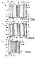
- FIGS. 1a, 1b and 1c show the gate 1 of which one of the amounts is fixed to the amount 3 of the opening according to the "gate barrier" mode.
- the second lateral amount 2b of the door comprises fixing means in form buffer elements 33.
- the elements forming buffer 33 are supported on the cups 36, and the elements forming square 7 are arranged in such a way that a parallelogram is formed between the lateral uprights 2a, 2b, the extreme vertical bars 6a, 6b and the bars horizontal 5a, 5b.
- the passage of the gate 1 in the locking position is, conversely, by support user manual on the top horizontal bar 5a, the door having been previously pivotally placed in the closed position, that is to say in a position in which the buffer elements 33 of the second amount 2b are located next to the cups 36.
- the unlocking position is effected by manual lifting of the upper horizontal bar 5a, which causes the deformation of the parallelogram by rotation of the square elements 7 (see FIGS. 3d).
- the gate 1 can then be moved in the completely raising, the buffer elements 33 amounts side 2a, 2b being taken out of the cups 36.
- the transition to the position of blocking is done as before by pressing on the horizontal bar upper 5a, the gate 1 having been previously placed in the closed position, i.e. in a position in which the buffer elements 33 two lateral uprights 2a, 2b are located opposite the cups 36 corresponding.
Abstract
Description
L'invention concerne un portillon de sécurité, du type comprenant deux montants latéraux dont au moins l'un est destiné à être associé au montant d'une ouverture réalisée dans une paroi fixe.The invention relates to a safety gate, of the type comprising two side amounts of which at least one is intended to be associated with the amount an opening made in a fixed wall.
Plus particulièrement, l'invention concerne un portillon de sécurité destiné à empêcher les jeunes enfants d'entrer dans une zone susceptible d'être dangereuse, telle qu'un escalier.More particularly, the invention relates to a safety gate intended for prevent young children from entering an area likely to be dangerous, such as a staircase.
On connaít déjà des portillons dont la fonction est de limiter ou de sécuriser le passage vers une zone déterminée, ces portillons comprenant généralement un montant latéral destiné à être fixé sur une surface stable, et un battant pivotant. Ces portillons présentent l'avantage d'être facilement manoeuvrables en ce qui concerne leur ouverture ou fermeture.We already know gates whose function is to limit or secure the passage to a given zone, these gates generally comprising a side upright intended to be fixed on a stable surface, and a pivoting flap. These gates have the advantage of being easily maneuverable with regard to concerns their opening or closing.
Par ailleurs, pour l'application considérée, on connaít des barrières de sécurité agencées pour être posées devant une zone susceptible d'être dangereuse, ces barrières devant être soulevées et déplacées dans leur totalité lorsqu'un utilisateur désire pénétrer dans cette zone.Moreover, for the application in question, safety barriers are known. arranged to be placed in front of an area likely to be dangerous, these barriers must be raised and moved in their entirety when user wants to enter this area.
La demanderesse a mis au point un portillon de sécurité permettant de bloquer provisoirement l'accès à une zone potentiellement dangereuse, ce dispositif combinant les avantages procurés à la fois par un portillon et par une barrière simple de sécurité. En effet, le portillon selon l'invention peut être utilisé aussi bien dans un mode dit « barrière simple » que dans un mode dit « barrière portillon », selon le souhait de l'utilisateur, et ce grâce à sa structure modulable.The applicant has developed a safety gate to block provisionally access to a potentially hazardous area, this combining the benefits of both a gate and a barrier simple security. Indeed, the gate according to the invention can also be used well in a mode called "barrier simple" that in a mode called "barrier "gate", according to the wishes of the user, thanks to its modular structure.
En outre, les moyens de fixation et de verrouillage de ce portillon rendent particulièrement simples son installation dans l'un des deux modes mentionnés ci-dessus, ainsi que son utilisation une fois installé. In addition, the means for fixing and locking this gate make particularly simple its installation in one of the two modes mentioned above, as well as its use once installed.
A cet effet, l'invention a pour objet un portillon de sécurité du type comprenant deux montants latéraux dont au moins l'un est destiné à être fixé au montant d'une ouverture réalisée dans une paroi fixe, ledit portillon comprenant :
- un panneau central délimité par au moins deux barres horizontales et deux barres verticales ;
- des moyens de verrouillage en position de blocage ;
- des moyens de fixation d'au moins l'un des montants du portillon à l'un des montants de l'ouverture ;
- a central panel delimited by at least two horizontal bars and two vertical bars;
- locking means in the locking position;
- means for fixing at least one of the door jambs to one of the amounts of the opening;
Selon un premier mode de réalisation, les moyens de fixation comprennent deux éléments de pivotement disposés respectivement au voisinage de chaque extrémité du montant du portillon, chaque élément de pivotement comprenant une partie mobile fixée au montant du portillon, et une partie fixe formant réceptacle de la partie mobile, ladite partie fixe étant destinée à être associée au montant de l'ouverture.According to a first embodiment, the fixing means comprise two pivoting elements arranged respectively in the vicinity of each end of the door jamb, each pivoting member comprising a movable part fixed to the amount of the gate, and a fixed part forming receptacle of the mobile part, said fixed part being intended to be associated to the amount of the opening.
Cette réalisation correspond à l'utilisation du portillon en mode « barrière portillon », qui permet de l'ouvrir et le fermer par rotation.This achievement corresponds to the use of the gate in "barrier mode" "gate", which allows to open and close it by rotation.
Selon un deuxième mode de réalisation, les moyens de fixation du portillon comprennent deux éléments formant tampon disposés respectivement au voisinage de chaque extrémité du montant du portillon, chaque élément formant tampon étant destiné, lorsque le portillon passe en position de blocage, à venir en appui sur une coupelle fixée au montant de l'ouverture.According to a second embodiment, the means for fixing the gate comprise two buffer elements arranged respectively at near each end of the door jamb, each element forming buffer being intended, when the gate passes to the blocking position, to come resting on a cup attached to the amount of the opening.
Cette réalisation correspond à l'utilisation du portillon en mode « barrière simple », qui permet de déplacer entièrement le portillon sans avoir besoin de monter ou démonter ses moyens de fixation, lorsque l'utilisateur souhaite respectivement le mettre en place ou bien le ranger. This achievement corresponds to the use of the gate in "barrier mode" "simple", which allows the gate to be moved completely without the need for mount or dismount its fastening means, when the user wishes respectively put it in place or put it away.
On décrira maintenant à titre d'exemple non limitatif deux modes de réalisation particuliers de l'invention en référence aux dessins schématiques annexés dans lesquels :
- les figures 1 a, 1 b et 1 c sont des vues de face du portillon selon l'invention, montrant les montants de l'ouverture sur laquelle est placé le portillon, et selon un premier mode de réalisation des moyens de fixation, le portillon étant respectivement dans sa position de blocage (figure 1a), de déblocage (figure 1 b), et en position ouverte (figure 1 c) ;
- les figures 2a et 2b sont des vues en perspective des éléments formant les moyens de fixation du portillon selon le premier mode de réalisation, avant et après leur assemblage ;
- les figures 3a, 3b, 3c et 3d sont des vues de face du portillon selon l'invention, selon un deuxième mode de réalisation des moyens de fixation, les figures 3c et 3d montrant de façon agrandie les moyens de verrouillage, le portillon étant respectivement dans sa position de blocage (figures 3a et 3c) et dans sa position de déblocage (figures 3b et 3d) ;
- la figure 4 est une vue éclatée du portillon de la figure 3, montrant en outre, de façon agrandie et en perspective, une coupelle destinée à être fixée au montant de l'ouverture et à recevoir les moyens de fixation du portillon, ainsi qu'un élément formant équerre destiné au verrouillage du portillon en position de blocage.
- FIGS. 1a, 1b and 1c are front views of the gate according to the invention, showing the amounts of the opening on which the gate is placed, and according to a first embodiment of the fixing means, the gate being respectively in its blocking position (Figure 1a), unblocking (Figure 1b), and in the open position (Figure 1c);
- Figures 2a and 2b are perspective views of the elements forming the gate of the fastening means according to the first embodiment, before and after their assembly;
- FIGS. 3a, 3b, 3c and 3d are front views of the gate according to the invention, according to a second embodiment of the fixing means, FIGS. 3c and 3d showing in an enlarged manner the locking means, the gate being respectively in its blocking position (Figures 3a and 3c) and in its unlocking position (Figures 3b and 3d);
- FIG. 4 is an exploded view of the gate of FIG. 3, further showing, in an enlarged manner and in perspective, a cup intended to be fixed to the amount of the opening and to receive the means for fixing the gate, as well as a bracket member for locking the gate in the locking position.
Le portillon de sécurité 1 représenté aux dessins comprend deux montants
latéraux 2a, 2b dont au moins l'un 2a est destiné à être fixé au montant 3 d'une
ouverture réalisée dans une paroi fixe. La paroi fixe peut être un mur,
l'encadrement d'une porte, le montant d'un escalier.The
Le portillon 1 comprend un panneau central rectangulaire 4 délimité par au
moins deux barres horizontales 5a, 5b et deux barres verticales 6a, 6b. Dans
les réalisations représentées, ce panneau central 4 est formé d'une pluralité de
barres verticales destinées à empêcher le passage d'un côté à l'autre du
portillon 1 lorsque celui-ci, une fois monté, est en position fermée.The
Le portillon 1 comprend également des moyens de verrouillage en position de
blocage, cette position étant destinée à empêcher le passage par exemple de
jeunes enfants vers une zone potentiellement dangereuse.The
Les moyens de verrouillage comprennent deux parallélogrammes déformables
formés entre le panneau central 4 et chacun des montants latéraux 2a, 2b du
portillon 1. En particulier, selon les deux modes de réalisation représentés
respectivement sur les figures 1 et 3, ces moyens de verrouillage comprennent
quatre éléments déplaçables formant équerre 7 disposés respectivement entre
l'extrémité 8 d'une barre horizontale 5a, 5b du panneau central 4 et l'extrémité 9
d'un montant latéral 2a, 2b du portillon, chaque élément formant équerre 7 étant
agencé pour permettre la déformation des parallélogrammes lorsque le portillon
1 passe, par action manuelle, d'une position de blocage à une position de
déblocage.The locking means comprise two deformable parallelograms
formed between the central panel 4 and each of the
Les éléments formant équerre 7 sont représentés de façon agrandie sur les
figures 3c, 3d et sur la figure 4. Chaque élément 7 est formé de deux parties 10,
11 sensiblement triangulaires destinées à venir s'emboíter l'une dans l'autre
lors du montage du portillon 1. La partie femelle 10 comprend deux organes
saillants cylindriques 12 situés chacun à l'un des sommets 13 du triangle, et
agencés d'une part pour recevoir des vis de fixation au portillon, par le côté
extérieur 14, et d'autre part pour recevoir des organes saillants 15 de forme
complémentaire disposés sur la partie mâle 11. En outre, une paroi creuse 16
saillant vers l'intérieur de la partie femelle 10, est agencée pour recevoir une
paroi complémentaire 17 de la partie mâle 11. Cette structure permet de fixer
de façon fiable la partie mâle 11 de l'élément à la partie femelle 10, et par
conséquent de monter les montants latéraux 2a, 2b du portillon 1 aux deux
barres horizontales supérieure et inférieure 5a, 5b, un élément 7 formant
équerre étant prévu pour former chaque coin du portillon 1. The
Le portillon de sécurité 1 comprend également des moyens de fixation d'au
moins l'un des montants du portillon à l'un des montants de l'ouverture, ces
moyens de fixation étant amovibles, de sorte à autoriser l'utilisation du même
portillon aussi bien en mode « barrière portillon » qu'en mode « barrière
simple ».The
Selon un premier mode de réalisation, représenté sur les figures 1 et 2, les
moyens de fixation comprennent deux éléments de pivotement 18 situés
respectivement au voisinage de chaque extrémité 9 du montant latéral 2a du
portillon. Comme il apparaít sur la figure 2a, chaque élément de pivotement 18
comprend une partie mobile fixée au montant 2a du portillon, et une partie fixe
formant réceptacle de la partie mobile, ladite partie fixe étant destinée à être
associée au montant 3 de l'ouverture.According to a first embodiment, represented in FIGS. 1 and 2, the
fastening means comprise two pivoting
En particulier, la partie mobile est formée d'un cylindre creux 19. La géométrie
interne du cylindre 19 est adaptée pour recevoir partiellement une vis filetée 20
de réglage à tête hexagonale, et la géométrie externe du cylindre 19 est
agencée pour permettre à l'ensemble vis-cylindre de pivoter à l'intérieur du
réceptacle. La vis 20 est prévue pour permettre le réglage en largeur du
portillon 1, de sorte à pouvoir adapter de façon optimale ledit portillon aux
dimensions de l'ouverture.In particular, the moving part is formed of a
La partie fixe, ou réceptacle, comprend une coque creuse 21, la partie creuse
22 étant de forme cylindrique de sorte à pouvoir recevoir, par sa face arrière 23,
le cylindre 19 muni de la vis de réglage 20. La face avant 24 est percée de
sorte à laisser un passage pour la vis de réglage 20, l'ouverture étant prévue
pour permettre une rotation de l'ensemble cylindre-vis d'environ 180 degrés. La
face avant 24 comprend en outre une lèvre saillante 25 dont la fonction est, lors
du montage et du réglage du portillon 1, de conserver une distance minimale
entre le montant latéral 2a du portillon et la partie supérieure de la coque 21. The fixed part, or receptacle, comprises a
Le réceptacle comprend également, en partie supérieure et inférieure, des
orifices 26 permettant l'insertion de vis de montage en vue de sa fixation sur le
montant 3 de l'ouverture.The receptacle also comprises, at the top and bottom,
La face arrière 23 de la coque 21 comprend des nervures sur lesquelles une
plaque rectangulaire 27 est destinée à être positionnée. Cette plaque 27
comprend une surface interne concave 28 destinée à recevoir le cylindre mobile
19, et une surface externe plane 29 destinée à être appliquée sur la paroi fixe.
La plaque 27 comprend également des pattes 30 supérieure et inférieure,
permettant de la positionner de façon précise lors de son montage mais
également de lui éviter de pénétrer dans la coque 21, ce qui gênerait la rotation
du cylindre 19. Cette plaque 27 a pour fonction d'absorber la force exercée sur
l'ensemble cylindre-vis de réglage, lorsque le portillon est en position de
blocage.The
La figure 2b montre un tel moyen de fixation une fois assemblé. Pour cet
assemblage, la tête de la vis de réglage 20 est tout d'abord insérée dans la
partie creuse du cylindre mobile 19, puis l'ensemble cylindre-vis est placé à
l'intérieur de la coque 21, et la plaque arrière 27 est ensuite disposée.
L'extrémité 31 de la vis 20 opposée à sa tête peut alors être insérée dans un
orifice 32 de taille et de géométrie adaptées, situé dans le montant latéral 2a du
portillon 1, cette insertion pouvant être réalisée avant ou après la fixation du
réceptacle sur la paroi fixe.Figure 2b shows such a fastening means once assembled. For this
assembly, the head of the adjusting
Selon un deuxième mode de réalisation, représenté sur les figures 3 et 4, les
moyens de fixation comprennent deux éléments formant tampon 33 disposés
respectivement au voisinage de chaque extrémité 9 du montant latéral du
portillon. Chaque élément formant tampon 9 est constitué d'une vis filetée de
réglage 34 dont la tête est formée par un tampon élastomère 35. La vis 34 est
destinée à être insérée dans un orifice 32 de taille et de géométrie adaptées,
situé dans le montant latéral 2a du portillon, la tête 35 de la vis pouvant ainsi
venir en appui contre la paroi fixe. La vis 34 est prévue pour permettre le
réglage en largeur du portillon 1, de sorte à pouvoir adapter de façon optimale
ledit portillon aux dimensions de l'ouverture.According to a second embodiment, shown in FIGS. 3 and 4, the
fastening means comprise two
Dans la réalisation représentée, chaque élément formant tampon 33 est
destiné, lorsque le portillon 1 passe en position de blocage, à venir en appui sur
une coupelle 36 fixée au montant 3 de l'ouverture. Cette coupelle 36 comprend
une partie interne creuse 37 de taille adaptée à recevoir la tête 35 de vis, une
surface externe 38 sensiblement plane destinée à être en appui contre la paroi
fixe, ainsi qu'un orifice central 39 agencé pour recevoir une vis de fixation à la
paroi, et ce sans gêner le positionnement du tampon élastomère 35.In the embodiment shown, each
En outre, le portillon de sécurité 1 peut comprendre des moyens de fixation du
second montant 2b du portillon 1 au montant correspondant 3 de l'ouverture,
lesdits moyens de fixation comprenant des éléments formant tampon 33
disposés respectivement au voisinage de chaque extrémité 9 du second
montant 2b du portillon. Selon une réalisation, ces moyens de fixation ont une
structure identique à celle des moyens de fixation décrits en relation avec les
figures 3 et 4.In addition, the
Par ailleurs, le portillon de sécurité représenté est formé par deux demi-cadres
40 superposés, chaque demi-cadre 40 étant pourvu de moyens de fixation à
l'autre demi-cadre, lesdits moyens de fixation étant agencés pour permettre le
réglage en largeur du portillon 1 de sorte à l'adapter de façon optimale aux
dimensions de l'ouverture. Selon une réalisation, ces moyens de fixation
comprennent des orifices 41 agencés pour recevoir des vis de fixation.In addition, the safety gate shown is formed by two half-
Dans un exemple particulier, les montants et les barres formant le portillon 1
sont en bois, et les moyens de fixation et de verrouillage sont en matière
plastique, à l'exception des vis de réglage en acier.In a particular example, the amounts and the bars forming the
Ainsi, selon les moyens de fixation choisis par l'utilisateur, le portillon de
sécurité 1 peut être utilisé soit en mode « barrière portillon » (figures 1 et 2) soit
en mode « barrière simple » (figures 3 et 4), le caractère amovible de ces
moyens de fixation permettant à l'utilisateur de passer facilement d'un mode
d'utilisation à un autre, selon ses besoins.Thus, according to the fastening means chosen by the user, the door of
On décrit à présent le fonctionnement du portillon de sécurité 1, en relation
avec les figures 1 et 3.We now describe the operation of the
Les figures 1 a, 1b et 1 c montrent le portillon 1 dont l'un 2a des montants est
fixé au montant 3 de l'ouverture selon le mode « barrière portillon ». Le second
montant latéral 2b du portillon comprend des moyens de fixation sous forme
d'éléments formant tampon 33. En position de blocage (figure 1 a) les éléments
formant tampon 33 sont en appui sur les coupelles 36, et les éléments formant
équerre 7 sont disposés de telle sorte qu'un parallélogramme soit formé entre
les montants latéraux 2a, 2b, les barres verticales extrêmes 6a, 6b et les barres
horizontales 5a, 5b.FIGS. 1a, 1b and 1c show the
Pour faire passer le portillon 1 en position de déblocage (figure 1 b), l'utilisateur
doit soulever manuellement la barre horizontale supérieure 5a du portillon.
Cette action entraíne le pivotement des éléments formant équerre 7 autour des
axes de rotation 42 prévus sur deux de leurs sommets 13, ce qui a pour
conséquence la déformation des parallélogrammes vers le haut et une
diminution de la largeur du portillon 1. Les éléments formant tampon 33
s'éloignent des coupelles 36, et le portillon 1 est ainsi déplaçable. Comme
représenté sur la figure 1c, le portillon 1 peut alors être ouvert par pivotement
autour des moyens de fixation du premier montant latéral 2a.To move the
Le passage du portillon 1 en position de blocage se fait, à l'inverse, par appui
manuel de l'utilisateur sur la barre horizontale supérieure 5a, le portillon ayant
été préalablement placé par pivotement en position fermée, c'est-à-dire dans
une position dans laquelle les éléments formant tampon 33 du deuxième
montant 2b sont situés en regard des coupelles 36.The passage of the
De même, dans le mode de réalisation représenté sur les figures 3a et 3b, le
passage en position de déblocage s'effectue par soulèvement manuel de la
barre horizontale supérieure 5a, ce qui entraíne la déformation du
parallélogramme par rotation des éléments formant équerre 7 (voir figures 3b et
3d). Dans ce mode de réalisation, le portillon 1 peut alors être déplacé en le
soulevant complètement, les éléments formant tampon 33 des montants
latéraux 2a, 2b étant sortis des coupelles 36. Le passage en position de
blocage s'effectue comme précédemment par appui sur la barre horizontale
supérieure 5a, le portillon 1 ayant été préalablement placé en position fermée,
c'est-à-dire dans une position dans laquelle les éléments formant tampon 33
des deux montants latéraux 2a, 2b sont situés en regard des coupelles 36
correspondantes.Similarly, in the embodiment shown in FIGS. 3a and 3b, the
the unlocking position is effected by manual lifting of the
upper
Claims (7)
Applications Claiming Priority (2)
| Application Number | Priority Date | Filing Date | Title |
|---|---|---|---|
| FR0350693A FR2861125B1 (en) | 2003-10-16 | 2003-10-16 | SECURITY PORTILLON |
| FR0350693 | 2003-10-16 |
Publications (2)
| Publication Number | Publication Date |
|---|---|
| EP1524399A1 true EP1524399A1 (en) | 2005-04-20 |
| EP1524399B1 EP1524399B1 (en) | 2007-12-12 |
Family
ID=34355525
Family Applications (1)
| Application Number | Title | Priority Date | Filing Date |
|---|---|---|---|
| EP04292469A Not-in-force EP1524399B1 (en) | 2003-10-16 | 2004-10-18 | Security barrier |
Country Status (4)
| Country | Link |
|---|---|
| EP (1) | EP1524399B1 (en) |
| AT (1) | ATE380919T1 (en) |
| DE (1) | DE602004010593T2 (en) |
| FR (1) | FR2861125B1 (en) |
Cited By (5)
| Publication number | Priority date | Publication date | Assignee | Title |
|---|---|---|---|---|
| FR2925101A1 (en) * | 2007-12-13 | 2009-06-19 | Sas Michel Nordlinger Soc Par | Safety barrier for preventing infant from entering e.g. staircase, in house, has coupling units including parts that are received in housings placed in posts and crosspieces/bars, respectively, where parts are rotatably moved in housings |
| EP2696024A1 (en) * | 2012-08-08 | 2014-02-12 | Briconord | Improved safety barrier |
| FR3021989A1 (en) * | 2014-06-10 | 2015-12-11 | Briconord | CLOSURE FRAMEWORK SYSTEM |
| CN106869760A (en) * | 2017-03-23 | 2017-06-20 | 江苏固耐特围栏系统股份有限公司 | The installation method of anti-deformation bottom girder and the translation door with this bottom girder and door |
| US20230175317A1 (en) * | 2021-12-03 | 2023-06-08 | Demby Development Co., Ltd. | Safety gate |
Families Citing this family (2)
| Publication number | Priority date | Publication date | Assignee | Title |
|---|---|---|---|---|
| DE102011010540A1 (en) * | 2011-02-07 | 2012-08-09 | Indowoods Sa | guard |
| FR2987644A1 (en) * | 2012-03-02 | 2013-09-06 | T4 Atel | Safety barrier for blocking e.g. door opening, in wall to prohibit access to dangerous zone, has deformable parallelograms that are formed between central panel and lateral upright and asymmetrical when barrier is in blocking position |
Citations (4)
| Publication number | Priority date | Publication date | Assignee | Title |
|---|---|---|---|---|
| US2490612A (en) * | 1945-08-22 | 1949-12-06 | Louie W Ballard | Barrier for doorways or the like |
| GB2144470A (en) * | 1983-08-03 | 1985-03-06 | Hago Prod Ltd | Safety gate |
| GB2198172A (en) * | 1986-10-16 | 1988-06-08 | Baveystock & Company Limited A | Safety gates |
| US6536163B1 (en) * | 2001-10-12 | 2003-03-25 | First Years Inc. | Operating child safety barriers |
-
2003
- 2003-10-16 FR FR0350693A patent/FR2861125B1/en not_active Expired - Fee Related
-
2004
- 2004-10-18 AT AT04292469T patent/ATE380919T1/en not_active IP Right Cessation
- 2004-10-18 DE DE602004010593T patent/DE602004010593T2/en active Active
- 2004-10-18 EP EP04292469A patent/EP1524399B1/en not_active Not-in-force
Patent Citations (4)
| Publication number | Priority date | Publication date | Assignee | Title |
|---|---|---|---|---|
| US2490612A (en) * | 1945-08-22 | 1949-12-06 | Louie W Ballard | Barrier for doorways or the like |
| GB2144470A (en) * | 1983-08-03 | 1985-03-06 | Hago Prod Ltd | Safety gate |
| GB2198172A (en) * | 1986-10-16 | 1988-06-08 | Baveystock & Company Limited A | Safety gates |
| US6536163B1 (en) * | 2001-10-12 | 2003-03-25 | First Years Inc. | Operating child safety barriers |
Cited By (7)
| Publication number | Priority date | Publication date | Assignee | Title |
|---|---|---|---|---|
| FR2925101A1 (en) * | 2007-12-13 | 2009-06-19 | Sas Michel Nordlinger Soc Par | Safety barrier for preventing infant from entering e.g. staircase, in house, has coupling units including parts that are received in housings placed in posts and crosspieces/bars, respectively, where parts are rotatably moved in housings |
| EP2696024A1 (en) * | 2012-08-08 | 2014-02-12 | Briconord | Improved safety barrier |
| FR2994450A1 (en) * | 2012-08-08 | 2014-02-14 | Briconord | IMPROVED SAFETY BARRIER |
| FR3021989A1 (en) * | 2014-06-10 | 2015-12-11 | Briconord | CLOSURE FRAMEWORK SYSTEM |
| CN106869760A (en) * | 2017-03-23 | 2017-06-20 | 江苏固耐特围栏系统股份有限公司 | The installation method of anti-deformation bottom girder and the translation door with this bottom girder and door |
| US20230175317A1 (en) * | 2021-12-03 | 2023-06-08 | Demby Development Co., Ltd. | Safety gate |
| US11946315B2 (en) * | 2021-12-03 | 2024-04-02 | Demby Development Co., Ltd. | Safety gate |
Also Published As
| Publication number | Publication date |
|---|---|
| DE602004010593D1 (en) | 2008-01-24 |
| FR2861125B1 (en) | 2006-02-17 |
| FR2861125A1 (en) | 2005-04-22 |
| EP1524399B1 (en) | 2007-12-12 |
| ATE380919T1 (en) | 2007-12-15 |
| DE602004010593T2 (en) | 2008-12-11 |
Similar Documents
| Publication | Publication Date | Title |
|---|---|---|
| EP1028016B1 (en) | Hatchback for motor vehicle, hinged about a horizontal axis near its bottom edge | |
| FR2662681A1 (en) | Cabs of heavy vehicles with an opening front window and locking device for the latter | |
| EP1524399B1 (en) | Security barrier | |
| EP1140535A1 (en) | Safety device for window unit with mobile shutter | |
| FR3095224A1 (en) | Gate with two pivoting leaves with integrated wicket | |
| CA2291874A1 (en) | Railway vehicle door | |
| FR2861789A1 (en) | Multipoint anti-panic lock for emergency exit door, has conversion mechanism comprising connecting rod with one end selectively coupled to articulation points on extended activation unit provided on one end of lever | |
| FR2836946A1 (en) | Double locking device for swimming pool protection barrier comprise casing for lock with bolt controlled by pivoting handle locked by movable rod immobilizing bolt by means of catch engaging notch in handle element | |
| FR2775639A1 (en) | Hinge mechanism for fold away table used in motor vehicle | |
| FR2667647A1 (en) | Manoeuvrable system for stopping a shutter leaf and assembly for hooking the said leaf | |
| FR2891298A1 (en) | Stop for e.g. shutter of building, has rod comprising two rows of teeth , respectively on each side of rod, and vertical stop block with locking ring engaged to slide across orifice whose interior wall has grooves engaged to teeth | |
| EP0270437A1 (en) | Door locking device | |
| FR2681369A1 (en) | Security device for doors, windows and the like | |
| FR2824103A3 (en) | Method for fitting insect screen into door or window openings using threaded adjusters splaying side frames into the opening | |
| FR2701987A1 (en) | Door-closing device | |
| EP1396603B1 (en) | Sectional door leaf and door comprising such a leaf | |
| EP0504045B1 (en) | Closure device for a reversible door, and cabinet with such a closure device | |
| FR2716916A1 (en) | Window or door lock with pivoting bolt | |
| FR2881462A1 (en) | Trap door for e.g. sight hole of conduit, has hinge with respective constitutive parts fixed to panels and frame, where constitutive parts are placed below panels and one of parts have fixed plate placed to create space between it and frame | |
| FR3020085A1 (en) | TILT DOOR WITH OVERFLOW | |
| EP2955060A1 (en) | Retractable cabinet above a shower tray, allowing free access to the shower tray when in the retracted position | |
| FR3102452A1 (en) | HOUSING INCLUDING A MULTI-PANEL ACCORDEON-TYPE DOOR FOR A MOTOR VEHICLE | |
| WO2005042900A1 (en) | Door with an offset pivoting axis | |
| BE536223A (en) | ||
| FR2554157A1 (en) | FOLDING DOOR WITH FOLDING UP |
Legal Events
| Date | Code | Title | Description |
|---|---|---|---|
| PUAI | Public reference made under article 153(3) epc to a published international application that has entered the european phase |
Free format text: ORIGINAL CODE: 0009012 |
|
| AK | Designated contracting states |
Kind code of ref document: A1 Designated state(s): AT BE BG CH CY CZ DE DK EE ES FI FR GB GR HU IE IT LI LU MC NL PL PT RO SE SI SK TR |
|
| AX | Request for extension of the european patent |
Extension state: AL HR LT LV MK |
|
| 17P | Request for examination filed |
Effective date: 20050927 |
|
| AKX | Designation fees paid |
Designated state(s): AT BE BG CH CY CZ DE DK EE ES FI FR GB GR HU IE IT LI LU MC NL PL PT RO SE SI SK TR |
|
| GRAP | Despatch of communication of intention to grant a patent |
Free format text: ORIGINAL CODE: EPIDOSNIGR1 |
|
| GRAS | Grant fee paid |
Free format text: ORIGINAL CODE: EPIDOSNIGR3 |
|
| GRAA | (expected) grant |
Free format text: ORIGINAL CODE: 0009210 |
|
| AK | Designated contracting states |
Kind code of ref document: B1 Designated state(s): AT BE BG CH CY CZ DE DK EE ES FI FR GB GR HU IE IT LI LU MC NL PL PT RO SE SI SK TR |
|
| REG | Reference to a national code |
Ref country code: GB Ref legal event code: FG4D Free format text: NOT ENGLISH |
|
| REG | Reference to a national code |
Ref country code: CH Ref legal event code: EP |
|
| REG | Reference to a national code |
Ref country code: IE Ref legal event code: FG4D Free format text: LANGUAGE OF EP DOCUMENT: FRENCH |
|
| REF | Corresponds to: |
Ref document number: 602004010593 Country of ref document: DE Date of ref document: 20080124 Kind code of ref document: P |
|
| PG25 | Lapsed in a contracting state [announced via postgrant information from national office to epo] |
Ref country code: SE Free format text: LAPSE BECAUSE OF FAILURE TO SUBMIT A TRANSLATION OF THE DESCRIPTION OR TO PAY THE FEE WITHIN THE PRESCRIBED TIME-LIMIT Effective date: 20080312 |
|
| PG25 | Lapsed in a contracting state [announced via postgrant information from national office to epo] |
Ref country code: FI Free format text: LAPSE BECAUSE OF FAILURE TO SUBMIT A TRANSLATION OF THE DESCRIPTION OR TO PAY THE FEE WITHIN THE PRESCRIBED TIME-LIMIT Effective date: 20071212 Ref country code: NL Free format text: LAPSE BECAUSE OF FAILURE TO SUBMIT A TRANSLATION OF THE DESCRIPTION OR TO PAY THE FEE WITHIN THE PRESCRIBED TIME-LIMIT Effective date: 20071212 Ref country code: PL Free format text: LAPSE BECAUSE OF FAILURE TO SUBMIT A TRANSLATION OF THE DESCRIPTION OR TO PAY THE FEE WITHIN THE PRESCRIBED TIME-LIMIT Effective date: 20071212 Ref country code: SI Free format text: LAPSE BECAUSE OF FAILURE TO SUBMIT A TRANSLATION OF THE DESCRIPTION OR TO PAY THE FEE WITHIN THE PRESCRIBED TIME-LIMIT Effective date: 20071212 |
|
| NLV1 | Nl: lapsed or annulled due to failure to fulfill the requirements of art. 29p and 29m of the patents act | ||
| PG25 | Lapsed in a contracting state [announced via postgrant information from national office to epo] |
Ref country code: AT Free format text: LAPSE BECAUSE OF FAILURE TO SUBMIT A TRANSLATION OF THE DESCRIPTION OR TO PAY THE FEE WITHIN THE PRESCRIBED TIME-LIMIT Effective date: 20071212 |
|
| GBV | Gb: ep patent (uk) treated as always having been void in accordance with gb section 77(7)/1977 [no translation filed] | ||
| PG25 | Lapsed in a contracting state [announced via postgrant information from national office to epo] |
Ref country code: CZ Free format text: LAPSE BECAUSE OF FAILURE TO SUBMIT A TRANSLATION OF THE DESCRIPTION OR TO PAY THE FEE WITHIN THE PRESCRIBED TIME-LIMIT Effective date: 20071212 Ref country code: ES Free format text: LAPSE BECAUSE OF FAILURE TO SUBMIT A TRANSLATION OF THE DESCRIPTION OR TO PAY THE FEE WITHIN THE PRESCRIBED TIME-LIMIT Effective date: 20080323 |
|
| PG25 | Lapsed in a contracting state [announced via postgrant information from national office to epo] |
Ref country code: SK Free format text: LAPSE BECAUSE OF FAILURE TO SUBMIT A TRANSLATION OF THE DESCRIPTION OR TO PAY THE FEE WITHIN THE PRESCRIBED TIME-LIMIT Effective date: 20071212 Ref country code: RO Free format text: LAPSE BECAUSE OF FAILURE TO SUBMIT A TRANSLATION OF THE DESCRIPTION OR TO PAY THE FEE WITHIN THE PRESCRIBED TIME-LIMIT Effective date: 20071212 |
|
| PG25 | Lapsed in a contracting state [announced via postgrant information from national office to epo] |
Ref country code: PT Free format text: LAPSE BECAUSE OF FAILURE TO SUBMIT A TRANSLATION OF THE DESCRIPTION OR TO PAY THE FEE WITHIN THE PRESCRIBED TIME-LIMIT Effective date: 20080512 |
|
| REG | Reference to a national code |
Ref country code: IE Ref legal event code: FD4D |
|
| PLBE | No opposition filed within time limit |
Free format text: ORIGINAL CODE: 0009261 |
|
| STAA | Information on the status of an ep patent application or granted ep patent |
Free format text: STATUS: NO OPPOSITION FILED WITHIN TIME LIMIT |
|
| PG25 | Lapsed in a contracting state [announced via postgrant information from national office to epo] |
Ref country code: IE Free format text: LAPSE BECAUSE OF FAILURE TO SUBMIT A TRANSLATION OF THE DESCRIPTION OR TO PAY THE FEE WITHIN THE PRESCRIBED TIME-LIMIT Effective date: 20071212 Ref country code: DK Free format text: LAPSE BECAUSE OF FAILURE TO SUBMIT A TRANSLATION OF THE DESCRIPTION OR TO PAY THE FEE WITHIN THE PRESCRIBED TIME-LIMIT Effective date: 20071212 |
|
| 26N | No opposition filed |
Effective date: 20080915 |
|
| PG25 | Lapsed in a contracting state [announced via postgrant information from national office to epo] |
Ref country code: GB Free format text: LAPSE BECAUSE OF FAILURE TO SUBMIT A TRANSLATION OF THE DESCRIPTION OR TO PAY THE FEE WITHIN THE PRESCRIBED TIME-LIMIT Effective date: 20071212 |
|
| PG25 | Lapsed in a contracting state [announced via postgrant information from national office to epo] |
Ref country code: GR Free format text: LAPSE BECAUSE OF FAILURE TO SUBMIT A TRANSLATION OF THE DESCRIPTION OR TO PAY THE FEE WITHIN THE PRESCRIBED TIME-LIMIT Effective date: 20080313 |
|
| PG25 | Lapsed in a contracting state [announced via postgrant information from national office to epo] |
Ref country code: BG Free format text: LAPSE BECAUSE OF FAILURE TO SUBMIT A TRANSLATION OF THE DESCRIPTION OR TO PAY THE FEE WITHIN THE PRESCRIBED TIME-LIMIT Effective date: 20080312 Ref country code: EE Free format text: LAPSE BECAUSE OF FAILURE TO SUBMIT A TRANSLATION OF THE DESCRIPTION OR TO PAY THE FEE WITHIN THE PRESCRIBED TIME-LIMIT Effective date: 20071212 |
|
| PG25 | Lapsed in a contracting state [announced via postgrant information from national office to epo] |
Ref country code: MC Free format text: LAPSE BECAUSE OF NON-PAYMENT OF DUE FEES Effective date: 20081031 |
|
| REG | Reference to a national code |
Ref country code: CH Ref legal event code: PL |
|
| PG25 | Lapsed in a contracting state [announced via postgrant information from national office to epo] |
Ref country code: CY Free format text: LAPSE BECAUSE OF FAILURE TO SUBMIT A TRANSLATION OF THE DESCRIPTION OR TO PAY THE FEE WITHIN THE PRESCRIBED TIME-LIMIT Effective date: 20071212 |
|
| PG25 | Lapsed in a contracting state [announced via postgrant information from national office to epo] |
Ref country code: LI Free format text: LAPSE BECAUSE OF NON-PAYMENT OF DUE FEES Effective date: 20081031 Ref country code: CH Free format text: LAPSE BECAUSE OF NON-PAYMENT OF DUE FEES Effective date: 20081031 |
|
| PGFP | Annual fee paid to national office [announced via postgrant information from national office to epo] |
Ref country code: DE Payment date: 20091029 Year of fee payment: 6 |
|
| PGFP | Annual fee paid to national office [announced via postgrant information from national office to epo] |
Ref country code: FR Payment date: 20091113 Year of fee payment: 6 |
|
| PGFP | Annual fee paid to national office [announced via postgrant information from national office to epo] |
Ref country code: BE Payment date: 20091130 Year of fee payment: 6 |
|
| PG25 | Lapsed in a contracting state [announced via postgrant information from national office to epo] |
Ref country code: HU Free format text: LAPSE BECAUSE OF FAILURE TO SUBMIT A TRANSLATION OF THE DESCRIPTION OR TO PAY THE FEE WITHIN THE PRESCRIBED TIME-LIMIT Effective date: 20080613 Ref country code: LU Free format text: LAPSE BECAUSE OF NON-PAYMENT OF DUE FEES Effective date: 20081018 |
|
| PG25 | Lapsed in a contracting state [announced via postgrant information from national office to epo] |
Ref country code: TR Free format text: LAPSE BECAUSE OF FAILURE TO SUBMIT A TRANSLATION OF THE DESCRIPTION OR TO PAY THE FEE WITHIN THE PRESCRIBED TIME-LIMIT Effective date: 20071212 |
|
| PG25 | Lapsed in a contracting state [announced via postgrant information from national office to epo] |
Ref country code: IT Free format text: LAPSE BECAUSE OF NON-PAYMENT OF DUE FEES Effective date: 20081031 |
|
| BERE | Be: lapsed |
Owner name: ATELIERS T4 Effective date: 20101031 |
|
| PG25 | Lapsed in a contracting state [announced via postgrant information from national office to epo] |
Ref country code: FR Free format text: LAPSE BECAUSE OF NON-PAYMENT OF DUE FEES Effective date: 20101102 |
|
| REG | Reference to a national code |
Ref country code: FR Ref legal event code: ST Effective date: 20110630 |
|
| PG25 | Lapsed in a contracting state [announced via postgrant information from national office to epo] |
Ref country code: BE Free format text: LAPSE BECAUSE OF NON-PAYMENT OF DUE FEES Effective date: 20101031 |
|
| REG | Reference to a national code |
Ref country code: DE Ref legal event code: R119 Ref document number: 602004010593 Country of ref document: DE Effective date: 20110502 |
|
| PG25 | Lapsed in a contracting state [announced via postgrant information from national office to epo] |
Ref country code: DE Free format text: LAPSE BECAUSE OF NON-PAYMENT OF DUE FEES Effective date: 20110502 |