EP1524369A2 - Barriere zum Schutz vor ein- und auslaufenden Stoffen - Google Patents
Barriere zum Schutz vor ein- und auslaufenden Stoffen Download PDFInfo
- Publication number
- EP1524369A2 EP1524369A2 EP04106168A EP04106168A EP1524369A2 EP 1524369 A2 EP1524369 A2 EP 1524369A2 EP 04106168 A EP04106168 A EP 04106168A EP 04106168 A EP04106168 A EP 04106168A EP 1524369 A2 EP1524369 A2 EP 1524369A2
- Authority
- EP
- European Patent Office
- Prior art keywords
- barrier
- barrier body
- housing
- sealing
- cable
- Prior art date
- Legal status (The legal status is an assumption and is not a legal conclusion. Google has not performed a legal analysis and makes no representation as to the accuracy of the status listed.)
- Granted
Links
- 230000004888 barrier function Effects 0.000 title claims abstract description 275
- 239000012530 fluid Substances 0.000 title description 2
- 238000007789 sealing Methods 0.000 claims abstract description 36
- 239000000523 sample Substances 0.000 claims description 15
- 239000000126 substance Substances 0.000 claims description 13
- 239000000758 substrate Substances 0.000 claims description 7
- 229910002804 graphite Inorganic materials 0.000 claims description 6
- 239000010439 graphite Substances 0.000 claims description 6
- 241000309551 Arthraxon hispidus Species 0.000 claims description 2
- 238000006073 displacement reaction Methods 0.000 claims description 2
- 239000007789 gas Substances 0.000 description 26
- 239000007788 liquid Substances 0.000 description 26
- 238000013016 damping Methods 0.000 description 18
- 230000033001 locomotion Effects 0.000 description 17
- 239000008187 granular material Substances 0.000 description 13
- XEEYBQQBJWHFJM-UHFFFAOYSA-N Iron Chemical compound [Fe] XEEYBQQBJWHFJM-UHFFFAOYSA-N 0.000 description 10
- 239000000872 buffer Substances 0.000 description 9
- 229910000831 Steel Inorganic materials 0.000 description 7
- 239000000565 sealant Substances 0.000 description 7
- 239000010959 steel Substances 0.000 description 7
- 239000000463 material Substances 0.000 description 6
- 238000013461 design Methods 0.000 description 5
- 229910052742 iron Inorganic materials 0.000 description 5
- 229920001021 polysulfide Polymers 0.000 description 5
- 239000005077 polysulfide Substances 0.000 description 5
- 150000008117 polysulfides Polymers 0.000 description 5
- 230000001960 triggered effect Effects 0.000 description 5
- 238000003780 insertion Methods 0.000 description 4
- 230000037431 insertion Effects 0.000 description 4
- 230000003068 static effect Effects 0.000 description 4
- OKTJSMMVPCPJKN-UHFFFAOYSA-N Carbon Chemical compound [C] OKTJSMMVPCPJKN-UHFFFAOYSA-N 0.000 description 3
- RYGMFSIKBFXOCR-UHFFFAOYSA-N Copper Chemical compound [Cu] RYGMFSIKBFXOCR-UHFFFAOYSA-N 0.000 description 3
- 235000004443 Ricinus communis Nutrition 0.000 description 3
- 238000010276 construction Methods 0.000 description 3
- 229910052802 copper Inorganic materials 0.000 description 3
- 239000010949 copper Substances 0.000 description 3
- 230000001419 dependent effect Effects 0.000 description 3
- 238000000034 method Methods 0.000 description 3
- 230000003287 optical effect Effects 0.000 description 3
- 229920000642 polymer Polymers 0.000 description 3
- 238000003825 pressing Methods 0.000 description 3
- 206010003497 Asphyxia Diseases 0.000 description 2
- 208000027418 Wounds and injury Diseases 0.000 description 2
- 230000002745 absorbent Effects 0.000 description 2
- 239000002250 absorbent Substances 0.000 description 2
- 239000002318 adhesion promoter Substances 0.000 description 2
- 239000000853 adhesive Substances 0.000 description 2
- 230000001070 adhesive effect Effects 0.000 description 2
- 230000005540 biological transmission Effects 0.000 description 2
- 230000006378 damage Effects 0.000 description 2
- 230000005611 electricity Effects 0.000 description 2
- 238000004880 explosion Methods 0.000 description 2
- 239000002360 explosive Substances 0.000 description 2
- 239000004519 grease Substances 0.000 description 2
- 208000014674 injury Diseases 0.000 description 2
- 239000003973 paint Substances 0.000 description 2
- 238000012545 processing Methods 0.000 description 2
- 230000000630 rising effect Effects 0.000 description 2
- 239000000779 smoke Substances 0.000 description 2
- 238000010025 steaming Methods 0.000 description 2
- 230000000007 visual effect Effects 0.000 description 2
- XLYOFNOQVPJJNP-UHFFFAOYSA-N water Substances O XLYOFNOQVPJJNP-UHFFFAOYSA-N 0.000 description 2
- 238000009825 accumulation Methods 0.000 description 1
- 238000006243 chemical reaction Methods 0.000 description 1
- 150000001875 compounds Chemical class 0.000 description 1
- 238000001514 detection method Methods 0.000 description 1
- 238000011161 development Methods 0.000 description 1
- 230000018109 developmental process Effects 0.000 description 1
- 238000005553 drilling Methods 0.000 description 1
- 239000013013 elastic material Substances 0.000 description 1
- 238000010616 electrical installation Methods 0.000 description 1
- 239000003337 fertilizer Substances 0.000 description 1
- 230000005484 gravity Effects 0.000 description 1
- 239000013056 hazardous product Substances 0.000 description 1
- 230000009191 jumping Effects 0.000 description 1
- 230000007774 longterm Effects 0.000 description 1
- 238000012423 maintenance Methods 0.000 description 1
- 230000014759 maintenance of location Effects 0.000 description 1
- 238000004519 manufacturing process Methods 0.000 description 1
- 239000002184 metal Substances 0.000 description 1
- 229910052751 metal Inorganic materials 0.000 description 1
- 239000000203 mixture Substances 0.000 description 1
- 238000012544 monitoring process Methods 0.000 description 1
- 230000010355 oscillation Effects 0.000 description 1
- 238000004091 panning Methods 0.000 description 1
- 239000000843 powder Substances 0.000 description 1
- 230000002265 prevention Effects 0.000 description 1
- 230000001681 protective effect Effects 0.000 description 1
- 238000009420 retrofitting Methods 0.000 description 1
- 238000000926 separation method Methods 0.000 description 1
- 239000007787 solid Substances 0.000 description 1
- 238000000638 solvent extraction Methods 0.000 description 1
- 230000006641 stabilisation Effects 0.000 description 1
- 238000011105 stabilization Methods 0.000 description 1
- 238000003860 storage Methods 0.000 description 1
- 238000009423 ventilation Methods 0.000 description 1
- 238000005406 washing Methods 0.000 description 1
Images







Classifications
-
- E—FIXED CONSTRUCTIONS
- E06—DOORS, WINDOWS, SHUTTERS, OR ROLLER BLINDS IN GENERAL; LADDERS
- E06B—FIXED OR MOVABLE CLOSURES FOR OPENINGS IN BUILDINGS, VEHICLES, FENCES OR LIKE ENCLOSURES IN GENERAL, e.g. DOORS, WINDOWS, BLINDS, GATES
- E06B9/00—Screening or protective devices for wall or similar openings, with or without operating or securing mechanisms; Closures of similar construction
- E06B9/02—Shutters, movable grilles, or other safety closing devices, e.g. against burglary
-
- E—FIXED CONSTRUCTIONS
- E06—DOORS, WINDOWS, SHUTTERS, OR ROLLER BLINDS IN GENERAL; LADDERS
- E06B—FIXED OR MOVABLE CLOSURES FOR OPENINGS IN BUILDINGS, VEHICLES, FENCES OR LIKE ENCLOSURES IN GENERAL, e.g. DOORS, WINDOWS, BLINDS, GATES
- E06B9/00—Screening or protective devices for wall or similar openings, with or without operating or securing mechanisms; Closures of similar construction
- E06B2009/007—Flood panels
Definitions
- the invention relates to a barrier for protection against injury leaking substances such as liquids, granules etc. for mounting in or on buildings.
- the invention is based on the object, a barrier to provide a safe protection against and leaking substances, such as liquids and granules in and outside of buildings.
- the barrier should be both against chemically aggressive media as well as high Temperature resistant, small in size, from low weight and low material usage be produced.
- the barrier should be as possible operate independently of human intervention and be secured against buoyancy forces. In addition, supposedly occupy the barrier as little space as possible.
- a Another object of the invention is to provide a barrier to be specified for use in potentially explosive atmospheres.
- the barrier according to the invention for protection against on and leaking liquids comprises a barrier body with a sealing element for horizontal sealing of the Barrier body against a substrate, at least one on the wedge body arranged wedge seal for vertical Sealing the barrier body against a Barrier recording, at least one barrier recording with a sealing seat for receiving the or a wedge seal and at least one of the barrier body with a selectable one Fixed point pivotally connecting about a horizontal axis Swivel.
- the barrier body advantageously consists of one or several flat components.
- the barrier body is a rectangular panel along which a line delimiting the panel a sealing element for horizontal sealing of the barrier body against a Underground is arranged.
- the sealing element can for example, a rectangular or semicircular in cross section trained strip of a closed cell elastic polymer or a rubber hose.
- the barrier body can also be made of several flat Components are made in the manner of a framework so are connected to each other, that their sealing elements for horizontal sealing of the barrier body against a Underground lying in one plane. This design is especially advantageous when an area of the Underground should be enclosed to the intrusion or Leakage of substances in or from this area too prevent. Preferred fields of application such Devices are the conclusion of stairs or Hazardous material tanks.
- the barrier body can not consist of several, not interconnected planar components that consist are mounted independently pivotable and respectively are pivotable in a position in which the individual planar components such in operative connection with each other They come together to form a closed barrier form.
- Preferred fields of application of such devices are the conclusion of doors or gates in which the Space for storage of the barrier body in the vertical opening position due to low interior space height is severely restricted.
- the wedge seal for vertical sealing of the Barrier body against a barrier intake is a wedge-shaped strip of material, which lies on a surface of the Barrier body is arranged so that it is in the Absperrposition of the barrier in the vertical direction runs, wherein the thickness of the material strip of Substrate to the upper edge of the barrier body steadily increases.
- the material of the wedge seal is preferably chemical and heat resistant.
- the barrier receptacle is a component that has a elongated slot for receiving the barrier body having.
- This elongated slot has a Sealing seat for receiving the wedge seal of Barrier body up. He therefore has at least one Vertical inclined flank on, with the angle of inclination the flank of the wedge seal of the barrier body equivalent. In this way arises between the Keildichtung and the sealing seat a formidealer conclusion.
- the inclined flank of the slot Barrier receptacle a sealant for vertical sealing of the barrier body.
- the sealant is a so-called Sump seal, i. a made of a polymer Profile tube with an elongated cavity and a Majority of supply air holes.
- the barrier body is by means of at least one Swivel joint with a selectable fixed point around one horizontal axis pivotally connectable.
- the swivel joint serves to the barrier body between open position and swing shut-off position back and forth.
- the swivel joint has fastening means for attachment to a selectable fixed point.
- the hinge to Mounted on the ground, so that the Barrier body around a point as low as possible, For example, in an opening position lower corner of a rectangular board, being turned.
- the necessary length of the barrier body is around the measure of the barrier height is smaller than if the Barrier body turned around a higher point would, for example, when attaching the Swivel joint on a mounting bracket in upper barrier height the case would be.
- the hinge comprises a bottom plate, a arranged on the bottom plate condyle with a highly accurate bore, one in the high-precision bore arranged propeller shaft with front side on both sides arranged threaded holes for front attachment a swivel arm, one the joint space between Rod end and propeller shaft filling fat-copper-graphite filling and a connection cable with both sides arranged cable lugs, wherein the propeller shaft and the Base plate through the connection cable electrically connected to each other.
- the Barrier by a locking and triggering device secured.
- a mechanical Cable pull switch which is a housing in the housing at least a switching device, the one on the housing attached guide sleeve, one in the guide sleeve movably mounted guide pin, one on the Guide bolt attached idler and one on the housing fixed roll exists, and one with one end on Housing set, with the other end by one provided opening of the housing protruding from this Includes shift cable, the shift cable so around the Losrollen and Festrollen led is that one Displacement of a guide pin in the guide sleeve for Retracting the end of the housing protruding from the housing Switching cable leads into the housing.
- the mechanical cable switch according to the invention is not on barriers to protect against incoming and outgoing Limited substances, but can in any situation be used in the same reaction at Occurrence of different, even locally from each other separate events or states is necessary.
- the mechanical cable switch is replaced by a Multiple power switch actuated, which has a housing with a Hole cover and at least one passage for cable or Tubes or tubes and a vibrating probe and / or a non-contact proximity switch and / or one in the housing mounted float, with a likewise in the housing arranged cable and / or pneumatic valve and / or Hydraulic valve and / or electrical limit switch in Active compound is included.
- certain for triggering the closing of a barrier Reliably captures relevant events and states so an automation of the barrier can be achieved.
- the multiple energy switch according to the invention is Beyond that also applicable everywhere, where such Events and states for other purposes, for example for alarm triggering in a foreign energy supply-free state, must be recorded.
- the Locking device comprises a base plate with Bearing, one hinged to the bearing block Gas cylinder, a caster lever for pivoting of the gas cylinder from the open position, one on the piston rod of the gas pressure cylinder articulated arranged lever mechanism, with a push pin or a swing arm is in operative connection, wherein the Gas cylinder a force on the lever mechanism exerts in the open position of the lever mechanism is absorbed motionless and the lever mechanism pressed as soon as the gas cylinder from the Opening position is pivoted, causing the push pin or the swivel arm is moved into the closed position.
- the Locking device with swivel arm as Impulse buoyancy protection designated, whereas the Arret ists featured with shear pin as Impulse thrust is called.
- Such Locking devices are however beyond the use to secure a barrier against buoyancy as well otherwise versatile. So can such Locking devices, for example, advantageous for automatic closing of doors or tail lifts used by vehicles. Many other Areas of application are conceivable.
- the barrier according to the invention is advantageous and versatile for closing Building openings, such as doors, gates, gullies, long ones Inlet channels, ceiling openings, basement entrances, Pipe seals and sealing of ventilation ducts, for Danger zone delimitation (e.g., filling areas), area and area Room separation, flood protection and the Granule retention, such as Fertilizer and washing powder.
- Building openings such as doors, gates, gullies, long ones Inlet channels, ceiling openings, basement entrances, Pipe seals and sealing of ventilation ducts, for Danger zone delimitation (e.g., filling areas), area and area Room separation, flood protection and the Granule retention, such as Fertilizer and washing powder.
- the barrier according to the invention allows the event-dependent automated, manual or remote close as well the monitoring of the current state by means of electronic data processing systems.
- the barrier according to the invention for protection against injury leaking substances are the very low Required space, as the barrier body around a lower corner is rotated, low production costs due to simple construction, the possibility of liquid-tight Wall and floor mounting in any angle, the Possibility, even a pure liquid density Floor fixing without power transmission to walls Freestanding in the room to realize the possibility through the energy stored in the locking device without external energy supply the barrier body against To ensure buoyancy, suitability for all explosion-proof areas and zones, as the joint and the barrier are static dissipative executable, the very easy operation, because the focus of the Barrier is very low, as the fulcrum on the ground located, the frost resistance, as the barrier body in the open position located above the ground, the extremely robust, simple design without pulleys, ropes and many moving parts, the suitability for new construction and Retrofitting, the possibility of manual override, Remote controllability and remote controllability within and outside of the room with any number and at any Location triggers, the possible use in all liquids (light liquids with a
- a barrier to the door bulkhead is shown in one-piece design.
- the Automatic Barrier Vertical Rotatable includes a barrier body 1 with closed-cell Rubber seal and two on the barrier body 1 one-sided liquid-tight attached wedges 2.
- the swivel joint with arm 3 is on Base firmly screwed to a base plate 4.
- the bottom plate 4 On the bottom plate 4 are two vertical L-profiles 5 with Sump gaskets 6 spaced apart so arranged that between you an elongated slot for Receiving the barrier body 1 remains.
- One of the L-profiles 5 points upwards from the ground tapering cross-section such that the Barrier body 1 facing legs of this L-profile. 5 includes an angle with the vertical. This angle is identical to the angle that the wedge 2 with the Includes barrier body 1.
- the horizontal area of the Base plate 4 and the vent seals 6 and the vertical wall connection profiles 7 are connected to the ground and the wall by means of a highly chemical resistant Two-component sealant 8 based on Tiokol polysulfide peripherally primed (adhesion promoter) as well as glued liquid tight and sealed.
- the vertical wall connection profiles 7 are parallel or arranged at an angle to the wall at this.
- the Abdrückfeder 11 is in the open position the barrier body 1 stretched.
- the barrier body 1 is by means of a working and Damping cylinder 12 in a damped rotary motion pivotable. In the open position is the work and Dämpfzylinder 12 in about 30 ° - 60 ° position inclined to above. In the working path, a rotation of about 90 ° to Underground. At the swivel joint with arm 3 opposite side of the barrier body 1 is a Release plate 13 is arranged.
- the conical U-profile 15 has a from the ground upwardly widening cross section in such a way that the barrier body 1 on the side of the wedge. 2 facing legs of the U-profile 15 at an angle with the Include vertical. This angle is identical to the angle that the wedge 2 with the barrier body. 1 includes.
- sump seals 6 are also attached. These are attached by the on the barrier body Wedges 2 compressed.
- the horizontal and vertical area the conical U-profile 15 with vent seals 6 and the Wall connection profiles 7 are with sealant. 8 connected liquid-tight.
- the impulse buoyancy protection 14 compresses with the Barrier body 1 all seals and secures the Barrier body permanently against buoyancy. It creates a automatically closed barrier for liquids and Granules.
- the provision of the barrier body 1 in the vertical Opening position is optionally manually by hand, pneumatic or electropneumatic.
- the manual Reset is the impulse buoyancy protection 14 by hand pressed into the horizontal 0 dead center position. After that will the barrier body by hand from the closed position into the Pivoted open position. In the open position is the Abdrückfeder 11 tensioned and the Feststell- and Tripping device 10 locks the barrier body. 1
- a barrier to the door bulkhead is shown in two-part design.
- the automatic barrier can be rotated vertically on both sides (TAB BVD) consists of a two-part barrier body 1a and 1b and two liquid-tight on one side Wedges 2.
- a hinge with arm 3 am Subsurface arranged on a base plate 4.
- On the Floor panels 4 are each two vertical L-profiles 5 with Vent seals 6 arranged.
- the horizontal area of the Base plates 4 and the vent seals 6 and the vertical wall connection profiles 7 are with a two-component sealant 8 based on Tiokol polysulfide peripherally primed (adhesion promoter) as well as glued liquid tight and sealed.
- the vertical wall connection profiles 7 are parallel or arranged at an angle to the wall at this.
- the Barrier bodies 1a and 1b are each at their lower Corner point 9 rotatably mounted.
- the Abdgurfeder 11 is in the Opening position of the barrier body 1a and 1b stretched and relaxed in the closed position of the barrier body 1a and 1b.
- the barrier body 1a, 1b are each by means of a Häund Damping cylinder 12 in a damped rotary motion pivotable. In the open position are the work and Dämpfzylinder 12 in about 30 ° -60 ° inclined upwards. in the Work path is rotated by about 90 ° down to Underground.
- the push rod with pointed piston 83 of the Impulsschubspanners 19 now pushes into the centering sleeve 18 Barrier body 1a.
- the provision of the barrier body 1a and 1b in the vertical opening position is either manually by Hand, pneumatic or electropneumatic.
- the manual reset will be the pulse thrust adjuster 19 per attachable hand reset lever 20 in the horizontal 0 dead center position pressed. After that, the Barrier body 1b and then barrier body 1a by hand pivoted from the horizontal to the open position. In the opening position is in each case the Abdrückfeder 11th strained and the locking and release devices 10th lock the barrier body 1a and 1b.
- Fig. 3 a barrier for door and Treppenabschottung is shown.
- the Automatic Barrier Vertical Rotatable (TAB TAU) consists of a barrier body with closed cell Rubber seal 1 and two on one side Barrier body applied liquid-tight wedges 2.
- the barrier body consists of three flat components, in the manner of a truss in the form of a U-profile so connected to each other, that their rubber seals 1 in lie on a plane.
- a rotary joint with arm third arranged at two corners in the open position below of the barrier body 1 at two corners in the open position below of the barrier body 1 at two corners in the open position below of the barrier body 1 is in each case a rotary joint with arm third arranged.
- the hinges 3 are on the ground each a bottom plate 4 firmly screwed.
- On the Base plates 4 are each two vertical L - Profiles 5 with vent seals 6.
- the horizontal area the bottom plates 4 and the vent seals 6 and the vertical wall connection profiles 7 are with a High chemical resistant two-component sealant 8 circumferentially primed on Tiokol polysulfide (Adhesive) and liquid-tight glued and sealed.
- the vertical wall connection profiles 7 are parallel or arranged at an angle to the wall at the same.
- the Barrier body 1 is rotatable about its lower corner points 9 stored.
- the Abdgurfedern 11 are in the open position the barrier body 1 stretched.
- the barrier body 1 is by means of a working and Damping cylinder 12 in a damped rotary motion pivotable. In the open position is the work and Dämpfzylinder 12 in about 30 ° - 60 ° position inclined to above. In the working path, a rotation of about 90 ° to Underground.
- the release plates 13 and the Impulsiertriebsschen 14th You can choose between inside and outside the Barrier body 1 may be attached.
- the Impulsiertriebsmaschine 14 compress with the Barrier body 1 all seals in horizontal and vertical area and secure the barrier body 1 permanently against buoyancy.
- the provision of the barrier body 1 in the vertical Opening position is optionally manually by hand, pneumatic or electropneumatic.
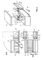
- a barrier is shown for Treppenabschottung.
- the Automatic Barrier Vertical Rotatable (TAB TAO) consists of a barrier body with closed cell Rubber seal 1 and two on one side Barrier body applied liquid-tight wedges 2.
- the wedges 2 are used in freestanding barrier without Wall connection of centering and stabilization.
- the wedges 2 would be at a wall connection of an additional Serve sealing.
- the barrier body consists of four flat components, which in the manner of a framework so connected to each other, that their rubber seals 1 in lie a plane, wherein the flat components a form a closed cross section with extensions. By the closed cross-section is a closed area a subsoil, while the extensions to the rotatable mounting of the barrier body 1 serve.
- a rotary joint with arm third arranged at two corners in the open position below of the barrier body 1 at two corners in the open position below of the barrier body 1 at two corners.
- the swivel joints are on the ground on each a bottom plate 4 firmly screwed.
- On the floor plates 4 are each two vertical L profiles 5 with Sump seals 6.
- the horizontal area of the Base plates 4 and the vent seals 6 and the vertical profiles 7 are with a High chemical resistant two-component sealant 8 circumferentially primed on Tiokol polysulfide (Adhesive) and liquid-tight glued and sealed.
- the barrier body 1 is about its lower vertices. 9 rotatably mounted.
- the barrier body 1 can optionally with and be equipped without closure flap 17.
- the Abdgurfedern 11 are in the open position of the Barrier body 1 stretched.
- the barrier body 1 is by means of a working and Damping cylinder 12 in a damped rotary motion pivotable. In the open position is the work and Dämpfzylinder 12 in about 30 ° - 60 ° position inclined to above. In the working path, a rotation of about 90 ° to Underground.
- the release plates touch 13th on the barrier body 1 screwed to the ground Impulse buoyancy safeguards 14.
- the trigger plate 13 at the respective Caster roller lever of the impulse buoyancy protection 14 takes place an automatic locking of the barrier body 1 to Underground.
- the release plates 13 and the Impulsetztriebsrion 14 can optionally within and be mounted outside of the barrier body 1.
- the buoyancy backups 14 compress with the Barrier body 1 all seals in horizontal and vertical area and secure the barrier body 1 permanently against buoyancy.
- the O-shaped part of the Barrier body 1 can optionally with and without the liquid tight screwed closure flap 17 operate. It creates an automatically closed Barrier for liquids and granules.
- the provision of the barrier body 1 in the vertical Opening position is optionally manually by hand, pneumatic or electropneumatic.
- the impulse buoyancy backups 14 per attachable hand lever 21 in the 0 dead center position pressed.
- the barrier body 1 by hand the horizontal pivoted in the open position.
- the Opening position is in each case the Abdrückfeder 11 tensioned and the locking and release devices 10 locked the barrier body 1.
- FIG. 5 shows a barrier for surface sealing.
- the Automatic Barrier Area Seal (TAB FA) consists of a barrier body with circumferential closed cell rubber seal 1.
- a Swivel with arm 3 attached At a lowermost point of the barrier body 1 is a Swivel with arm 3 attached.
- the swivel is on Underground or wall firmly screwed.
- Of the Barrier body 1 is rotatable about its corner point 9 stored.
- the Abdgurfeder 11 is in the open Position of the barrier body 1 stretched.
- the barrier body 1 is by means of a working and Damping cylinder 12 in a damped rotary motion pivotable. In the open position is the work and Dämpfzylinder 12 in about 30 ° - 60 ° position inclined to above. In the working path, a rotation of about 90 ° to Underground or wall.
- the barrier body 1 Upon release of the locking and release device 10th pushes the Abd Wegfeder 11 the barrier body 1 in a Rotation. Is the barrier body 1 in the approximate horizontal closed position pivoted, touches the Impulse buoyancy protection 14 the underground.
- the impulsee buoyancy protection 14 By the defined contact of the castor lever of the Impulse buoyancy protection 14 is an automatic Locking of the barrier body 1 in the bottom slot 22nd
- the swivel arm of the Impulsetztriebs felicit 14th an L-tongue 23 on.
- the L-tongue 23 pivots through the 90 ° rotation in the bottom slot 22 and pulls the Barrier body 1 to the underground.
- the impulse buoyancy protection 14 compresses with the Barrier body 1 all circumferential seals and secures the barrier body permanently against buoyancy. It arises an automatically closed barrier for liquids and granules.
- the provision of the barrier body 1 in the upper Opening position is optionally manually by hand, pneumatic or electropneumatic.
- the manual Reset is the impulse buoyancy protection 14 by hand pressed with hand lever 21 in the 0-dead center position. After that is the barrier body 1 by hand from the bottom into the pivoted upper position.
- the Abdschreibfeder 11 tensioned and the locking and Tripping device 10 locks the barrier body 1 in open position.
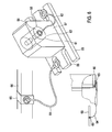
- the rotary joint 3 is preferably made of solid steel.
- the massive design allows very large forces be recorded.
- the bottom plate 55 is provided with four slotted slots 56 provided, which is an assembly and alignment of the joint enable.
- the condyle 57 is provided with a highly accurate bore 58 Mistake.
- the high-precision bore 58 is parallel to Bottom plate 55 is arranged. Thus stands the Barrier body 1 in opening position vertically.
- the high accuracy bore 58 also has an angle of 90 ° to the longitudinal axis of the bottom plate 55. This is because the line of movement also on the closure line.
- a propeller shaft 59 In the high-precision bore 58 is a propeller shaft 59 with threaded holes arranged on both sides on both sides fitted.
- the length of the propeller shaft 59 is 1/10 mm longer than the thickness of the condyle 57.
- the joint space 61 between the condyle 57 and Cardan shaft 59 is very small with 1/10 mm. This very much low joint space 61 is filled with a grease-copper-graphite filling 62 provided. By the very small Joint clearance also closes the barrier body 1 long lengths (for example 6000 mm) almost exactly.
- the Grease copper graphite filling 62 ensures a low-wear operation of the joint. The fat percentage lubricates permanently. The copper content prevents this "Eating" the two steel parts.
- the graphite component secures the permanent static dissipation between Cardan shaft and condyle.
- connection cable 63 is at both ends with Lugs provided and connects the articulated arm 60 with the joint bottom plate 55. This ensures that between articulated arm with barrier body and bottom plate different electrical potentials arise.
- the Connecting cable 64 connects the joint bottom plate 55 with the connection clip 65 of the equipotential busbar 66th This ensures that between the barrier and the grounded equipotential bonding no different Potentials can arise. Different potentials can lead to an electrostatic charge and subsequently lead to a spark discharge, which in potentially explosive atmospheres in connection with flammable gas-air mixtures causes an explosion.
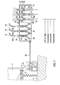
- a mechanical cable switch is shown.
- a shift cable 25 is fixed rollers 26 and idler 27 stretched.
- the fixed rollers 26 are on Blocks firmly connected to the housing 24.
- the Losrollen 27 are attached to guide pins 29. All fixed rollers 26 and all Losrollen 27 are with 30 ° shells 28 against the Jumping off the steel cable 25 secured.
- the guide pins 29 are movably mounted in guide sleeves 30.
- the cable 31st attached at the spring-loaded guide pin 29a.
- the cable may e.g. in an interior of a Building or any other place ends and train at the Pull the shift cable 25 into the interior of the housing 24.
- the shift cable 25 is at one end with the Trigger cable 32 connected.
- the hook of the Locking and release device 10 moves outwards and the role in Schwenkgelenkarm 3 is released.
- the Abdrückfeder 11 pivots the barrier body 1 in the Rotary movement and automatic closure of the barrier he follows.
- the spring-loaded guide pin 29b is also a Cable 31 attached.
- the cable could e.g. in the Outside of a building lead or at any another place and train in the shift cable 25 in the Pull the interior of the housing 24.
- the shift cable 25 is connected at one end to the trigger cable 32.
- the spring loaded guide pin 29c is also on attached to a cable 31.
- the cable could e.g. at a float switch, multiple energy switch or Any other place ends and train the shift cable 25 in the interior of the housing 24 pull.
- Of the Shift cable 25 is at one end with the release cable 32 connected.
- the Abdrückfeder 11 pivots the barrier body 1 in the rotational movement and the automatic closure of the barrier takes place.
- a pneumatic cylinder 36th appropriate on the guide pin 29f.
- pneumatic external control lowers the piston rod of the pneumatic cylinder 36 with the Guide pin 29f and it will train on the shift cable 25th exerted, which is in the interior of the housing 24th draws.
- the shift cable 25 is at one end with the Trigger cable 32 connected.
- the hook of the Locking and release device 10 moves outwards and the role in Schwenkgelenkarm 3 is released.
- the Abdrückfeder 11 pivots the barrier body 1 in the Rotary movement and automatic closure of the barrier he follows.
- the total number of trigger elements e.g. Cables 31, Guide pin 29, etc. is variable and can vary depending on Case of application combined and put together. in the In some cases, the system even allows only one Magnets 34 directly in place of the locking and Release device 10 to install. The function of Barrier is hereby also guaranteed.
- a multiple power switch is shown.
- the multiple energy switch is preferably the deepest Point of a room or gates and doors to be protected taken in the floor. All supply lines can concealed, for example in a protective jacket, im Underground are laid. In the wall area can optionally a surface mounting or flush mounting of the Multiple power switch as well as the supply lines respectively.
- the multiple energy switch comprises a housing 38 with a removable, heavy-load-drive hole cover 39.
- the Hole cover 39 is by L-webs 40 against slipping secured.
- the multiple energy switch points inside the case 38 a float 41 on.
- the float 41 is at one Shaft with bearings 42 rotatably mounted.
- the housing 38 has on the shaft side five liquid-tight cable and Tube entries 43 on.
- a vibrating probe 49 In addition to the float 41 is in the housing 38 of the Multiple energy switch a vibrating probe 49 arranged. By the ingress of liquids or granules in the housing 38 touch these substances upon reaching a certain level, the vibrating probe 49th The tuning fork of the Oscillating probe 49 thereby changes its vibration behavior. This leads to the triggering of the vibrating probe 49, i. to the issue an electrical signal. This electrical signal will tapped at the output of the vibrating probe and for triggering the closing process of a barrier used.
- the electric For example, signal can be sent directly to magnets, Solenoid valves, central control stations or equivalent Actuators of a mechanical cable switch to get redirected.
- a likewise arranged in the housing 38 non-contact Proximity switch with radio transmitter 45 allows a trouble-free work even under rough conditions.
- Radio transmitter needs within a radius of 20 m none Electrical installation. This eliminates extensive Construction work.
- the data can be read directly on magnets, Solenoid valves or corresponding actuators of a mechanical pulley switch.
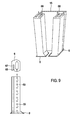
- a sump seal is one made of a permanently elastic Material, for example, a polymer manufactured Profile tube with an elongated cavity and a A plurality of projecting into the cavity Zu Kunststoffbohrungen 69th
- the supply air holes 69 bend on the inside of the seal Heat accumulation before and ensure the safe dissipation of Heat up.
- primers especially for absorbent substrates e.g., concrete
- primers for non-absorbent Substrates e.g., metal and closed cell gum
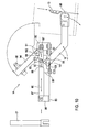
- Fig. 10 is a Impulsiertriebs rejoin in the open position and in Fig. 11 the same impulse buoyancy protection in the closed position.
- the impulse buoyancy protection 14 comprises a base plate 85 with bearing block 86, on which a gas pressure cylinder 87 is arranged is.
- the gas pressure cylinder 87 is a permanent Provided gas pressure filling.
- the piston rod 88 is in the gas pressure cylinder 87th retracted.
- the gas pressure cylinder 87 is through the Adjusting screw 89 held parallel to the base plate 85 and thus lies in a horizontal dead center 90.
- the Receiving bore in the bearing block 86, the gas pressure cylinder 87, the piston rod 88, the front and rear pivot plate 91 and the lower pivot axis pivot bracket 97 are in one Line, namely in the horizontal dead center 90th
- the piston rod of the gas pressure cylinder 87 presses pressurized with up to 3000N in line Bearing bore 87 to lower axis of rotation 97.
- Piston rod 88 are further rotatably attached to the front and rear pivot plate 91 with welded Pipe tongue 92 and the nose bar 93rd
- the swing arm 94 At the second end of the nose bar 93, the swing arm 94 attached. On the swing arm 94 is a height-adjustable Ball screw 95 screwed. The swing arm 94 is on the Swivel bracket 96 rotatably mounted.
- the release plate 13 on the barrier body pivots from above Underground. In the downward movement that touches Release plate 13, the caster with freewheel reset 89.
- the castor with free wheel return 89 is rotatably mounted on the caster lever 16.
- the Caster lever 16 is in the pivot point 99 at the Base plate 85 stored.
- the caster lever 16 is of the tension spring 100 stretched.
- On caster lever 16 is a Round iron 101 arranged transversely below the piston rod 88. The entire system is in tense rest position in horizontal dead center line 90.
- the pressurized piston rod 88 rotates the front and rear pivot plate 91 and the nose latch 93 upwards.
- the nose bar 93 is now about the upper axis of rotation of the Swivel bracket 102 pressed.
- the pivot arm 94 pivots to incoming barrier body 1.
- the height-adjustable Ball screw 95 is seated on the barrier body 1.
- the Ball screw 95 sets a low-wear and low-friction Pressing path on the barrier body 1 back. Is the front one and rear pivot plate 91 and the upper axis of rotation of Nose bar 93 and the lower axis of rotation of the pivoting bracket 97 are in a vertical line. Thus arises the vertical dead center line 103.
- the automatic closing process is finished and the Barrier is pressed and secured against buoyancy.
- the receiving bore in the bearing block 86, the gas cylinder 87, the piston rod 88, the front and rear pivot plate 91 and the lower pivot axis pivot bracket 97 are in one Line, namely in the horizontal dead center 90th
- the Barrier is open.
- a pulse thrust adjuster is shown in the open position and in Fig. 13, the same pulse thrust adjuster in the closed position.
- the pulse shear 19 comprises a base plate 85 with Bearing 86, on which a gas pressure cylinder 87 arranged is.
- the gas pressure cylinder 87 is a permanent Provided gas pressure filling.
- the piston rod 88 of the gas pressure cylinder 87 presses pressure accumulated up to 3000 N in line Bearing bore 87 to lower axis of rotation 97.
- Piston rods 88 are also the front and rear L-pivoting plate 84 with welded pipe tab 92 and the Push rod rotatably mounted with pointed piston 83.
- the push rod is attached with pointed piston 83.
- the front and the rear L-pivot plate 84 are with a continuous end pin for vertical dead center 104 provided.
- the receiving bore in the bearing block 86, the gas cylinder 87, the piston rod 88, the front and the rear L-pivoting plate 84 and the lower axis of rotation of the pivot bracket 97 lie in a line, namely in the horizontal Dead center line 90.
- the trigger plate 13 on the barrier body 1 pivots with the Barrier body 1 from top to bottom. In the Downward movement touches the release plate 13 the Caster with freewheel return 98.
- the castor with freewheel return 98 is rotatable on Caster lever 16 stored.
- the caster lever 16 is mounted at the pivot point 99 on the base plate 85. Of the Caster lever 16 is tensioned by tension spring 100. At the Caster lever 16 is a round iron 101 transversely below the Piston rod 88 is arranged.
- the entire system is in tense rest position in horizontal dead center line 90.
- the pressurized piston rod 88 rotates the front and rear L-pivot plate 84 and pushes the push rod with Pointed piston 83 forward.
- the push rod with pointed piston 83 is now pushed into the centering sleeve 18.
- the summit the pointed piston 83 allows safe insertion into the Centering sleeve 18.
- the penetrated pointed piston 83 centers both barrier bodies 1a, 1b in vertical as well horizontal direction and squeezes all horizontal and vertical seals.
- the receiving bore in the bearing block 86, the gas cylinder 87, the piston rod 88, the front and rear L-pivot plate 84 and the lower pivot axis pivot bracket 97 are in one Line, namely in the horizontal dead center 90th
- the Barrier is open.
- An acoustic warning signal (114) (eg siren) is applied to terminals 17 - 18.
- An external optical signal (115) can be applied to terminals 5 - 6.
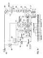
- the latching release switch S0 (116) is closed during operation. There is electricity flowing.
- the acknowledgment button S1 (117) must be pressed (acknowledgment that is not dangerous).
- the relay contactor K1 (118) is energized during operation. Fire alarm panel can be placed on terminals 3 - 4. If there is no BMZ, 3 - 4 can be bridged. For example, liquid probe can be placed on terminals 15 - 16 (120). If no fluid probe is present, 15 -16 can be bridged.
- K1 is the relay contactor (121) with terminals 11 -12 -14 (123) for switching the warning devices.
- K2 is the time relay contactor (122) with terminals 15-6-18 (106) for time-shifted switching (shutdown) of the solenoid valve coil (108).
- L1 and F1 fuse (105) are live.
- Relay contactor K1 (121 - 123) drops out.
- Warning signals (horn 114 and lamps 112, 115) are in operation.
- Solenoid valve coil 108 is still tightened, the barrier (1) still open.
- time relay K2T (122 - 106) drops out.
- the solenoid 108 is de-energized, falls off and the barrier (1) closes.
- L1 and F1 fuse (105) are live. It was tripped by eg switch S0 (116), BMZ (119), probe (120). K1 (123-121) and K2T (106-122) have dropped. The solenoid valve spool (108) has dropped and is de-energized. The green power indicator (109) goes off. Visual and audible warnings (114, 112, 115) are in operation. The barrier (1) is closed.
- a pneumatic control is shown.
- the pneumatic control becomes necessary when barriers with rotated large or large dimensions automatically and to be secured against buoyancy.
- the Pneumatic control offers great ease of use and is in all operating states of the barrier ready for use.
- the air battery buffer tank stores and buffers from the Compressed air network from compressor pneumatic power and the even with short-term power failure.
- pneumatic control Another big advantage of the pneumatic control is the Optionally electropneumatic operation or pure pneumatic operation (also emergency operation).
- the barrier and impulse buoyancy protection becomes more open Location kept.
- the pneumatic pressure is now on the piston side of the Impulse buoyancy protection (81) and the barrier is locked and secured against buoyancy.
- the barrier is locked against buoyancy and locked is closed.
- the release plate (13) touches the caster lever on the 3 / 2way tilting plunger valve and triggers a control impulse. From the 3/2-way tilt-roll valve, the air flows to the 5/2-way valve (80). From the 5/2-way valve (80), the air now flows into the impulse buoyancy protection (81).
- the pneumatic pressure is now on the piston side of the Impulse buoyancy protection (81) and the barrier is locked and secured against buoyancy.
- the barrier is secured against buoyancy, locked and is closed.
Landscapes
- Engineering & Computer Science (AREA)
- Structural Engineering (AREA)
- Architecture (AREA)
- Civil Engineering (AREA)
- Fluid-Damping Devices (AREA)
- Buildings Adapted To Withstand Abnormal External Influences (AREA)
- Socks And Pantyhose (AREA)
- Road Signs Or Road Markings (AREA)
- Pressure Vessels And Lids Thereof (AREA)
- Connector Housings Or Holding Contact Members (AREA)
- Building Environments (AREA)
Abstract
Description
- Fig. 1
- Barriere zur Türabschottung, einteilig
- Fig. 2
- Barriere zur Türabschottung, zweiteilig
- Fig. 3
- Barriere zur Tür- und Treppenabschottung
- Fig. 4
- Barriere zur Treppenabschottung
- Fig. 5
- Barriere zur Flächenabdichtung
- Fig. 6
- Elektrostatisch ableitfähiges Drehgelenk
- Fig. 7
- Sicherheitsseil
- Fig. 8
- Mehrfachenergieschalter
- Fig. 9
- Schlotdichtung
- Fig. 10
- Impulsauftriebssicherung in offener Stellung
- Fig. 11
- Impulsauftriebssicherung in Schließstellung
- Fig. 12
- Impulsschubspanner in offener Stellung
- Fig. 13
- Impulsschubspanner in Schließstellung
- Fig. 14
- Elektrosteuerung
- Fig. 15
- Pneumatiksteuerung
- Hydraulikrohreinführung 44 z.B. zur Auslösung eines mechanischen Seilzugschalters zur Betätigung der Feststellund Auslösevorrichtung 10 durch das Hydraulikventil 52,
- Berührungsloser Näherungsschalter mit Funksignal 45 zur digitalen Weiterverarbeitung ereignisabhängig bereitgestellter Signale,
- Seilzug 46 zur Auslösung eines mechanischen Seilzugschalters zur Betätigung der Feststell- und Auslösevorrichtung 10,
- Pneumatikschlaucheinführung 47 zur Ansteuerung der Pneumatiksteuerung eines mechanischen Seilzugschalters durch das Pneumatikventil 51,
- Elektrokabeleinführung 48 zur Weiterleitung elektrischer Signale von Schwingsonde 49 und Endlagenschalter 50
An Sicherung F1 (105) liegt Spannung an.
Das Zeitrelais K2T (106) ist angezogen (siehe 122).
Feinsicherung F2 (107) und Magnetventil mit Spule (108) führen Spannung.
Das Magnetventil (108) ist angezogen.
H1 grüne Betriebsbereitschaftsanzeige (109) leuchtet.
Die Klemme 11 und 12 ist gebrückt, und kann mit einer Lichtschranke (110) belegt sein.
Die Klemmen 7 8 9 und 10 sind für externe Positionsschalter (z.B. Zustandsanzeige) .
Sollten keine externen Positionsschalter gewünscht, so ist Klemme 7 - 8 gebrückt.
An Klemme 2 zu N ist das optische Warnsignal (112) (z.B. rote Lampe) aufgeschaltet.
Feinsicherung F3 (113) vor akustischem Warnsignal führt Spannung.
An Klemme 17 - 18 ist ein akustisches Warnsignal (114) (z.B. Sirene) aufgelegt.
An Klemme 5 - 6 kann ein externes optisches Signal (115) aufgelegt werden.
Der rastende Auslöseschalter S0 (116) ist im Betrieb geschlossen. Es fließt Strom.
Der Quittiertaster S1 (117) muss gedrückt sein (Quittierung das keine Gefahren anliegen).
Der Relais- Schütz K1 (118) ist im Betrieb angezogen.
Auf Klemme 3 - 4 kann Brandmeldezentrale aufgelegt werden.
Wenn keine BMZ vorhanden, kann 3 - 4 gebrückt werden.
Auf Klemme 15 - 16 (120) kann z.B. Flüssigkeitssonde aufgelegt werden.
Wenn keine Flüssigkeitssonde vorhanden, kann 15 -16 gebrückt werden.
K1 ist der Relaisschütz (121) mit den Klemmen 11 -12 -14 (123) zum Schalten der Warneinrichtungen.
K2 ist der Zeit-Relaisschütz (122) mit den Klemmen 15 - 6 - 18 (106) zum zeitversetzten Schalten (Abschalten) der Magnetventilspule (108).
Relaisschütz K1 (121 - 123) fällt ab.
Warnsignale (Hupe 114 und Lampen 112, 115) sind in Betrieb. Magnetventilspule108 ist noch angezogen, die Barriere (1) noch geöffnet.
Nach eingestellter Zeit (z.B. 1Minute) fällt Zeitrelais K2T (122 - 106) ab.
Die Magnetspule 108 wird stromlos, fällt ab und die Barriere (1) schließt.
Es erfolgte eine Auslösung durch z.B. Schalter S0 (116), BMZ (119), Sonde (120).
K1 (123 - 121) und K2T (106 - 122) sind abgefallen.
Die Magnetventilspule (108) ist abgefallen und stromlos.
Die Betriebsbereitschaftsanzeige Grün (109) erlischt.
Optische und akustische Warnsignale (114, 112, 115) sind in Betrieb.
Die Barriere (1) ist geschlossen.
Die Barriere (1) ist geschlossen.
Vom Absperr- und Rückschlagventil (82 strömt Luft in alle Versorgungsleitungen (72).
Von Versorgungsleitung (72) strömt Luft in das 5/2Wegeventil (77).
Vom 5/2Wegeventil (77) strömt Luft in das spannungsführende Magnetventil (76).
Vom spannungsführenden Magnetventil (76) strömt Luft in beide Logikelemente OG (75).
Vom oberen Logikelement-Oderglied (75) strömt Luft in das Drosselrückschlagventil (74).
Vom Drosselrückschlagventil (74) strömt die Luft nun in den Arbeits- und Dämpfzylinder (73).
Der Pneumatikdruck liegt auf der Kolbenstangenseite des Arbeits- und Dämpfzylinder (73).
Vom unteren Logikelement-Oderglied (75) strömt Luft in das 5/2Wegeventil (80).
Vom 5/2Wegeventil (80) strömt die Luft nun in die Impulsauftriebssicherung (81).
Die Kolbenstangenseite der Impulsauftriebssicherung (81) hat Druckluft =geöffnet.
Vom Absperr- und Rückschlagventil 82 strömt Luft in alle Versorgungsleitungen (72).
Von Versorgungsleitung (72) strömt Luft in das 5/2Wegeventil (77).
Vom 5/2Wegeventil (77 strömt Luft in das spannungsfreie Magnetventil (76).
Vom spannungsfreien Magnetventil (76) strömt Luft in das Drosselrückschlagventil (74).
Vom Drosselrückschlagventil (74) strömt die Luft nun in den Arbeits- und Dämpfzylinder (73).
Der Pneumatikdruck liegt nun auf der Kolbenseite des Arbeits- und Dämpfzylinder (73) an und die Barriere wird geschlossen.
Vom Absperr- und Rückschlagventil (82 strömt Luft in alle Versorgungsleitungen (72).
Von Versorgungsleitung (72) strömt Luft in den Wahlschalter3/2WegeventilNotbetrieb (78).
Durch Betätigung des Wahlschalter3/2Wege-Notbetrieb strömt Luft zu 5/2Wegeventil 77.
Vom 5/2Wegeventil (77) strömt Luft auf beide Logikelemente Oderglieder (75).
Vom 5/2Wegeventil (80) strömt die Luft nun in die Impulsauftriebssicherung (81).
Die Kolbenstangenseite der Impulsauftriebssicherung (81) hat Druckluft =öffnet.
Vom Drosselrückschlagventil (74) strömt die Luft nun in den Arbeits- und Dämpfzylinder (73).
Der Pneumatikdruck liegt nun auf der Kolbenstangenseite des Arbeits- und Dämpfzylinder (73)an und die Barriere öffnet.
Vom Absperr- und Rückschlagventil (82 strömt Luft in alle Versorgungsleitungen (72).
Von Versorgungsleitung (72) strömt Luft in den Wahlschalter3/2WegeventilNotbetrieb (78).
Durch Betätigung des Wahlschalter3/2Wege-Notbetrieb strömt Luft zu 5/2Wegeventil 77.
Vom 5/2Wegeventil (77) strömt Luft in das spannungsfreie Magnetventil (76).
Vom spannungsfreien Magnetventil (76) strömt Luft in das Drosselrückschlagventil (74).
Vom Drosselrückschlagventil (74) strömt die Luft nun in den Arbeits- und Dämpfzylinder (73).
Der Pneumatikdruck liegt nun auf der Kolbenseite des Arbeits- und Dämpfzylinder (73) an und die Barriere wird geschlossen.
Vom 3/2WegeKipprollenventil strömt die Luft zum 5/2Wegeventil (80).
Vom 5/2Wegeventil (80) strömt die Luft nun in die Impulsauftriebssicherung (81).
- 1
- Barrierenkörper
- 2
- Keil
- 3
- Drehgelenk mit Arm
- 4
- Bodenplatte
- 5
- L-Profil
- 6
- Schlotdichtung
- 7
- Wandanschlussprofil
- 8
- Flüssigkeitsdichte Tiokol-Polysulfid Fuge
- 9
- Drehpunkt
- 10
- Auslöse- und Feststellvorrichtung
- 11
- Abdrückfeder
- 12
- Arbeits- und Dämpfzylinder
- 13
- Auslöseblech
- 14
- Impulsauftriebssicherung mit Schwenkrollenarm
- 15
- Konisches U-Profil
- 16
- Schwenkrollenhebel
- 17
- Verschlussklappe
- 18
- Zentrierhülse
- 19
- Impulsschubspanner
- 20
- Schwenkrollenhebel
- 21
- Handrückstellhebel
- 24
- Gehäuse
- 25
- Schaltseilzug
- 26
- Festrolle mit Bock
- 27
- Losrolle
- 28
- 30°Schale-Seilabsprungsicherung
- 29
- Führungsbolzen
- 30
- Führungshülse
- 31
- Seilzug
- 32
- Auslöseseilzug
- 33
- Stahlgewicht
- 34
- Elektrischer Haftmagnet
- 35
- Hydraulikzylinder
- 36
- Pneumatikzylinder
- 38
- Gehäuse
- 39
- Lochdeckel
- 40
- L-Stege
- 41
- Schwimmer
- 42
- Welle mit Lagern
- 43
- Kabeleinführungen, druckfest
- 44
- Hydraulikrohreinführung
- 45
- Berührungsloser Näherungsschalter mit Funksender
- 46
- Seilzug
- 47
- Pneumatikschlaucheinführung
- 48
- Elektrokabeleinführung
- 49
- Schwingsonde
- 50
- Endlagenschalter
- 51
- Pneumatikventil
- 52
- Hydraulikventil
- 55
- Bodenplatte
- 56
- Langlochschlitz
- 57
- Gelenkkopf
- 58
- Hochgenaue Bohrung
- 59
- Gelenkwelle.
- 60
- Gelenkarm
- 61
- Gelenkzwischenraum
- 62
- Fett-Kupfer-Graphit Füllung
- 63
- Verbindungskabel
- 64
- Verbindungskabel
- 65
- Anschlussschelle
- 66
- Potentialausgleichsschiene
- 67
- Klemmprofil
- 68
- Dichtlippen
- 70
- Luftakku - Pufferbehälter
- 71
- Wartungseinheit (Filter, Drossel, Manometer)
- 72
- Versorgungsleitung
- 73
- Arbeits- und Dämpfzylinder
- 74
- Drosselrückschlagventil
- 75
- Logikelement (Oderglied)
- 76
- Magnetventil z.B.MFH-6-1/8-B
- 77
- 5/2-Wegeventil z.B. VL-5-1/8-B
- 78
- Wahlschalter 3/2 Wegeventil Notbetrieb
- 79
- 3/2Wege Ventil mit Schwenkrollenhebel
- 80
- 5/2Wegeventil z.B. J-5/2-1/8-B
- 81
- Impulsauftriebssicherung
- 82
- Rückschlag- und Absperrventil
- 83
- Schubstange mit Spitzkolben
- 84
- Vorderes und hinteres L-Schwenkblech
- 85
- Grundplatte
- 86
- Lagerbock
- 87
- Gasdruckzylinder
- 88
- Kolbenstange
- 89
- Einstellschraube
- 90
- Waagerechte Totpunktlage
- 91
- Vorderes und hinteres Schwenkblech
- 92
- Aufgeschweißte Rohrzunge
- 93
- Nasenriegel
- 94
- Schwenkarm
- 95
- Höhenverstellbare Kugelschraube
- 96
- Schwenkbock
- 97
- Untere Drehachse des Schwenkbockes
- 98
- Schwenkrolle mit Freilaufrückstellung
- 99
- Drehpunkt des Schwenkrollenhebels
- 100
- Zugfeder
- 101
- Rundeisen quer
- 102
- Obere Drehachse des Schwenkbockes
- 103
- Senkrechte Totpunktlinie
- 104
- Endlagenbolzen für senkrechten Totpunkt
- 105
- F1 Sicherung
- 106
- Zeitrelais K2T (Arbeits- u Steuerkreis auch 121)
- 107
- F2 Feinsicherung
- 108
- Magnetventilspule
- 109
- H1 Grüne Betriebsbereitschaftsanzeige
- 110
- Lichtschranke (oder Brücke)
- 111
- Externe Positionsschalter
- 112
- Externe Leuchtmittel
- 113
- F3 Feinsicherung für akustisches Warnsignal
- 114
- Externes akustisches Warnsignal (z.B. Hupe)
- 115
- Externes Leuchtmittel (Lampe)
- 116
- S0 Rastender Auslösetaster
- 117
- S1 Quittiertaster
- 118
- Relaisschütz K1 (siehe auch 121)
- 119
- BMZ (oder Brücke)
- 120
- Sonde (oder Brücke)
- 121
- K1 Relaisschütz (siehe auch 118)
- 122
- K2T Zeitrelaisschütz (siehe auch 106)
Claims (10)
- Barriere zum Schutz vor ein- und auslaufenden Stoffen, umfassend einen Barrierenkörper (1) mit einem Dichtelement zur horizontalen Abdichtung des Barrierenkörpers gegen einen Untergrund, mindestens eine an dem Barrierenkörper (1) angeordnete Keildichtung (2) zur vertikalen Abdichtung des Barrierenkörpers (1) gegen eine Barrierenaufnahme (5,15), mindestens eine Barrierenaufnahme (5,15) mit einem Dichtsitz zur Aufnahme der oder einer Keildichtung (2) und mindestens ein den Barrierenkörper (1) mit einem wählbaren Fixpunkt um eine horizontale Achse schwenkbar verbindendes Drehgelenk (3).
- Barriere nach Anspruch 1, dadurch gekennzeichnet, dass der Barrierenkörper (1) aus mehreren flächigen Bauteilen besteht, wobei mehrere flächige Bauteile in der Art eines Fachwerks so miteinander verbunden sind, dass ihre Dichtelemente zur horizontalen Abdichtung des Barrierenkörpers (1) gegen einen Untergrund in einer Ebene liegen.
- Barriere nach Anspruch 1, dadurch gekennzeichnet, dass der Barrierenkörper (1) aus mehreren, nicht miteinander verbundenen flächigen Bauteilen besteht, die unabhängig voneinander schwenkbar gelagert sind und jeweils in eine Position schwenkbar sind, in der die einzelnen flächigen Bauteile dergestalt miteinander in Wirkverbindung treten, dass sie gemeinsam eine geschlossene Barriere bilden.
- Barriere nach einem der vorhergehenden Ansprüche, dadurch gekennzeichnet, dass die Barrierenaufnahme (5,15) einen langgestreckten Schlitz mit einer zur Vertikalen geneigten Flanke mit einem Dichtmittel (6) zur vertikalen Abdichtung des Barrierenkörpers (1) aufweist, wobei der Neigungswinkel der Flanke dem der Keildichtung (2) des Barrierenkörpers (1) entspricht.
- Barriere nach Anspruch 4, dadurch gekennzeichnet, dass das Dichtmittel (6) eine Schlotdichtung ist.
- Barriere nach einem der vorhergehenden Ansprüche, dadurch gekennzeichnet, dass das Drehgelenk (3) zur Befestigung am Untergrund ausgebildet ist, so dass der Barrierenkörper (1) um einen möglichst tief liegenden Punkt schwenkbar ist.
- Elektrostatisch ableitfähiges Drehgelenk (3), umfassend eine Bodenplatte (55), einen auf der Bodenplatte (55) angeordneten Gelenkkopf (57) mit einer hochgenauen Bohrung (58), eine in der hochgenauen Bohrung (58) angeordnete Gelenkwelle (59) mit beidseitig stirnseitig angeordneten Gewindebohrungen zur stirnseitigen Befestigung eines Schwenkarms (60), eine den Gelenkzwischenraum (61) zwischen Gelenkkopf (57) und Gelenkwelle (59) ausfüllende Fett-Kupfer-Graphit-Füllung (62) sowie ein Verbindungskabel (63) mit beidseitig angeordneten Kabelschuhen, wobei die Gelenkwelle (59) und die Bodenplatte (55) durch das Verbindungskabel (63) elektrisch miteinander verbunden sind.
- Mechanischer Seilzugschalter, umfassend ein Gehäuse (24), in dem Gehäuse (24) mindestens eine Schalteinrichtung, die aus einer am Gehäuse (24) angebrachten Führungshülse (30), einem in der Führungshülse (30) beweglich gelagerten Führungsbolzen (29), einer an dem Führungsbolzen (29) angebrachten Losrolle (27) sowie einer am Gehäuse (24) angebrachten Festrolle (26) besteht, und einen mit einem Ende am Gehäuse (24) festgelegten, mit dem anderen Ende durch eine dafür vorgesehene Öffnung des Gehäuses (24) aus diesem heraus ragenden Schaltseilzug (25), wobei der Schaltseilzug (25) so um die Losrollen (27) und Festrollen (26) geführt ist, dass eine Verschiebung eines Führungsbolzens (29) in der Führungshülse (30) zum Einziehen des aus dem Gehäuse (24) ragenden Endes des Schaltseilzuges (25) in das Gehäuse (24) führt.
- Mehrfachenergieschalter, umfassend ein Gehäuse (38) mit einem Lochdeckel (39) und mindestens einer Durchführung für Kabel (43,48) oder Rohre (44) oder Schläuche (47) sowie eine Schwingsonde (49) oder/und einen berührungslosen Näherungsschalter (45) oder/und einen im Gehäuse (38) gelagerten Schwimmer (41), der mit einem ebenfalls im Gehäuse (38) angeordneten Seilzug (46) oder/und Pneumatikventil (51) oder/und Hydraulikventil (52) oder/und elektrischen Endlagenschalter (50) in Wirkverbindung steht.
- Arretierungseinrichtung zum Verstellen eines Schubbolzens (83) oder eines Schwenkarms (94) aus einer Öffnungsstellung in eine Schließstellung, umfassend eine Grundplatte (85) mit Lagerbock (86), einen an dem Lagerbock (86) gelenkig angeordneten Gasdruckzylinder (87), einen Schwenkrollenhebel (20) zum Schwenken des Gasdruckzylinders (87) aus der Öffnungsstellung, einen an der Kolbenstange (88) des Gasdruckzylinders (87) gelenkig angeordneten Hebelmechanismus (84,83,91,93), der mit einem Schubbolzen (83) oder einem Schwenkarm (94) in Wirkverbindung steht, wobei der Gasdruckzylinder (87) eine Kraft auf den Hebelmechanismus (84,83,91,93) ausübt, die in der Öffnungsstellung vom Hebelmechanismus (84,83,91,93) bewegungslos aufgenommen wird und die den Hebelmechanismus (84,83,91,93) betätigt, sobald der Gasdruckzylinder (87) aus der Öffnungsstellung geschwenkt wird, wodurch der Schubbolzen (83) bzw. der Schwenkarm (94) in die Schließstellung bewegt wird.
Priority Applications (4)
| Application Number | Priority Date | Filing Date | Title |
|---|---|---|---|
| EP04106168A EP1524369B1 (de) | 2004-11-29 | 2004-11-29 | Barriere zum Schutz vor ein- und auslaufenden Stoffen |
| AT04106168T ATE473326T1 (de) | 2004-11-29 | 2004-11-29 | Barriere zum schutz vor ein- und auslaufenden stoffen |
| DE502004011359T DE502004011359D1 (de) | 2004-11-29 | 2004-11-29 | Barriere zum Schutz vor ein- und auslaufenden Stoffen |
| DE102005007400A DE102005007400B4 (de) | 2004-11-29 | 2005-02-18 | Arretierungseinrichtung |
Applications Claiming Priority (1)
| Application Number | Priority Date | Filing Date | Title |
|---|---|---|---|
| EP04106168A EP1524369B1 (de) | 2004-11-29 | 2004-11-29 | Barriere zum Schutz vor ein- und auslaufenden Stoffen |
Publications (3)
| Publication Number | Publication Date |
|---|---|
| EP1524369A2 true EP1524369A2 (de) | 2005-04-20 |
| EP1524369A3 EP1524369A3 (de) | 2005-11-16 |
| EP1524369B1 EP1524369B1 (de) | 2010-07-07 |
Family
ID=34354661
Family Applications (1)
| Application Number | Title | Priority Date | Filing Date |
|---|---|---|---|
| EP04106168A Expired - Lifetime EP1524369B1 (de) | 2004-11-29 | 2004-11-29 | Barriere zum Schutz vor ein- und auslaufenden Stoffen |
Country Status (3)
| Country | Link |
|---|---|
| EP (1) | EP1524369B1 (de) |
| AT (1) | ATE473326T1 (de) |
| DE (2) | DE502004011359D1 (de) |
Cited By (7)
| Publication number | Priority date | Publication date | Assignee | Title |
|---|---|---|---|---|
| EP2460966A2 (de) * | 2010-12-06 | 2012-06-06 | Werner Thomas | Vorrichtung zum zumindest teilweisen Verschließen einer Öffnung eines Raumes |
| WO2016171616A1 (en) | 2015-04-21 | 2016-10-27 | Parafoil Design & Engineering Pte Ltd | A floodgate |
| CN115354956A (zh) * | 2022-09-21 | 2022-11-18 | 深圳市中航深亚智能科技有限公司 | 仓库用具有急停功能的电动型卷闸门及控制方法 |
| CN117589549A (zh) * | 2024-01-19 | 2024-02-23 | 浙江省辐射环境监测站(生态环境部辐射环境监测技术中心) | 基于复合式高精检测技术的氚自动提取制备装置及方法 |
| CN118434116A (zh) * | 2024-07-04 | 2024-08-02 | 易创智芯(西安)科技有限公司 | 一种具有分层防护功能的电磁屏蔽室 |
| CN119606271A (zh) * | 2025-01-21 | 2025-03-14 | 南京特沃斯清洁设备有限公司 | 一种模块化洗地机静音系统 |
| US12304288B2 (en) | 2023-06-12 | 2025-05-20 | Ford Global Technologies, Llc | Sealing system for vehicle closure system |
Citations (3)
| Publication number | Priority date | Publication date | Assignee | Title |
|---|---|---|---|---|
| CH681176A5 (de) | 1989-08-02 | 1993-01-29 | Zeiss Jena Veb Carl | |
| DE29506179U1 (de) | 1994-04-14 | 1995-06-22 | Scherer, Peter, 65555 Limburg | Vorrichtung zum flüssigkeitsdichten Verschließen von Gebäude-, Becken-, Schleusenöffnungen o.dgl. |
| DE19625477C1 (de) | 1996-06-26 | 1997-10-02 | Metallbau Heinz Ruland Gmbh | Flüssigkeitsbarriere zum dichten Abschluß des unteren Bereiches einer Maueröffnung oder dergleichen |
Family Cites Families (5)
| Publication number | Priority date | Publication date | Assignee | Title |
|---|---|---|---|---|
| DE4106269C2 (de) * | 1991-02-28 | 1993-10-21 | Schering Ag | Löschwasserbarriere |
| DE9112128U1 (de) * | 1991-09-28 | 1991-12-12 | Blobel Umwelttechnik GmbH, 8904 Friedberg | Vorrichtung zum bedarfsweisen flüssigkeitsdichten Absperren von Tür- oder Toröffnungen von Gebäuden oder baulichen Anlagen, insbesondere gegen Austritt von verseuchtem Löschwasser |
| DE19517241C2 (de) * | 1994-05-16 | 1997-05-22 | Werner Thomas | Vorrichtung zum Abschotten eines Raumes |
| DE29508533U1 (de) * | 1995-05-26 | 1995-09-07 | UBS-technik Umwelt- und Brandschutztechnik Kiepkowski + Schmidt oHG, 52531 Übach-Palenberg | Störfallbarriere zum flüssigkeitsdichten Verschließen von Tor- und Gebäudeöffnungen |
| DE19801057C1 (de) * | 1998-01-14 | 1999-03-04 | Andreas Maier Gmbh & Co | Spannvorrichtung |
-
2004
- 2004-11-29 EP EP04106168A patent/EP1524369B1/de not_active Expired - Lifetime
- 2004-11-29 AT AT04106168T patent/ATE473326T1/de active
- 2004-11-29 DE DE502004011359T patent/DE502004011359D1/de not_active Expired - Lifetime
-
2005
- 2005-02-18 DE DE102005007400A patent/DE102005007400B4/de not_active Expired - Lifetime
Patent Citations (3)
| Publication number | Priority date | Publication date | Assignee | Title |
|---|---|---|---|---|
| CH681176A5 (de) | 1989-08-02 | 1993-01-29 | Zeiss Jena Veb Carl | |
| DE29506179U1 (de) | 1994-04-14 | 1995-06-22 | Scherer, Peter, 65555 Limburg | Vorrichtung zum flüssigkeitsdichten Verschließen von Gebäude-, Becken-, Schleusenöffnungen o.dgl. |
| DE19625477C1 (de) | 1996-06-26 | 1997-10-02 | Metallbau Heinz Ruland Gmbh | Flüssigkeitsbarriere zum dichten Abschluß des unteren Bereiches einer Maueröffnung oder dergleichen |
Cited By (11)
| Publication number | Priority date | Publication date | Assignee | Title |
|---|---|---|---|---|
| EP2460966A2 (de) * | 2010-12-06 | 2012-06-06 | Werner Thomas | Vorrichtung zum zumindest teilweisen Verschließen einer Öffnung eines Raumes |
| WO2016171616A1 (en) | 2015-04-21 | 2016-10-27 | Parafoil Design & Engineering Pte Ltd | A floodgate |
| JP2018513929A (ja) * | 2015-04-21 | 2018-05-31 | パラフォイル・デザイン・アンド・エンジニアリング・プライベイト・リミテッドParafoil Design & Engineering Pte Ltd | 水門 |
| EP3286397A4 (de) * | 2015-04-21 | 2018-12-05 | Parafoil Design & Engineering Pte Ltd | Schleuse |
| CN115354956A (zh) * | 2022-09-21 | 2022-11-18 | 深圳市中航深亚智能科技有限公司 | 仓库用具有急停功能的电动型卷闸门及控制方法 |
| CN115354956B (zh) * | 2022-09-21 | 2024-05-31 | 深圳市中航深亚智能科技有限公司 | 仓库用具有急停功能的电动型卷闸门及控制方法 |
| US12304288B2 (en) | 2023-06-12 | 2025-05-20 | Ford Global Technologies, Llc | Sealing system for vehicle closure system |
| CN117589549A (zh) * | 2024-01-19 | 2024-02-23 | 浙江省辐射环境监测站(生态环境部辐射环境监测技术中心) | 基于复合式高精检测技术的氚自动提取制备装置及方法 |
| CN117589549B (zh) * | 2024-01-19 | 2024-04-05 | 浙江省辐射环境监测站(生态环境部辐射环境监测技术中心) | 基于复合式高精检测技术的氚自动提取制备装置及方法 |
| CN118434116A (zh) * | 2024-07-04 | 2024-08-02 | 易创智芯(西安)科技有限公司 | 一种具有分层防护功能的电磁屏蔽室 |
| CN119606271A (zh) * | 2025-01-21 | 2025-03-14 | 南京特沃斯清洁设备有限公司 | 一种模块化洗地机静音系统 |
Also Published As
| Publication number | Publication date |
|---|---|
| EP1524369A3 (de) | 2005-11-16 |
| ATE473326T1 (de) | 2010-07-15 |
| EP1524369B1 (de) | 2010-07-07 |
| DE502004011359D1 (de) | 2010-08-19 |
| DE102005007400B4 (de) | 2006-10-26 |
| DE102005007400A1 (de) | 2006-06-01 |
Similar Documents
| Publication | Publication Date | Title |
|---|---|---|
| WO2010012497A1 (de) | Türöffner mit sperrventil | |
| DE102010062449A1 (de) | Vorrichtung zum zumindest teilweisen Verschließen einer Öffnung eines Raumes | |
| CH644418A5 (de) | Absperrvorrichtung mit einem versenkbaren absperrpfosten. | |
| DE20013512U1 (de) | Sektionalhub- oder Falttor | |
| EP1029557A1 (de) | Rauchschutzabschluss | |
| EP1524369B1 (de) | Barriere zum Schutz vor ein- und auslaufenden Stoffen | |
| EP0754822B1 (de) | Vorrichtung zum Abschotten von Räumen; ohne Auslösemechanismus | |
| DE4008813A1 (de) | Fluessigkeitsschott fuer raeume | |
| DE2547818A1 (de) | Vorrichtung zum abdichten und schliessen von feuerschutzabschluessen fuer oeffnungen in einer wand oder decke | |
| DE102007010261B4 (de) | Vorrichtung zum selbsttätigen Schließen eines Fensterkippflügels zum Schutz vor eindringendem Wasser | |
| EP0003614B1 (de) | Feuerschutzabschluss zum Abdichten und Verschliessen von Öffnungen in Wänden und Decken | |
| EP0851083B1 (de) | Vertikalschiebefenster | |
| DE202005020194U1 (de) | Pendeltüre selbstschließend mit Fliegenschutzgitter | |
| DE4136479A1 (de) | Fluessigkeits- oder gasdichter abschluss an einer gebaeudeoeffnung | |
| DE3545057A1 (de) | Unfallschutzleiste | |
| AT8851U1 (de) | Vorrichtung zum automatischen schliessen eines kippfensters | |
| EP3696330A1 (de) | Verschlusssystem für schachtbauwerke | |
| DE10323682A1 (de) | Mechanische Schwenkbarriere zum abschotten von Räumen bei automatischer Funktionsweise | |
| EP1195179B1 (de) | Brand/Rauchschutztoranlage Bzw. Brand/Rauchschutztüranlage | |
| DE19915433A1 (de) | Absperrvorrichtung zum Absperren und/oder Freigeben von einem Fahrzeugparkplatz | |
| DE102016101562A1 (de) | Verschlussvorrichtung für eine Rückstausicherung und eine Rückstausicherung mit der Verschlussvorrichtung | |
| CH712389A2 (de) | Vorrichtung zur Verhinderung des Aufschwimmens von Tanks in Schutzbauwerken im Hochwasserfall. | |
| CH719433A2 (de) | Klappschott. | |
| DE2922134A1 (de) | Vorrichtung zum oeffnen eines verschlusselements, insbesondere eines garagentores o.dgl. | |
| CH716085A2 (de) | Klappschott. |
Legal Events
| Date | Code | Title | Description |
|---|---|---|---|
| PUAI | Public reference made under article 153(3) epc to a published international application that has entered the european phase |
Free format text: ORIGINAL CODE: 0009012 |
|
| AK | Designated contracting states |
Kind code of ref document: A2 Designated state(s): AT BE BG CH CY CZ DE DK EE ES FI FR GB GR HU IE IS IT LI LU MC NL PL PT RO SE SI SK TR |
|
| AX | Request for extension of the european patent |
Extension state: AL HR LT LV MK YU |
|
| RIC1 | Information provided on ipc code assigned before grant |
Ipc: 7E 02B 3/10 A Ipc: 7E 06B 9/02 B |
|
| PUAL | Search report despatched |
Free format text: ORIGINAL CODE: 0009013 |
|
| AK | Designated contracting states |
Kind code of ref document: A3 Designated state(s): AT BE BG CH CY CZ DE DK EE ES FI FR GB GR HU IE IS IT LI LU MC NL PL PT RO SE SI SK TR |
|
| AX | Request for extension of the european patent |
Extension state: AL HR LT LV MK YU |
|
| 17P | Request for examination filed |
Effective date: 20060316 |
|
| AKX | Designation fees paid |
Designated state(s): AT BE BG CH CY CZ DE DK EE ES FI FR GB GR HU IE IS IT LI LU MC NL PL PT RO SE SI SK TR |
|
| 17Q | First examination report despatched |
Effective date: 20070427 |
|
| GRAP | Despatch of communication of intention to grant a patent |
Free format text: ORIGINAL CODE: EPIDOSNIGR1 |
|
| GRAS | Grant fee paid |
Free format text: ORIGINAL CODE: EPIDOSNIGR3 |
|
| GRAA | (expected) grant |
Free format text: ORIGINAL CODE: 0009210 |
|
| AK | Designated contracting states |
Kind code of ref document: B1 Designated state(s): AT BE BG CH CY CZ DE DK EE ES FI FR GB GR HU IE IS IT LI LU MC NL PL PT RO SE SI SK TR |
|
| REG | Reference to a national code |
Ref country code: GB Ref legal event code: FG4D Free format text: NOT ENGLISH |
|
| REG | Reference to a national code |
Ref country code: CH Ref legal event code: EP |
|
| REG | Reference to a national code |
Ref country code: IE Ref legal event code: FG4D |
|
| REF | Corresponds to: |
Ref document number: 502004011359 Country of ref document: DE Date of ref document: 20100819 Kind code of ref document: P |
|
| REG | Reference to a national code |
Ref country code: NL Ref legal event code: VDEP Effective date: 20100707 |
|
| PG25 | Lapsed in a contracting state [announced via postgrant information from national office to epo] |
Ref country code: SI Free format text: LAPSE BECAUSE OF FAILURE TO SUBMIT A TRANSLATION OF THE DESCRIPTION OR TO PAY THE FEE WITHIN THE PRESCRIBED TIME-LIMIT Effective date: 20100707 |
|
| PG25 | Lapsed in a contracting state [announced via postgrant information from national office to epo] |
Ref country code: FI Free format text: LAPSE BECAUSE OF FAILURE TO SUBMIT A TRANSLATION OF THE DESCRIPTION OR TO PAY THE FEE WITHIN THE PRESCRIBED TIME-LIMIT Effective date: 20100707 Ref country code: NL Free format text: LAPSE BECAUSE OF FAILURE TO SUBMIT A TRANSLATION OF THE DESCRIPTION OR TO PAY THE FEE WITHIN THE PRESCRIBED TIME-LIMIT Effective date: 20100707 |
|
| REG | Reference to a national code |
Ref country code: IE Ref legal event code: FD4D |
|
| PG25 | Lapsed in a contracting state [announced via postgrant information from national office to epo] |
Ref country code: BG Free format text: LAPSE BECAUSE OF FAILURE TO SUBMIT A TRANSLATION OF THE DESCRIPTION OR TO PAY THE FEE WITHIN THE PRESCRIBED TIME-LIMIT Effective date: 20101007 Ref country code: PL Free format text: LAPSE BECAUSE OF FAILURE TO SUBMIT A TRANSLATION OF THE DESCRIPTION OR TO PAY THE FEE WITHIN THE PRESCRIBED TIME-LIMIT Effective date: 20100707 Ref country code: CY Free format text: LAPSE BECAUSE OF FAILURE TO SUBMIT A TRANSLATION OF THE DESCRIPTION OR TO PAY THE FEE WITHIN THE PRESCRIBED TIME-LIMIT Effective date: 20100707 Ref country code: IS Free format text: LAPSE BECAUSE OF FAILURE TO SUBMIT A TRANSLATION OF THE DESCRIPTION OR TO PAY THE FEE WITHIN THE PRESCRIBED TIME-LIMIT Effective date: 20101107 Ref country code: PT Free format text: LAPSE BECAUSE OF FAILURE TO SUBMIT A TRANSLATION OF THE DESCRIPTION OR TO PAY THE FEE WITHIN THE PRESCRIBED TIME-LIMIT Effective date: 20101108 |
|
| PG25 | Lapsed in a contracting state [announced via postgrant information from national office to epo] |
Ref country code: GR Free format text: LAPSE BECAUSE OF FAILURE TO SUBMIT A TRANSLATION OF THE DESCRIPTION OR TO PAY THE FEE WITHIN THE PRESCRIBED TIME-LIMIT Effective date: 20101008 Ref country code: SE Free format text: LAPSE BECAUSE OF FAILURE TO SUBMIT A TRANSLATION OF THE DESCRIPTION OR TO PAY THE FEE WITHIN THE PRESCRIBED TIME-LIMIT Effective date: 20100707 |
|
| PG25 | Lapsed in a contracting state [announced via postgrant information from national office to epo] |
Ref country code: IE Free format text: LAPSE BECAUSE OF FAILURE TO SUBMIT A TRANSLATION OF THE DESCRIPTION OR TO PAY THE FEE WITHIN THE PRESCRIBED TIME-LIMIT Effective date: 20100707 Ref country code: DK Free format text: LAPSE BECAUSE OF FAILURE TO SUBMIT A TRANSLATION OF THE DESCRIPTION OR TO PAY THE FEE WITHIN THE PRESCRIBED TIME-LIMIT Effective date: 20100707 |
|
| PLBE | No opposition filed within time limit |
Free format text: ORIGINAL CODE: 0009261 |
|
| STAA | Information on the status of an ep patent application or granted ep patent |
Free format text: STATUS: NO OPPOSITION FILED WITHIN TIME LIMIT |
|
| PG25 | Lapsed in a contracting state [announced via postgrant information from national office to epo] |
Ref country code: CZ Free format text: LAPSE BECAUSE OF FAILURE TO SUBMIT A TRANSLATION OF THE DESCRIPTION OR TO PAY THE FEE WITHIN THE PRESCRIBED TIME-LIMIT Effective date: 20100707 Ref country code: EE Free format text: LAPSE BECAUSE OF FAILURE TO SUBMIT A TRANSLATION OF THE DESCRIPTION OR TO PAY THE FEE WITHIN THE PRESCRIBED TIME-LIMIT Effective date: 20100707 Ref country code: IT Free format text: LAPSE BECAUSE OF FAILURE TO SUBMIT A TRANSLATION OF THE DESCRIPTION OR TO PAY THE FEE WITHIN THE PRESCRIBED TIME-LIMIT Effective date: 20100707 Ref country code: RO Free format text: LAPSE BECAUSE OF FAILURE TO SUBMIT A TRANSLATION OF THE DESCRIPTION OR TO PAY THE FEE WITHIN THE PRESCRIBED TIME-LIMIT Effective date: 20100707 Ref country code: SK Free format text: LAPSE BECAUSE OF FAILURE TO SUBMIT A TRANSLATION OF THE DESCRIPTION OR TO PAY THE FEE WITHIN THE PRESCRIBED TIME-LIMIT Effective date: 20100707 |
|
| 26N | No opposition filed |
Effective date: 20110408 |
|
| PG25 | Lapsed in a contracting state [announced via postgrant information from national office to epo] |
Ref country code: MC Free format text: LAPSE BECAUSE OF NON-PAYMENT OF DUE FEES Effective date: 20101130 Ref country code: ES Free format text: LAPSE BECAUSE OF FAILURE TO SUBMIT A TRANSLATION OF THE DESCRIPTION OR TO PAY THE FEE WITHIN THE PRESCRIBED TIME-LIMIT Effective date: 20101018 |
|
| REG | Reference to a national code |
Ref country code: DE Ref legal event code: R097 Ref document number: 502004011359 Country of ref document: DE Effective date: 20110408 |
|
| PG25 | Lapsed in a contracting state [announced via postgrant information from national office to epo] |
Ref country code: HU Free format text: LAPSE BECAUSE OF FAILURE TO SUBMIT A TRANSLATION OF THE DESCRIPTION OR TO PAY THE FEE WITHIN THE PRESCRIBED TIME-LIMIT Effective date: 20110108 |
|
| PG25 | Lapsed in a contracting state [announced via postgrant information from national office to epo] |
Ref country code: TR Free format text: LAPSE BECAUSE OF FAILURE TO SUBMIT A TRANSLATION OF THE DESCRIPTION OR TO PAY THE FEE WITHIN THE PRESCRIBED TIME-LIMIT Effective date: 20100707 |
|
| REG | Reference to a national code |
Ref country code: FR Ref legal event code: PLFP Year of fee payment: 12 |
|
| REG | Reference to a national code |
Ref country code: FR Ref legal event code: PLFP Year of fee payment: 13 |
|
| REG | Reference to a national code |
Ref country code: FR Ref legal event code: PLFP Year of fee payment: 14 |
|
| PGFP | Annual fee paid to national office [announced via postgrant information from national office to epo] |
Ref country code: LU Payment date: 20231120 Year of fee payment: 20 |
|
| PGFP | Annual fee paid to national office [announced via postgrant information from national office to epo] |
Ref country code: GB Payment date: 20231123 Year of fee payment: 20 |
|
| PGFP | Annual fee paid to national office [announced via postgrant information from national office to epo] |
Ref country code: FR Payment date: 20231123 Year of fee payment: 20 Ref country code: DE Payment date: 20230927 Year of fee payment: 20 Ref country code: CH Payment date: 20231201 Year of fee payment: 20 Ref country code: AT Payment date: 20231117 Year of fee payment: 20 |
|
| PGFP | Annual fee paid to national office [announced via postgrant information from national office to epo] |
Ref country code: BE Payment date: 20231121 Year of fee payment: 20 |
|
| REG | Reference to a national code |
Ref country code: DE Ref legal event code: R071 Ref document number: 502004011359 Country of ref document: DE Ref country code: CH Ref legal event code: PL |
|
| REG | Reference to a national code |
Ref country code: GB Ref legal event code: PE20 Expiry date: 20241128 |
|
| REG | Reference to a national code |
Ref country code: BE Ref legal event code: MK Effective date: 20241129 |
|
| REG | Reference to a national code |
Ref country code: AT Ref legal event code: MK07 Ref document number: 473326 Country of ref document: AT Kind code of ref document: T Effective date: 20241129 |
|
| PG25 | Lapsed in a contracting state [announced via postgrant information from national office to epo] |
Ref country code: GB Free format text: LAPSE BECAUSE OF EXPIRATION OF PROTECTION Effective date: 20241128 |
|
| PG25 | Lapsed in a contracting state [announced via postgrant information from national office to epo] |
Ref country code: GB Free format text: LAPSE BECAUSE OF EXPIRATION OF PROTECTION Effective date: 20241128 |