EP1524217A2 - Verfahren zur Verbindung eines Bahnanfanges - Google Patents
Verfahren zur Verbindung eines Bahnanfanges Download PDFInfo
- Publication number
- EP1524217A2 EP1524217A2 EP05100199A EP05100199A EP1524217A2 EP 1524217 A2 EP1524217 A2 EP 1524217A2 EP 05100199 A EP05100199 A EP 05100199A EP 05100199 A EP05100199 A EP 05100199A EP 1524217 A2 EP1524217 A2 EP 1524217A2
- Authority
- EP
- European Patent Office
- Prior art keywords
- adhesive
- web
- roll
- zone
- beginning
- Prior art date
- Legal status (The legal status is an assumption and is not a legal conclusion. Google has not performed a legal analysis and makes no representation as to the accuracy of the status listed.)
- Granted
Links
Images
Classifications
-
- B—PERFORMING OPERATIONS; TRANSPORTING
- B65—CONVEYING; PACKING; STORING; HANDLING THIN OR FILAMENTARY MATERIAL
- B65H—HANDLING THIN OR FILAMENTARY MATERIAL, e.g. SHEETS, WEBS, CABLES
- B65H19/00—Changing the web roll
- B65H19/10—Changing the web roll in unwinding mechanisms or in connection with unwinding operations
- B65H19/102—Preparing the leading end of the replacement web before splicing operation; Adhesive arrangements on leading end of replacement web; Tabs and adhesive tapes for splicing
-
- C—CHEMISTRY; METALLURGY
- C09—DYES; PAINTS; POLISHES; NATURAL RESINS; ADHESIVES; COMPOSITIONS NOT OTHERWISE PROVIDED FOR; APPLICATIONS OF MATERIALS NOT OTHERWISE PROVIDED FOR
- C09J—ADHESIVES; NON-MECHANICAL ASPECTS OF ADHESIVE PROCESSES IN GENERAL; ADHESIVE PROCESSES NOT PROVIDED FOR ELSEWHERE; USE OF MATERIALS AS ADHESIVES
- C09J7/00—Adhesives in the form of films or foils
- C09J7/20—Adhesives in the form of films or foils characterised by their carriers
- C09J7/29—Laminated material
-
- B—PERFORMING OPERATIONS; TRANSPORTING
- B65—CONVEYING; PACKING; STORING; HANDLING THIN OR FILAMENTARY MATERIAL
- B65H—HANDLING THIN OR FILAMENTARY MATERIAL, e.g. SHEETS, WEBS, CABLES
- B65H2301/00—Handling processes for sheets or webs
- B65H2301/40—Type of handling process
- B65H2301/41—Winding, unwinding
- B65H2301/417—Handling or changing web rolls
- B65H2301/4176—Preparing leading edge of replacement roll
- B65H2301/41766—Preparing leading edge of replacement roll by adhesive tab or tape with cleavable or delaminating layer
-
- B—PERFORMING OPERATIONS; TRANSPORTING
- B65—CONVEYING; PACKING; STORING; HANDLING THIN OR FILAMENTARY MATERIAL
- B65H—HANDLING THIN OR FILAMENTARY MATERIAL, e.g. SHEETS, WEBS, CABLES
- B65H2301/00—Handling processes for sheets or webs
- B65H2301/40—Type of handling process
- B65H2301/46—Splicing
- B65H2301/4606—Preparing leading edge for splicing
- B65H2301/4607—Preparing leading edge for splicing by adhesive tape
-
- B—PERFORMING OPERATIONS; TRANSPORTING
- B65—CONVEYING; PACKING; STORING; HANDLING THIN OR FILAMENTARY MATERIAL
- B65H—HANDLING THIN OR FILAMENTARY MATERIAL, e.g. SHEETS, WEBS, CABLES
- B65H2301/00—Handling processes for sheets or webs
- B65H2301/40—Type of handling process
- B65H2301/46—Splicing
- B65H2301/4606—Preparing leading edge for splicing
- B65H2301/46078—Preparing leading edge for splicing the adhesive tab or tab having a cleavable or delaminating layer
-
- C—CHEMISTRY; METALLURGY
- C09—DYES; PAINTS; POLISHES; NATURAL RESINS; ADHESIVES; COMPOSITIONS NOT OTHERWISE PROVIDED FOR; APPLICATIONS OF MATERIALS NOT OTHERWISE PROVIDED FOR
- C09J—ADHESIVES; NON-MECHANICAL ASPECTS OF ADHESIVE PROCESSES IN GENERAL; ADHESIVE PROCESSES NOT PROVIDED FOR ELSEWHERE; USE OF MATERIALS AS ADHESIVES
- C09J2203/00—Applications of adhesives in processes or use of adhesives in the form of films or foils
- C09J2203/342—Applications of adhesives in processes or use of adhesives in the form of films or foils for flying splice applications
-
- C—CHEMISTRY; METALLURGY
- C09—DYES; PAINTS; POLISHES; NATURAL RESINS; ADHESIVES; COMPOSITIONS NOT OTHERWISE PROVIDED FOR; APPLICATIONS OF MATERIALS NOT OTHERWISE PROVIDED FOR
- C09J—ADHESIVES; NON-MECHANICAL ASPECTS OF ADHESIVE PROCESSES IN GENERAL; ADHESIVE PROCESSES NOT PROVIDED FOR ELSEWHERE; USE OF MATERIALS AS ADHESIVES
- C09J2400/00—Presence of inorganic and organic materials
- C09J2400/20—Presence of organic materials
- C09J2400/28—Presence of paper
- C09J2400/283—Presence of paper in the substrate
-
- Y—GENERAL TAGGING OF NEW TECHNOLOGICAL DEVELOPMENTS; GENERAL TAGGING OF CROSS-SECTIONAL TECHNOLOGIES SPANNING OVER SEVERAL SECTIONS OF THE IPC; TECHNICAL SUBJECTS COVERED BY FORMER USPC CROSS-REFERENCE ART COLLECTIONS [XRACs] AND DIGESTS
- Y10—TECHNICAL SUBJECTS COVERED BY FORMER USPC
- Y10T—TECHNICAL SUBJECTS COVERED BY FORMER US CLASSIFICATION
- Y10T428/00—Stock material or miscellaneous articles
- Y10T428/14—Layer or component removable to expose adhesive
- Y10T428/1471—Protective layer
-
- Y—GENERAL TAGGING OF NEW TECHNOLOGICAL DEVELOPMENTS; GENERAL TAGGING OF CROSS-SECTIONAL TECHNOLOGIES SPANNING OVER SEVERAL SECTIONS OF THE IPC; TECHNICAL SUBJECTS COVERED BY FORMER USPC CROSS-REFERENCE ART COLLECTIONS [XRACs] AND DIGESTS
- Y10—TECHNICAL SUBJECTS COVERED BY FORMER USPC
- Y10T—TECHNICAL SUBJECTS COVERED BY FORMER US CLASSIFICATION
- Y10T428/00—Stock material or miscellaneous articles
- Y10T428/14—Layer or component removable to expose adhesive
- Y10T428/1476—Release layer
-
- Y—GENERAL TAGGING OF NEW TECHNOLOGICAL DEVELOPMENTS; GENERAL TAGGING OF CROSS-SECTIONAL TECHNOLOGIES SPANNING OVER SEVERAL SECTIONS OF THE IPC; TECHNICAL SUBJECTS COVERED BY FORMER USPC CROSS-REFERENCE ART COLLECTIONS [XRACs] AND DIGESTS
- Y10—TECHNICAL SUBJECTS COVERED BY FORMER USPC
- Y10T—TECHNICAL SUBJECTS COVERED BY FORMER US CLASSIFICATION
- Y10T428/00—Stock material or miscellaneous articles
- Y10T428/28—Web or sheet containing structurally defined element or component and having an adhesive outermost layer
- Y10T428/2848—Three or more layers
Definitions
- the invention relates to a method for connecting a web beginning according to the Preamble of claim 1.
- EP 1 022 245 A2 discloses adhesives for flying roll change, wherein a Adhesive has a predetermined breaking point.
- WO 98/52857 A1 is a method for splice preparation of a Material web known.
- the web start captured the new paper web and guided in paper guides so that on the Outside over the cutting edge of the web beginning protruding adhesives, For example, adhesive labels can be attached.
- the Paper web is wound back onto the roll of paper, so that the at the beginning of the web over the Cut edge protruding adhesive on the circumference of the paper roll come to rest and fix the web start on the circumference in this way.
- cover up in this method for splice preparation of a paper roll so the adhesive the cutting edge of the web beginning.
- DE 43 39 309 A1, DE 296 21 879 U1 and DE 198 30 673 A1 describe Adhesive for preparing a roll of material for flying reel change, wherein a Carrier tape by means of an adhesive zone with the top of the web start and another Adhesive zone with the second material layer of the roll and the outside of the carrier tape connected to the running track.
- the separation of the adhesive strip takes place between an adhesive zone of a carrier tape and an adhesive tape.
- a Splitting between the arranged on the second layer splice between two Adhesive tape is not provided.
- Post-published WO 03/024850 A1 discloses an adhesive tape for flying Reel change of flat web material wound on rolls, equipped with a Main carrier, a self-adhesive on the front and at least one self-adhesive fissile system on the back, taking on the back at least a non-splitting self-adhesive system is provided.
- the invention has for its object to provide a method for connecting a Create web start.
- An advantage which can be achieved with the invention consists in particular in that the adhesive for fixing the web start on the circumference of the new roll of material, the cutting edge Covered from above, and thus easy to apply.
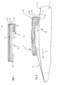
- Adhesive 01 For carrying out the method, a trained in the manner of an adhesive tape Adhesive 01 can be used, as shown schematically in Fig. 1 in cross section is.
- the adhesive 01 has a carrier tape 05, the adhesive 01 mechanical Gives strength and in which tensile forces can be transmitted.
- an adhesive strip 03 is provided on the top of the carrier tape 05.
- Application of a corresponding adhesive on the carrier tape 05 is formed and is protected by a cover strip 06.
- This adhesive zone 08 has at least two Adhesive strips 09, 10, which are separated by a splitting paper 04. Of the Adhesive strip 02 is single-layered and formed without splitting paper 04.
- the two located on the underside of the carrier tape 05 splices 02; 08 can be separated by a gap 07 from each other.
- FIG Fig. 2 The use of the adhesive 01 when carrying out the processes are shown schematically in FIG Fig. 2 shown.
- the adhesive 01 on the web start 11 and the Circumference 12, d. H. a second material layer 12, manually or by using appropriate mechanical gripping elements of the new material roll 13, z. B. paper roll 13 applied.
- the web start 11 or the adhesive 01 of a in the manner of a Paper guide roller trained pressing element (not shown) against the circumference 12th the material roll 13 is pressed.
- the adhesive 01 passes with the adhesive zone 08 in the Area of the circumference 12 of the new roll of material 13, so that by the contact of the Adhesive zone 08 is fixed with the circumference 12 of the web start 11 on the circumference 12.
- the cover strip 06 is removed from the adhesive tape 03. This is the Bonded to the new roll of material 13 ready prepared.
- the adhesive zone 08 along a gap paper 04 between the Adhesive strips 09 and 10 split, so that after the fixation of the adhesive zone 08 at the material web 12, the adhesive 01 by splitting between the adhesives. 9 and 10 is separated.
Landscapes
- Chemical & Material Sciences (AREA)
- Organic Chemistry (AREA)
- Replacement Of Web Rolls (AREA)
- Adhesives Or Adhesive Processes (AREA)
- Standing Axle, Rod, Or Tube Structures Coupled By Welding, Adhesion, Or Deposition (AREA)
- Laminated Bodies (AREA)
- Control Of Metal Rolling (AREA)
- Power-Operated Mechanisms For Wings (AREA)
- Spinning Or Twisting Of Yarns (AREA)
- Folding Of Thin Sheet-Like Materials, Special Discharging Devices, And Others (AREA)
- Adhesive Tapes (AREA)
Abstract
Description
- Fig. 1
- ein zur Klebestellenvorbereitung einer Materialrolle geeignetes Klebemittel im Querschnitt;
- Fig. 2
- eine Bearbeitungsphase während der Klebestellenvorbereitung in schematisch dargestellter seitlicher Ansicht.
- 01
- Klebemittel
- 02
- Klebestreifen, erster
- 03
- Klebestreifen, zweiter
- 04
- Spaltpapier
- 05
- Trägerband
- 06
- Abdeckstreifen (03)
- 07
- Spalt
- 08
- Klebezone, Klebemittel
- 09
- Klebestreifen
- 10
- Klebestreifen
- 11
- Bahnanfang (15)
- 12
- Umfang, Materiallage, zweite (13)
- 13
- Materialrolle, Papierrolle
- 14
- -
- 15
- Materialbahn, Papierbahn
- 16
- Bewegungspfeil
Claims (7)
- Verfahren zur Verbindung eines Bahnanfanges (11) einer ersten Materialbahn (15) einer Materialrolle (13) mit einer anderen Materialbahn einer anderen Materialrolle mittels eines Klebemittels (01), wobei das Klebemittel (01) ein Trägerband (05) aufweist, auf dessen Oberseite mindestens ein Klebestreifen (03) angeordnet ist und auf dessen Unterseite mindestens eine weitere Klebezone (08) ausgebildet ist, wobei die Klebezone (08) mit der zweiten Materiallage (12) der Materialrolle (13) verbunden wird, und wobei das Trägerband (05) mittels eines anderen Klebestreifens (02) auf der Oberseite des Bahnanfanges (11) der ersten Materialbahn (15) verbunden wird, dadurch gekennzeichnet, dass die Klebezone (08) mindestens zwei Klebestreifen (09, 10) aufweist, die durch ein Spaltpapier (04) voneinander getrennt sind und der Klebestreifen (02) und die Klebezone (08) durch einen Spalt (07) voneinander getrennt sind, dass zum Fixieren des Bahnanfanges (11) das Klebemittel (01) mittels eines Andrückelementes gegen den Umfang (12) der Materialrolle (13) gedrückt wird.
- Verfahren nach Anspruch 1, dadurch gekennzeichnet, dass vor Aufbringen des Klebemittels (01) auf den Bahnanfang (11) der ersten Materialbahn (15) dieser Bahnanfang (11) geschnitten wird.
- Verfahren nach Anspruch 2, dadurch gekennzeichnet, dass der Bahnanfang (11) unter Bildung einer exakten Schnittkante parallel oder geneigt zur Rotationsachse der Materialrolle (13) geschnitten wird.
- Verfahren nach Anspruch 1, dadurch gekennzeichnet, dass zuerst das Klebemittel (01) am Bahnanfang (11) der Materialbahn (15) der Materialrolle (13) fixiert wird und anschließend das Klebemittel (01) mit der zweiten Materiallage (12) dieser Materialrolle (13) fixiert wird.
- Verfahren nach Anspruch 1, dadurch gekennzeichnet, dass der Bahnanfang (11) zum Fixieren des Klebemittels (01) am Bahnanfang (11) flächig ausgelegt wird.
- Verfahren nach Anspruch 5, dadurch gekennzeichnet, dass der Bahnanfang (11) auf einem Bearbeitungstisch ausgelegt wird.
- Verfahren nach Anspruch 5, dadurch gekennzeichnet, dass nach Fixierung des Klebemittels (01) der Bahnanfang (11) auf die Materialrolle (13) zurückgespult wird.
Applications Claiming Priority (3)
| Application Number | Priority Date | Filing Date | Title |
|---|---|---|---|
| DE10118362 | 2001-04-12 | ||
| DE10118362A DE10118362B4 (de) | 2001-04-12 | 2001-04-12 | Verfahren zur Verbindung eines Bahnanfanges einer Materialrolle |
| EP02729820A EP1381552B1 (de) | 2001-04-12 | 2002-03-26 | Verfahren zur verbindung eines bahnanfanges |
Related Parent Applications (1)
| Application Number | Title | Priority Date | Filing Date |
|---|---|---|---|
| EP02729820A Division EP1381552B1 (de) | 2001-04-12 | 2002-03-26 | Verfahren zur verbindung eines bahnanfanges |
Publications (3)
| Publication Number | Publication Date |
|---|---|
| EP1524217A2 true EP1524217A2 (de) | 2005-04-20 |
| EP1524217A3 EP1524217A3 (de) | 2005-04-27 |
| EP1524217B1 EP1524217B1 (de) | 2006-06-21 |
Family
ID=7681424
Family Applications (2)
| Application Number | Title | Priority Date | Filing Date |
|---|---|---|---|
| EP05100199A Expired - Lifetime EP1524217B1 (de) | 2001-04-12 | 2002-03-26 | Verfahren zur Verbindung eines Bahnanfanges |
| EP02729820A Revoked EP1381552B1 (de) | 2001-04-12 | 2002-03-26 | Verfahren zur verbindung eines bahnanfanges |
Family Applications After (1)
| Application Number | Title | Priority Date | Filing Date |
|---|---|---|---|
| EP02729820A Revoked EP1381552B1 (de) | 2001-04-12 | 2002-03-26 | Verfahren zur verbindung eines bahnanfanges |
Country Status (7)
| Country | Link |
|---|---|
| US (1) | US6790302B2 (de) |
| EP (2) | EP1524217B1 (de) |
| JP (1) | JP2004521047A (de) |
| AT (2) | ATE330890T1 (de) |
| DE (3) | DE10118362B4 (de) |
| ES (2) | ES2301639T3 (de) |
| WO (1) | WO2002083532A1 (de) |
Families Citing this family (12)
| Publication number | Priority date | Publication date | Assignee | Title |
|---|---|---|---|---|
| US8641591B2 (en) | 2010-08-26 | 2014-02-04 | Pregis Innovative Packaging, Inc. | Center-fed dunnage system |
| EP2433994B1 (de) * | 2010-09-27 | 2013-12-25 | Illinois Tool Works Inc. | Klebeband und Verfahren zu seiner Herstellung |
| WO2012088521A2 (en) | 2010-12-23 | 2012-06-28 | Pregis Innovative Packaging, Inc. | Center-fed dunnage system feed and cutter |
| CA2849084C (en) | 2011-09-20 | 2018-07-03 | Pregis Innovative Packaging, Inc. | Tear-assist apparatus |
| US20140038805A1 (en) * | 2012-08-03 | 2014-02-06 | Pregis Innovative Packaging, Inc. | Dunnage supply daisy chain connector |
| US10166738B2 (en) * | 2017-05-08 | 2019-01-01 | Tesa Se | Flying splice tape with residue-free fastener for woven and nonwoven fibrous materials |
| US10940659B2 (en) | 2017-05-11 | 2021-03-09 | Pregis Innovative Packaging Llc | Strap assembly on stock material units for a dunnage conversion machine |
| US11034121B2 (en) | 2017-05-11 | 2021-06-15 | Pregis Innovative Packaging Llc | Dunnage apparatus carton filler |
| US11020930B2 (en) | 2017-05-11 | 2021-06-01 | Pregis Innovative Packaging Llc | Splice member on stock material units for a dunnage conversion machine |
| US10926506B2 (en) | 2017-05-11 | 2021-02-23 | Pregis Innovative Packaging Llc | Fanfold supply cart |
| US11007746B2 (en) | 2017-05-11 | 2021-05-18 | Pregis Innovative Packaging Llc | Dunnage supply intake |
| WO2022216638A1 (en) | 2021-04-05 | 2022-10-13 | Sandar Industries, Inc | Improved methods and apparatus for separating and spooling a paper web |
Family Cites Families (13)
| Publication number | Priority date | Publication date | Assignee | Title |
|---|---|---|---|---|
| US2149832A (en) * | 1932-04-22 | 1939-03-07 | Donald M Carter | Roll of paper for high speed pasters |
| DE4033900C2 (de) * | 1990-04-03 | 1995-07-27 | Voith Gmbh J M | Splice-Stelle am Bahnanfang eines Wickels zum Verbinden des Bahnanfangs mit dem Bahnende eines anderen Wickels |
| ATE156454T1 (de) * | 1990-04-03 | 1997-08-15 | Voith Gmbh J M | Einrichtung zum aufbringen eines klebebandes auf den bahnanfang eines bahnwickels |
| DE4210329A1 (de) * | 1992-03-30 | 1993-10-07 | Koenig & Bauer Ag | Anordnung zum Verbinden aufeinanderfolgender, zu Rollen gewickelter Papierbahnen |
| DE4339309A1 (de) * | 1993-01-19 | 1994-07-21 | Heidelberger Druckmasch Ag | Bahnverbindungsklebeband für eine neue Bahnrolle |
| CN1064019C (zh) * | 1994-04-26 | 2001-04-04 | 美国3M公司 | 拼接胶带和使用该拼接胶带的拼接方法 |
| DE29621879U1 (de) * | 1996-12-17 | 1997-02-27 | Voith Sulzer Papiermaschinen GmbH, 89522 Heidenheim | Anordnung von Klebeschichten einer Splice-Stelle |
| EP0981487B1 (de) * | 1997-05-16 | 2001-07-11 | Koenig & Bauer Aktiengesellschaft | Verfahren und vorrichtung zum erfassen eines teiles einer äusseren lage einer materialbahn von einer vorratsrolle |
| US6432241B1 (en) * | 1998-03-13 | 2002-08-13 | 3M Innovative Properties Company | Splicing tape, splicing method and assembly comprising the splicing tape |
| DE19830674A1 (de) | 1998-07-09 | 2000-01-13 | Beiersdorf Ag | Klebeband und seine Verwendung |
| DE19830673A1 (de) * | 1998-07-09 | 2000-01-13 | Beiersdorf Ag | Klebeband und seine Verwendung |
| DE19902179B4 (de) * | 1999-01-21 | 2005-04-28 | Tesa Ag | Klebeband und Spliceverfahren |
| US20050103429A1 (en) | 2001-09-19 | 2005-05-19 | Markus Eikmeier | Adhesive tape for automatic replacement of rolls |
-
2001
- 2001-04-12 DE DE10118362A patent/DE10118362B4/de not_active Expired - Fee Related
-
2002
- 2002-03-26 ES ES02729820T patent/ES2301639T3/es not_active Expired - Lifetime
- 2002-03-26 EP EP05100199A patent/EP1524217B1/de not_active Expired - Lifetime
- 2002-03-26 AT AT05100199T patent/ATE330890T1/de not_active IP Right Cessation
- 2002-03-26 US US10/474,040 patent/US6790302B2/en not_active Expired - Fee Related
- 2002-03-26 JP JP2002581299A patent/JP2004521047A/ja active Pending
- 2002-03-26 WO PCT/DE2002/001090 patent/WO2002083532A1/de not_active Ceased
- 2002-03-26 ES ES05100199T patent/ES2264797T3/es not_active Expired - Lifetime
- 2002-03-26 AT AT02729820T patent/ATE391689T1/de not_active IP Right Cessation
- 2002-03-26 EP EP02729820A patent/EP1381552B1/de not_active Revoked
- 2002-03-26 DE DE50207344T patent/DE50207344D1/de not_active Expired - Lifetime
- 2002-03-26 DE DE50212068T patent/DE50212068D1/de not_active Revoked
Also Published As
| Publication number | Publication date |
|---|---|
| ATE391689T1 (de) | 2008-04-15 |
| EP1381552A1 (de) | 2004-01-21 |
| US20040134591A1 (en) | 2004-07-15 |
| EP1524217B1 (de) | 2006-06-21 |
| DE10118362A1 (de) | 2002-10-24 |
| ATE330890T1 (de) | 2006-07-15 |
| WO2002083532B1 (de) | 2002-12-05 |
| EP1381552B1 (de) | 2008-04-09 |
| JP2004521047A (ja) | 2004-07-15 |
| EP1524217A3 (de) | 2005-04-27 |
| ES2301639T3 (es) | 2008-07-01 |
| DE50212068D1 (de) | 2008-05-21 |
| WO2002083532A1 (de) | 2002-10-24 |
| ES2264797T3 (es) | 2007-01-16 |
| DE10118362B4 (de) | 2006-07-27 |
| US6790302B2 (en) | 2004-09-14 |
| DE50207344D1 (de) | 2006-08-03 |
Similar Documents
| Publication | Publication Date | Title |
|---|---|---|
| EP0566880B1 (de) | Anordnung zum Verbinden aufeinanderfolgender, zu Rollen gewickelter Papierbahnen | |
| EP0970904B1 (de) | Klebeband und seine Verwendung | |
| DE4033900C2 (de) | Splice-Stelle am Bahnanfang eines Wickels zum Verbinden des Bahnanfangs mit dem Bahnende eines anderen Wickels | |
| DE3430739C2 (de) | Verfahren zum Schneiden und Ausstanzen sowie Zuführen von Aufklebern verschiedener Formen | |
| EP0746462B1 (de) | Vorrichtung zur übertragung von einseitig selbstklebenden abschnitten von einer bewegten ersten bahn auf eine bewegte zweite bahn | |
| EP0548607B1 (de) | Verfahren und Vorrichtung zum Ablängen einer Materialbahn aus Reifenaufbaumaterial | |
| DE19841609A1 (de) | Haftelement oder -streifen für Fliegenden Rollenwechsel | |
| EP1381552B1 (de) | Verfahren zur verbindung eines bahnanfanges | |
| DE2909276A1 (de) | Selbstklebeband | |
| EP1216034B1 (de) | Verfahren und vorrichtung zum spenden haftklebender laminatabschnitte | |
| EP0790205B1 (de) | Etikettenrolle mit Anhängeelement | |
| DE4026144A1 (de) | Verfahren zum herstellen eines kontinuums von aufklebern | |
| DE10112636B4 (de) | Verfahren und Vorrichtung zur Klebestellenvorbereitung einer Materialrolle | |
| EP2868605B1 (de) | Reißband zum Auftrennen der Papierbahn bei einer Anlage zur Erzeugung von Papier | |
| EP0866010A2 (de) | Vorratspapierbahnrolle | |
| DE19750203A1 (de) | Laminierbarer Markierer und Verfahren zu seiner Herstellung | |
| EP2322461B1 (de) | Wickelhülse mit Haftkleber | |
| EP0800996A2 (de) | Verfahren und Vorrichtung zum Herstellen einer Etikettenrolle | |
| DE2502061C2 (de) | Verfahren und vorrichtung zum verbinden zweier schnittkanten von magnetbaendern | |
| EP1438247B1 (de) | Klebeband für fliegenden rollenwechsel | |
| DE202021105319U1 (de) | Vorrichtung zum Verbinden zweier Etikettenbänder sowie Spleißanordnung, umfassend eine derartige Vorrichtung | |
| EP0989085A1 (de) | Etikettenstreifen | |
| DE9113258U1 (de) | Seitlich abziehbares Klebeband | |
| DE3027487A1 (de) | Verfahren und vorrichtung zur herstellung von selbstklebenden klebebandstreifen |
Legal Events
| Date | Code | Title | Description |
|---|---|---|---|
| PUAI | Public reference made under article 153(3) epc to a published international application that has entered the european phase |
Free format text: ORIGINAL CODE: 0009012 |
|
| PUAL | Search report despatched |
Free format text: ORIGINAL CODE: 0009013 |
|
| AC | Divisional application: reference to earlier application |
Ref document number: 1381552 Country of ref document: EP Kind code of ref document: P |
|
| AK | Designated contracting states |
Kind code of ref document: A2 Designated state(s): AT BE CH CY DE DK ES FI FR GB GR IE IT LI LU MC NL PT SE TR |
|
| AK | Designated contracting states |
Kind code of ref document: A3 Designated state(s): AT BE CH CY DE DK ES FI FR GB GR IE IT LI LU MC NL PT SE TR |
|
| 17P | Request for examination filed |
Effective date: 20050317 |
|
| GRAP | Despatch of communication of intention to grant a patent |
Free format text: ORIGINAL CODE: EPIDOSNIGR1 |
|
| GRAJ | Information related to disapproval of communication of intention to grant by the applicant or resumption of examination proceedings by the epo deleted |
Free format text: ORIGINAL CODE: EPIDOSDIGR1 |
|
| GRAP | Despatch of communication of intention to grant a patent |
Free format text: ORIGINAL CODE: EPIDOSNIGR1 |
|
| AKX | Designation fees paid |
Designated state(s): AT BE CH CY DE DK ES FI FR GB GR IE IT LI LU MC NL PT SE TR |
|
| GRAS | Grant fee paid |
Free format text: ORIGINAL CODE: EPIDOSNIGR3 |
|
| GRAA | (expected) grant |
Free format text: ORIGINAL CODE: 0009210 |
|
| RIN1 | Information on inventor provided before grant (corrected) |
Inventor name: BECK, PETER Inventor name: ROESCH, ANDREAS |
|
| AC | Divisional application: reference to earlier application |
Ref document number: 1381552 Country of ref document: EP Kind code of ref document: P |
|
| AK | Designated contracting states |
Kind code of ref document: B1 Designated state(s): AT BE CH CY DE DK ES FI FR GB GR IE IT LI LU MC NL PT SE TR |
|
| PG25 | Lapsed in a contracting state [announced via postgrant information from national office to epo] |
Ref country code: IT Free format text: LAPSE BECAUSE OF FAILURE TO SUBMIT A TRANSLATION OF THE DESCRIPTION OR TO PAY THE FEE WITHIN THE PRESCRIBED TIME-LIMIT;WARNING: LAPSES OF ITALIAN PATENTS WITH EFFECTIVE DATE BEFORE 2007 MAY HAVE OCCURRED AT ANY TIME BEFORE 2007. THE CORRECT EFFECTIVE DATE MAY BE DIFFERENT FROM THE ONE RECORDED. Effective date: 20060621 Ref country code: NL Free format text: LAPSE BECAUSE OF FAILURE TO SUBMIT A TRANSLATION OF THE DESCRIPTION OR TO PAY THE FEE WITHIN THE PRESCRIBED TIME-LIMIT Effective date: 20060621 Ref country code: IE Free format text: LAPSE BECAUSE OF FAILURE TO SUBMIT A TRANSLATION OF THE DESCRIPTION OR TO PAY THE FEE WITHIN THE PRESCRIBED TIME-LIMIT Effective date: 20060621 |
|
| REG | Reference to a national code |
Ref country code: GB Ref legal event code: FG4D Free format text: NOT ENGLISH |
|
| REG | Reference to a national code |
Ref country code: CH Ref legal event code: EP |
|
| REG | Reference to a national code |
Ref country code: IE Ref legal event code: FG4D Free format text: LANGUAGE OF EP DOCUMENT: GERMAN |
|
| REF | Corresponds to: |
Ref document number: 50207344 Country of ref document: DE Date of ref document: 20060803 Kind code of ref document: P |
|
| REG | Reference to a national code |
Ref country code: SE Ref legal event code: TRGR |
|
| PG25 | Lapsed in a contracting state [announced via postgrant information from national office to epo] |
Ref country code: DK Free format text: LAPSE BECAUSE OF FAILURE TO SUBMIT A TRANSLATION OF THE DESCRIPTION OR TO PAY THE FEE WITHIN THE PRESCRIBED TIME-LIMIT Effective date: 20060921 |
|
| GBT | Gb: translation of ep patent filed (gb section 77(6)(a)/1977) |
Effective date: 20060927 |
|
| PG25 | Lapsed in a contracting state [announced via postgrant information from national office to epo] |
Ref country code: PT Free format text: LAPSE BECAUSE OF FAILURE TO SUBMIT A TRANSLATION OF THE DESCRIPTION OR TO PAY THE FEE WITHIN THE PRESCRIBED TIME-LIMIT Effective date: 20061121 |
|
| NLV1 | Nl: lapsed or annulled due to failure to fulfill the requirements of art. 29p and 29m of the patents act | ||
| ET | Fr: translation filed | ||
| REG | Reference to a national code |
Ref country code: ES Ref legal event code: FG2A Ref document number: 2264797 Country of ref document: ES Kind code of ref document: T3 |
|
| REG | Reference to a national code |
Ref country code: IE Ref legal event code: FD4D |
|
| PLBE | No opposition filed within time limit |
Free format text: ORIGINAL CODE: 0009261 |
|
| STAA | Information on the status of an ep patent application or granted ep patent |
Free format text: STATUS: NO OPPOSITION FILED WITHIN TIME LIMIT |
|
| 26N | No opposition filed |
Effective date: 20070322 |
|
| BERE | Be: lapsed |
Owner name: KOENIG & BAUER A.G. Effective date: 20070331 |
|
| PG25 | Lapsed in a contracting state [announced via postgrant information from national office to epo] |
Ref country code: BE Free format text: LAPSE BECAUSE OF NON-PAYMENT OF DUE FEES Effective date: 20070331 |
|
| PG25 | Lapsed in a contracting state [announced via postgrant information from national office to epo] |
Ref country code: MC Free format text: LAPSE BECAUSE OF NON-PAYMENT OF DUE FEES Effective date: 20070331 |
|
| PG25 | Lapsed in a contracting state [announced via postgrant information from national office to epo] |
Ref country code: GR Free format text: LAPSE BECAUSE OF FAILURE TO SUBMIT A TRANSLATION OF THE DESCRIPTION OR TO PAY THE FEE WITHIN THE PRESCRIBED TIME-LIMIT Effective date: 20060922 |
|
| PGFP | Annual fee paid to national office [announced via postgrant information from national office to epo] |
Ref country code: AT Payment date: 20090324 Year of fee payment: 8 Ref country code: ES Payment date: 20090317 Year of fee payment: 8 |
|
| PGFP | Annual fee paid to national office [announced via postgrant information from national office to epo] |
Ref country code: FI Payment date: 20090325 Year of fee payment: 8 |
|
| PGFP | Annual fee paid to national office [announced via postgrant information from national office to epo] |
Ref country code: CH Payment date: 20090326 Year of fee payment: 8 |
|
| PG25 | Lapsed in a contracting state [announced via postgrant information from national office to epo] |
Ref country code: LU Free format text: LAPSE BECAUSE OF NON-PAYMENT OF DUE FEES Effective date: 20070326 Ref country code: CY Free format text: LAPSE BECAUSE OF FAILURE TO SUBMIT A TRANSLATION OF THE DESCRIPTION OR TO PAY THE FEE WITHIN THE PRESCRIBED TIME-LIMIT Effective date: 20060621 |
|
| PGFP | Annual fee paid to national office [announced via postgrant information from national office to epo] |
Ref country code: IT Payment date: 20090320 Year of fee payment: 8 Ref country code: SE Payment date: 20090324 Year of fee payment: 8 |
|
| PG25 | Lapsed in a contracting state [announced via postgrant information from national office to epo] |
Ref country code: TR Free format text: LAPSE BECAUSE OF FAILURE TO SUBMIT A TRANSLATION OF THE DESCRIPTION OR TO PAY THE FEE WITHIN THE PRESCRIBED TIME-LIMIT Effective date: 20060621 |
|
| REG | Reference to a national code |
Ref country code: CH Ref legal event code: PL |
|
| EUG | Se: european patent has lapsed | ||
| PG25 | Lapsed in a contracting state [announced via postgrant information from national office to epo] |
Ref country code: FI Free format text: LAPSE BECAUSE OF NON-PAYMENT OF DUE FEES Effective date: 20100326 Ref country code: AT Free format text: LAPSE BECAUSE OF NON-PAYMENT OF DUE FEES Effective date: 20100326 |
|
| PG25 | Lapsed in a contracting state [announced via postgrant information from national office to epo] |
Ref country code: CH Free format text: LAPSE BECAUSE OF NON-PAYMENT OF DUE FEES Effective date: 20100331 Ref country code: LI Free format text: LAPSE BECAUSE OF NON-PAYMENT OF DUE FEES Effective date: 20100331 |
|
| PG25 | Lapsed in a contracting state [announced via postgrant information from national office to epo] |
Ref country code: IT Free format text: LAPSE BECAUSE OF NON-PAYMENT OF DUE FEES Effective date: 20100326 |
|
| REG | Reference to a national code |
Ref country code: ES Ref legal event code: FD2A Effective date: 20110415 |
|
| PGFP | Annual fee paid to national office [announced via postgrant information from national office to epo] |
Ref country code: FR Payment date: 20110401 Year of fee payment: 10 |
|
| PG25 | Lapsed in a contracting state [announced via postgrant information from national office to epo] |
Ref country code: ES Free format text: LAPSE BECAUSE OF NON-PAYMENT OF DUE FEES Effective date: 20110404 |
|
| PGFP | Annual fee paid to national office [announced via postgrant information from national office to epo] |
Ref country code: DE Payment date: 20110318 Year of fee payment: 10 Ref country code: GB Payment date: 20110324 Year of fee payment: 10 |
|
| PG25 | Lapsed in a contracting state [announced via postgrant information from national office to epo] |
Ref country code: ES Free format text: LAPSE BECAUSE OF NON-PAYMENT OF DUE FEES Effective date: 20100327 |
|
| PG25 | Lapsed in a contracting state [announced via postgrant information from national office to epo] |
Ref country code: SE Free format text: LAPSE BECAUSE OF NON-PAYMENT OF DUE FEES Effective date: 20100327 |
|
| GBPC | Gb: european patent ceased through non-payment of renewal fee |
Effective date: 20120326 |
|
| REG | Reference to a national code |
Ref country code: FR Ref legal event code: ST Effective date: 20121130 |
|
| PG25 | Lapsed in a contracting state [announced via postgrant information from national office to epo] |
Ref country code: GB Free format text: LAPSE BECAUSE OF NON-PAYMENT OF DUE FEES Effective date: 20120326 Ref country code: FR Free format text: LAPSE BECAUSE OF NON-PAYMENT OF DUE FEES Effective date: 20120402 |
|
| REG | Reference to a national code |
Ref country code: DE Ref legal event code: R119 Ref document number: 50207344 Country of ref document: DE Effective date: 20121002 |
|
| PG25 | Lapsed in a contracting state [announced via postgrant information from national office to epo] |
Ref country code: DE Free format text: LAPSE BECAUSE OF NON-PAYMENT OF DUE FEES Effective date: 20121002 |