EP1523610B1 - Vorrichtung zur veränderung der steuerzeiten einer brennkraftmaschine - Google Patents
Vorrichtung zur veränderung der steuerzeiten einer brennkraftmaschine Download PDFInfo
- Publication number
- EP1523610B1 EP1523610B1 EP03766192A EP03766192A EP1523610B1 EP 1523610 B1 EP1523610 B1 EP 1523610B1 EP 03766192 A EP03766192 A EP 03766192A EP 03766192 A EP03766192 A EP 03766192A EP 1523610 B1 EP1523610 B1 EP 1523610B1
- Authority
- EP
- European Patent Office
- Prior art keywords
- disk
- thrust washer
- camshaft
- turned away
- gearing
- Prior art date
- Legal status (The legal status is an assumption and is not a legal conclusion. Google has not performed a legal analysis and makes no representation as to the accuracy of the status listed.)
- Expired - Fee Related
Links
Images

Classifications
-
- F—MECHANICAL ENGINEERING; LIGHTING; HEATING; WEAPONS; BLASTING
- F01—MACHINES OR ENGINES IN GENERAL; ENGINE PLANTS IN GENERAL; STEAM ENGINES
- F01L—CYCLICALLY OPERATING VALVES FOR MACHINES OR ENGINES
- F01L1/00—Valve-gear or valve arrangements, e.g. lift-valve gear
- F01L1/34—Valve-gear or valve arrangements, e.g. lift-valve gear characterised by the provision of means for changing the timing of the valves without changing the duration of opening and without affecting the magnitude of the valve lift
- F01L1/344—Valve-gear or valve arrangements, e.g. lift-valve gear characterised by the provision of means for changing the timing of the valves without changing the duration of opening and without affecting the magnitude of the valve lift changing the angular relationship between crankshaft and camshaft, e.g. using helicoidal gear
- F01L1/352—Valve-gear or valve arrangements, e.g. lift-valve gear characterised by the provision of means for changing the timing of the valves without changing the duration of opening and without affecting the magnitude of the valve lift changing the angular relationship between crankshaft and camshaft, e.g. using helicoidal gear using bevel or epicyclic gear
-
- F—MECHANICAL ENGINEERING; LIGHTING; HEATING; WEAPONS; BLASTING
- F01—MACHINES OR ENGINES IN GENERAL; ENGINE PLANTS IN GENERAL; STEAM ENGINES
- F01L—CYCLICALLY OPERATING VALVES FOR MACHINES OR ENGINES
- F01L1/00—Valve-gear or valve arrangements, e.g. lift-valve gear
- F01L1/02—Valve drive
- F01L1/022—Chain drive
-
- F—MECHANICAL ENGINEERING; LIGHTING; HEATING; WEAPONS; BLASTING
- F01—MACHINES OR ENGINES IN GENERAL; ENGINE PLANTS IN GENERAL; STEAM ENGINES
- F01L—CYCLICALLY OPERATING VALVES FOR MACHINES OR ENGINES
- F01L1/00—Valve-gear or valve arrangements, e.g. lift-valve gear
- F01L1/34—Valve-gear or valve arrangements, e.g. lift-valve gear characterised by the provision of means for changing the timing of the valves without changing the duration of opening and without affecting the magnitude of the valve lift
- F01L1/344—Valve-gear or valve arrangements, e.g. lift-valve gear characterised by the provision of means for changing the timing of the valves without changing the duration of opening and without affecting the magnitude of the valve lift changing the angular relationship between crankshaft and camshaft, e.g. using helicoidal gear
- F01L1/356—Valve-gear or valve arrangements, e.g. lift-valve gear characterised by the provision of means for changing the timing of the valves without changing the duration of opening and without affecting the magnitude of the valve lift changing the angular relationship between crankshaft and camshaft, e.g. using helicoidal gear making the angular relationship oscillate, e.g. non-homokinetic drive
-
- F—MECHANICAL ENGINEERING; LIGHTING; HEATING; WEAPONS; BLASTING
- F01—MACHINES OR ENGINES IN GENERAL; ENGINE PLANTS IN GENERAL; STEAM ENGINES
- F01L—CYCLICALLY OPERATING VALVES FOR MACHINES OR ENGINES
- F01L1/00—Valve-gear or valve arrangements, e.g. lift-valve gear
- F01L1/46—Component parts, details, or accessories, not provided for in preceding subgroups
-
- F—MECHANICAL ENGINEERING; LIGHTING; HEATING; WEAPONS; BLASTING
- F01—MACHINES OR ENGINES IN GENERAL; ENGINE PLANTS IN GENERAL; STEAM ENGINES
- F01L—CYCLICALLY OPERATING VALVES FOR MACHINES OR ENGINES
- F01L1/00—Valve-gear or valve arrangements, e.g. lift-valve gear
- F01L1/02—Valve drive
- F01L1/024—Belt drive
-
- F—MECHANICAL ENGINEERING; LIGHTING; HEATING; WEAPONS; BLASTING
- F01—MACHINES OR ENGINES IN GENERAL; ENGINE PLANTS IN GENERAL; STEAM ENGINES
- F01L—CYCLICALLY OPERATING VALVES FOR MACHINES OR ENGINES
- F01L1/00—Valve-gear or valve arrangements, e.g. lift-valve gear
- F01L1/02—Valve drive
- F01L1/026—Gear drive
-
- F—MECHANICAL ENGINEERING; LIGHTING; HEATING; WEAPONS; BLASTING
- F01—MACHINES OR ENGINES IN GENERAL; ENGINE PLANTS IN GENERAL; STEAM ENGINES
- F01L—CYCLICALLY OPERATING VALVES FOR MACHINES OR ENGINES
- F01L2301/00—Using particular materials
-
- F—MECHANICAL ENGINEERING; LIGHTING; HEATING; WEAPONS; BLASTING
- F01—MACHINES OR ENGINES IN GENERAL; ENGINE PLANTS IN GENERAL; STEAM ENGINES
- F01L—CYCLICALLY OPERATING VALVES FOR MACHINES OR ENGINES
- F01L2303/00—Manufacturing of components used in valve arrangements
-
- F—MECHANICAL ENGINEERING; LIGHTING; HEATING; WEAPONS; BLASTING
- F16—ENGINEERING ELEMENTS AND UNITS; GENERAL MEASURES FOR PRODUCING AND MAINTAINING EFFECTIVE FUNCTIONING OF MACHINES OR INSTALLATIONS; THERMAL INSULATION IN GENERAL
- F16H—GEARING
- F16H49/00—Other gearings
- F16H49/001—Wave gearings, e.g. harmonic drive transmissions
-
- Y—GENERAL TAGGING OF NEW TECHNOLOGICAL DEVELOPMENTS; GENERAL TAGGING OF CROSS-SECTIONAL TECHNOLOGIES SPANNING OVER SEVERAL SECTIONS OF THE IPC; TECHNICAL SUBJECTS COVERED BY FORMER USPC CROSS-REFERENCE ART COLLECTIONS [XRACs] AND DIGESTS
- Y10—TECHNICAL SUBJECTS COVERED BY FORMER USPC
- Y10T—TECHNICAL SUBJECTS COVERED BY FORMER US CLASSIFICATION
- Y10T74/00—Machine element or mechanism
- Y10T74/19—Gearing
Definitions
- the invention relates to a device for changing the timing of an internal combustion engine with a rotational angle between a drive wheel and a camshaft changing adjusting device, which is designed as Axialexzentergetriebe with a first frontal toothing, rotatably connected to the drive wheel adjusting and with a radial in her outer region of a second frontal toothing having disc whose second frontal toothing is offset via an adjusting device in an adjustment, wherein the frontal teeth are partially engaged and wherein the number of teeth of the frontal teeth differ by at least one tooth.
- a device for changing the timing of an internal combustion engine according to the preamble of claim 1 is known from the EP 1 178 185 A2 , Thereafter, the disc is provided with at least one frontal toothing, which partially meshes with both teeth of a standing with the drive wheel in a rotationally fixed connection first component as well as with a standing with the camshaft in rotationally fixed connection further component.
- the disk itself is rotatably guided via a rolling bearing on a shaft journal of the adjusting device.
- the storage takes a total of one position, which is offset by an angle to the transverse plane of the longitudinal axis of the camshaft. As a result, the disk as a whole is set in a wobbling motion, so that partially teeth of the disk with teeth of the two components are engaged.
- the invention is therefore based on the object to avoid these disadvantages and thus to provide a highly-translated three-shaft transmission, which on the one hand has an extremely compact design with a corresponding weight advantage and which is free of unbalance moments and on which the gear play is minimized.
- this object is achieved in that the disc rotatably connected to the camshaft and is designed as a flexible component in the axial direction of the camshaft, wherein the adjusting device deforms the flexible disc in the axial direction.
- the adjusting device deforms the flexible disc in the axial direction.
- the number of teeth, as usual, between disc and adjusting element differ by at least one tooth.
- the adjusting device may be formed as a thrust washer, which rests against the second toothing of the flexible disc opposite outer surface.
- This thrust washer communicates with a rotor of an electric motor and deforms the disc such that its teeth are partially engaged at one or more locations with the counter teeth.
- the pressure disk can have one or more local elevations on its surface facing the disk.
- the aforementioned surface of the thrust washer is formed overall as extending to the transverse plane of the camshaft inclined plane.
- the course of the surface can also be formed approximately harmonically in another way, for example, by running according to a sinusoidal function.
- the number of sections in which the pressure plate has elevations corresponds to the number of engagement points. Several points are engaged per point of engagement, with the number of bearing teeth increasing with the torque acting between the input and output shafts. If the pressure disk rotates, the raised portions rotate, resulting in a relative adjustment of the disk to the adjusting element.
- the thrust washer may be supported on its surface facing away from the disc on a housing wall of the adjusting device. In this way, it is possible to make the thrust washer thinner or made of a lighter material.
- the thrust washer and / or the rotor may be made of light metal or plastic, for example, or consist of a composite material. As a result, the moment of inertia of the relatively moving components is advantageously minimized.
- the disk-facing surface of the adjustment is preferably formed substantially spherical.
- the disc rotatably fixed to the camshaft can be deformed in a favorable manner around the point of its attachment, the toothing provided on its outer circumference lying flat against the counter-toothing in the partially deformed regions.
- the thrust washer to receive rolling elements, via which it is mounted axially on the disc.
- the thrust washer may for example have concave pockets in which the rolling elements are guided.
- rolling bodies can also be provided on the side of the pressure disk facing the housing wall. Through this axial roller bearing of the pressure plate can be total realize a low-friction drive, which of course also premature wear of the components can be prevented.
- the rolling elements are preferably designed as cylindrical rollers or needles. It is also possible to lead rolling elements in a cage and form with different diameters.
- the disc should be fixed against rotation at its radially inner portion by at least one strained on the camshaft by means of a central screw ring. Between an annular contact surface of the camshaft and this ring, the disc is braced at its radially inner portion, so that there is a frictional connection of the components disc and camshaft.
- the adhesion can be increased by additional diamond or tungsten carbide coated washers. If this non-positive connection is not sufficient for the function, it may instead be provided with a positive connection in which the disc is provided at its radially inner portion with recesses or projections in corresponding recesses and projections of both the ring and the contact surface engage the camshaft.
- both the thrust washer and a cooperating with this rotor should be mounted on the camshaft. It is possible, this storage, which is preferably designed as a needle bearing, provided on the outer circumference of the disc with the camshaft bracing ring.
- FIG. 1 is denoted by 1 an end portion of a camshaft of an internal combustion engine, on which a sprocket designed as a drive wheel 2 is rotatably mounted.
- This drive wheel 2 is driven by a driven gear, not shown, a crankshaft of the internal combustion engine via a chain, also not shown.
- a driven gear not shown
- a crankshaft of the internal combustion engine via a chain, also not shown.
- a toothed belt or gear drive may be provided, in which case a corresponding tooth pitch of the toothed belt adapted drive wheel is provided.
- a housing 4 is braced via fastening screws 3, which consists of an annular housing part 5 and a disk-shaped housing 6.
- the drive wheel 2, the annular housing part 5 and the disk-shaped housing wall 6 together form an inner space 7 of the housing 4.
- the drive wheel 2 has on its side facing the interior 7 a side serving as adjusting 8 section, which is provided with a first front teeth 9.
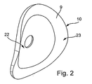
- a disc 10 is arranged, which is deformable in the axial direction of the camshaft.
- the disc 10 has a second frontal toothing 11, which is not in engagement with the first frontal toothing 9 in a state in which it is not deformed.
- the disc 10 is thereby fixed to the end portion 1 of the camshaft that it is clamped between a flange 12 and a ring 13 by means of a central screw 14.
- the collar having a central screw 14 is screwed axially into the end portion 1 of the camshaft.
- the ring 13 also serves to support a rotor 15 which, as in the following FIGS. 3 and 4 shown schematically, cooperates with a stator 16 of an electric motor drive.
- the rotor 15 is formed as an adjusting shaft and connected to a not shown in detail motor shaft.
- the pressure plate 17 is provided at least at one point of the disk 10 facing end face with a survey 18, said survey 18 of the FIG. 1 in the lower half of the sectional view can be removed.
- this survey 18 the disc 10 is deformed so far in the axial direction that their second frontal toothing 11 is partially engaged with the first frontal toothing 9 of the adjusting element.
- the first end toothing 9 is provided with a convex contour.
- two sets of cylindrical rollers 19 and 20 are arranged, wherein a first set of the cylindrical rollers 19 abuts the second frontal toothing 11 facing away from the end face of the disc 10, while the pressure plate 17 by means of the second set of cylindrical rollers 20 on the disc-shaped Housing 6 supported.
- the Rotor 15 mounted together with the pressure plate 17 by means of a needle bearing 21 on an outer circumference of the ring 13.
- the cylindrical rollers 19 may be omitted, with the appropriately trained thrust washer slides on the disc.
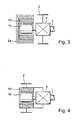
- FIG. 3 is a schematic diagram of a structure of a three-shaft transmission, in which the stator 16 is disposed within a cylinder head 23.
- the stator 16 is thus stationary, and at a current supply preferably of the electric motor, the rotor 15 is due to its own rotational speed, which is different from the rotational speed of the drive wheel 2, a rotation of in FIG. 1 bring shown pressure plate 17.
- FIG. 4 is a stator 16 'disposed within a drive wheel 2' and thus rotates at the speed of the drive wheel 2 'and at half the speed of the crankshaft of the internal combustion engine.
- the energization of the electric motor can be done for example by means of a slip ring or transponder, not shown.
- FIG. 1 how the particular FIG. 1 combined with FIG. 2 can be seen in the inventive device for changing the timing of an internal combustion engine, the adjustment of the timing, ie a rotation of the camshaft (end portion 1 of the camshaft) relative to the drive wheel 2 by means of a Axialexzentergetriebes, which is designed extremely compact and on which an undesirable Vernierungsspiel avoided can be.
- the thrust washer provided with at least one elevation 18 projecting in the axial direction is rotated relative to the drive wheel 2 such that all portions of the frontal toothings 11 of the disk 10 and the toothing 9 of the adjusting element 8 arranged on the drive wheel 2 engage in succession reach.
Landscapes
- Engineering & Computer Science (AREA)
- Mechanical Engineering (AREA)
- General Engineering & Computer Science (AREA)
- Valve Device For Special Equipments (AREA)
Applications Claiming Priority (5)
| Application Number | Priority Date | Filing Date | Title |
|---|---|---|---|
| DE10233698 | 2002-07-24 | ||
| DE10233698 | 2002-07-24 | ||
| US39862402P | 2002-07-25 | 2002-07-25 | |
| US398624P | 2002-07-25 | ||
| PCT/EP2003/007712 WO2004013467A1 (de) | 2002-07-24 | 2003-07-16 | Vorrichtung zur veränderung der steuerzeiten einer brennkraftmaschine |
Publications (2)
| Publication Number | Publication Date |
|---|---|
| EP1523610A1 EP1523610A1 (de) | 2005-04-20 |
| EP1523610B1 true EP1523610B1 (de) | 2009-01-14 |
Family
ID=31496727
Family Applications (1)
| Application Number | Title | Priority Date | Filing Date |
|---|---|---|---|
| EP03766192A Expired - Fee Related EP1523610B1 (de) | 2002-07-24 | 2003-07-16 | Vorrichtung zur veränderung der steuerzeiten einer brennkraftmaschine |
Country Status (7)
| Country | Link |
|---|---|
| US (1) | US7047923B2 (ja) |
| EP (1) | EP1523610B1 (ja) |
| JP (1) | JP4286780B2 (ja) |
| CN (1) | CN1671950A (ja) |
| AU (1) | AU2003246707A1 (ja) |
| DE (1) | DE50311096D1 (ja) |
| WO (1) | WO2004013467A1 (ja) |
Cited By (1)
| Publication number | Priority date | Publication date | Assignee | Title |
|---|---|---|---|---|
| US10060067B2 (en) | 2016-05-10 | 2018-08-28 | Haier Us Appliance Solutions, Inc. | Determining out of balance conditions of a washing machine |
Families Citing this family (24)
| Publication number | Priority date | Publication date | Assignee | Title |
|---|---|---|---|---|
| DE102004005795A1 (de) * | 2004-02-06 | 2005-08-25 | Daimlerchrysler Ag | Vorrichtung zur Winkelverstellung einer Nockenwelle gegenüber einer Kurbelwelle einer Brennkraftmaschine |
| DE102004038681B4 (de) * | 2004-08-10 | 2017-06-01 | Schaeffler Technologies AG & Co. KG | Elektromotorischer Nockenwellenversteller |
| DE102004062068A1 (de) * | 2004-12-23 | 2006-07-06 | Schaeffler Kg | Vorrichtung zur Veränderung der Steuerzeiten einer Brennkraftmaschine |
| DE102004062038B4 (de) * | 2004-12-23 | 2017-09-07 | Schaeffler Technologies AG & Co. KG | Vorrichtung zur Veränderung der Steuerzeiten einer Brennkraftmaschine |
| DE102005018957A1 (de) * | 2005-04-23 | 2006-11-23 | Schaeffler Kg | Vorrichtung zur variablen Einstellung der Steuerzeiten von Gaswechselventilen einer Brennkraftmaschine |
| DE102007046819B4 (de) * | 2007-09-29 | 2016-12-01 | Dr. Ing. H.C. F. Porsche Aktiengesellschaft | Verfahren und Vorrichtung zum Starten eines direkteinspritzenden Verbrennungsmotors sowie Kraftfahrzeug |
| DE102007056550A1 (de) * | 2007-11-23 | 2009-05-28 | Schaeffler Kg | Modular aufgebauter Nockenwellenversteller mit Ketten- oder Riemenrad |
| JP2009185785A (ja) * | 2008-02-08 | 2009-08-20 | Denso Corp | バルブタイミング調整装置 |
| US8418665B2 (en) * | 2008-04-23 | 2013-04-16 | Nittan Valve Co., Ltd. | Variable phase controller for automotive engine |
| DE102009006957A1 (de) * | 2009-01-31 | 2010-08-05 | Sbs Feintechnik Gmbh & Co.Kg | Verstelleinrichtung für Nockenwellen von Verbrennungsmotoren von Fahrzeugen, wie Kraftfahrzeuge, Boote, Schiffe oder dergleichen |
| DE102009049218A1 (de) * | 2009-10-13 | 2011-04-28 | Mahle International Gmbh | Nockenwelle für eine Brennkraftmaschine |
| EP2561189B1 (en) * | 2010-04-23 | 2017-10-25 | Borgwarner Inc. | Concentric camshaft phaser flex plate |
| JP5538053B2 (ja) * | 2010-04-28 | 2014-07-02 | 日立オートモティブシステムズ株式会社 | 内燃機関の可変動弁装置 |
| DE102013215816B3 (de) * | 2013-04-22 | 2014-10-16 | Magna Powertrain Ag & Co. Kg | Nockenwellenversteller |
| WO2015121975A1 (ja) * | 2014-02-14 | 2015-08-20 | アイシン精機株式会社 | 弁開閉時期制御装置 |
| US9664073B2 (en) * | 2014-02-25 | 2017-05-30 | Delphi Technologies, Inc. | Modular electrically actuated camshaft phaser |
| JP6125094B2 (ja) * | 2014-03-11 | 2017-05-10 | 日立オートモティブシステムズ株式会社 | 内燃機関のバルブタイミング制御装置 |
| DE102014209312B4 (de) * | 2014-05-16 | 2020-12-03 | Schaeffler Technologies AG & Co. KG | Nockenwellenverstellanordnung, umfassend eine axiale Sicherung mittels einer Spannhülse |
| JP2017206990A (ja) * | 2016-05-18 | 2017-11-24 | 株式会社ミクニ | 位相変更ユニット及びバルブタイミング変更装置 |
| DE102016220919A1 (de) * | 2016-10-25 | 2018-04-26 | Schaeffler Technologies AG & Co. KG | Verstellgetriebeanordnung für ein Fahrzeug, Fahrzeug mit der Verstellgetriebeanordnung sowie Verfahren zur Montage der Verstellgetriebeanordnung |
| DE102016223474B3 (de) | 2016-11-25 | 2018-03-08 | Schaeffler Technologies AG & Co. KG | Verstellgetriebevorrichtung für eine Welle sowie Fahrzeug mit der Verstellgetriebevorrichtung |
| US10539048B2 (en) * | 2017-09-20 | 2020-01-21 | Borgwarner, Inc. | Hydraulic lock for electrically-actuated camshaft phasers |
| JP6961812B2 (ja) * | 2018-09-20 | 2021-11-05 | 株式会社ハーモニック・ドライブ・システムズ | ユニット型波動歯車装置 |
| KR102565616B1 (ko) * | 2019-09-27 | 2023-08-09 | 가부시키가이샤 하모닉 드라이브 시스템즈 | 편평 파동기어장치 |
Family Cites Families (4)
| Publication number | Priority date | Publication date | Assignee | Title |
|---|---|---|---|---|
| DE2352016A1 (de) * | 1973-10-17 | 1975-04-30 | Vdo Schindling | Getriebe fuer kleine leistungen |
| IT1196675B (it) * | 1984-01-10 | 1988-11-25 | Oscar Cordara | Dispositivo meccanico coassiale per la riduzione della velocita angolare nel moto rotatorio |
| DE10038354C2 (de) * | 2000-08-05 | 2003-03-20 | Atlas Fahrzeugtechnik Gmbh | Steuereinrichtung zum Verstellen des Drehwinkels einer Nockenwelle |
| JP3937164B2 (ja) * | 2002-04-19 | 2007-06-27 | 株式会社デンソー | バルブタイミング調整装置 |
-
2003
- 2003-07-16 AU AU2003246707A patent/AU2003246707A1/en not_active Abandoned
- 2003-07-16 JP JP2004525221A patent/JP4286780B2/ja not_active Expired - Fee Related
- 2003-07-16 EP EP03766192A patent/EP1523610B1/de not_active Expired - Fee Related
- 2003-07-16 CN CNA03817667XA patent/CN1671950A/zh active Pending
- 2003-07-16 DE DE50311096T patent/DE50311096D1/de not_active Expired - Lifetime
- 2003-07-16 WO PCT/EP2003/007712 patent/WO2004013467A1/de active Application Filing
-
2005
- 2005-01-21 US US11/041,036 patent/US7047923B2/en not_active Expired - Lifetime
Cited By (1)
| Publication number | Priority date | Publication date | Assignee | Title |
|---|---|---|---|---|
| US10060067B2 (en) | 2016-05-10 | 2018-08-28 | Haier Us Appliance Solutions, Inc. | Determining out of balance conditions of a washing machine |
Also Published As
| Publication number | Publication date |
|---|---|
| CN1671950A (zh) | 2005-09-21 |
| US20050217621A1 (en) | 2005-10-06 |
| US7047923B2 (en) | 2006-05-23 |
| JP4286780B2 (ja) | 2009-07-01 |
| AU2003246707A1 (en) | 2004-02-23 |
| WO2004013467A1 (de) | 2004-02-12 |
| EP1523610A1 (de) | 2005-04-20 |
| DE50311096D1 (de) | 2009-03-05 |
| JP2005533964A (ja) | 2005-11-10 |
Similar Documents
| Publication | Publication Date | Title |
|---|---|---|
| EP1523610B1 (de) | Vorrichtung zur veränderung der steuerzeiten einer brennkraftmaschine | |
| DE102008032665B4 (de) | Vorrichtung und Verfahren zur Veränderung des Verdichtungsverhältnisses einer Brennkraftmaschine | |
| EP2221510B1 (de) | Planetenrad mit einem eine axiale Nut aufweisenden Lagerbolzen | |
| DE102004038681A1 (de) | Elektromotorischer Nockenwellenversteller | |
| WO2010043193A1 (de) | Antriebswellenanordnung für ein getriebe eines kraftfahrzeuges | |
| EP3322908B1 (de) | Getriebe mit anlaufscheibe zur axialen sicherung von wälzkörpern eines lagers | |
| WO2009127183A1 (de) | Einrichtung zur verstellung der exzentrizität für ein kurbel-cvt-getriebe | |
| DE19815421A1 (de) | Innenzahnradmaschine | |
| EP2616644B1 (de) | Vorrichtung zur phasenverschiebung des drehwinkels eines antriebsrades zu einem abtriebsrad | |
| DE10054798A1 (de) | Elektrisch angetriebene Vorrichtung zur Drehwinkelverstellung einer Welle gegenüber ihrem Antrieb | |
| DE102016205748B3 (de) | Stellgetriebe | |
| DE102008046821B4 (de) | Kurbelwelle für eine Brennkraftmaschine mit varibaler Verdichtung und Brennkraftmaschine mit variabler Verdichtung | |
| EP2834539B1 (de) | Getriebeanordnung eines schienenfahrzeuges | |
| EP3653905B1 (de) | Exzentergetriebe | |
| DE102004058551B4 (de) | Getriebe | |
| DE102004007052A1 (de) | Verstelleinrichtung für eine Welle | |
| EP1831590B1 (de) | Vorrichtung, insbesondere ein planetengetriebe, mit einem ringartigen grundkörper | |
| WO2006058743A1 (de) | Getriebe | |
| WO2019185088A1 (de) | Wellgetriebe | |
| DE102019102264A1 (de) | Wellgetriebe und Verfahren zur Montage eines Nockenwellenverstellers | |
| EP2414703B1 (de) | Taumelradwolfromgetriebe | |
| DE10232247B3 (de) | Exzentergetriebe, insbesondere Rollenexzentergetriebe | |
| DE102004043077B4 (de) | Vorrichtung zum Erzeugen einer umlaufenden Verformung eines elastischen Getrieberinges | |
| DE102010004579A1 (de) | Ventiltrieb einer Brennkraftmaschine | |
| DE202006011877U1 (de) | Untersetzungsgetriebe |
Legal Events
| Date | Code | Title | Description |
|---|---|---|---|
| PUAI | Public reference made under article 153(3) epc to a published international application that has entered the european phase |
Free format text: ORIGINAL CODE: 0009012 |
|
| 17P | Request for examination filed |
Effective date: 20041130 |
|
| AK | Designated contracting states |
Kind code of ref document: A1 Designated state(s): AT BE BG CH CY CZ DE DK EE ES FI FR GB GR HU IE IT LI LU MC NL PT RO SE SI SK TR |
|
| AX | Request for extension of the european patent |
Extension state: AL LT LV MK |
|
| RIN1 | Information on inventor provided before grant (corrected) |
Inventor name: STEIGERWALD, MARTIN Inventor name: HEYWOOD, JONATHAN Inventor name: SCHAEFER, JENS |
|
| DAX | Request for extension of the european patent (deleted) | ||
| RBV | Designated contracting states (corrected) |
Designated state(s): CZ DE FR IT |
|
| RAP1 | Party data changed (applicant data changed or rights of an application transferred) |
Owner name: SCHAEFFLER KG |
|
| GRAP | Despatch of communication of intention to grant a patent |
Free format text: ORIGINAL CODE: EPIDOSNIGR1 |
|
| GRAS | Grant fee paid |
Free format text: ORIGINAL CODE: EPIDOSNIGR3 |
|
| GRAA | (expected) grant |
Free format text: ORIGINAL CODE: 0009210 |
|
| AK | Designated contracting states |
Kind code of ref document: B1 Designated state(s): CZ DE FR IT |
|
| REF | Corresponds to: |
Ref document number: 50311096 Country of ref document: DE Date of ref document: 20090305 Kind code of ref document: P |
|
| PLBE | No opposition filed within time limit |
Free format text: ORIGINAL CODE: 0009261 |
|
| STAA | Information on the status of an ep patent application or granted ep patent |
Free format text: STATUS: NO OPPOSITION FILED WITHIN TIME LIMIT |
|
| 26N | No opposition filed |
Effective date: 20091015 |
|
| REG | Reference to a national code |
Ref country code: DE Ref legal event code: R081 Ref document number: 50311096 Country of ref document: DE Owner name: SCHAEFFLER TECHNOLOGIES AG & CO. KG, DE Free format text: FORMER OWNER: SCHAEFFLER TECHNOLOGIES GMBH & CO. KG, 91074 HERZOGENAURACH, DE Effective date: 20120828 Ref country code: DE Ref legal event code: R081 Ref document number: 50311096 Country of ref document: DE Owner name: SCHAEFFLER TECHNOLOGIES GMBH & CO. KG, DE Free format text: FORMER OWNER: SCHAEFFLER TECHNOLOGIES GMBH & CO. KG, 91074 HERZOGENAURACH, DE Effective date: 20120828 |
|
| REG | Reference to a national code |
Ref country code: DE Ref legal event code: R081 Ref document number: 50311096 Country of ref document: DE Owner name: SCHAEFFLER TECHNOLOGIES AG & CO. KG, DE Free format text: FORMER OWNER: SCHAEFFLER TECHNOLOGIES AG & CO. KG, 91074 HERZOGENAURACH, DE Effective date: 20140218 Ref country code: DE Ref legal event code: R081 Ref document number: 50311096 Country of ref document: DE Owner name: SCHAEFFLER TECHNOLOGIES GMBH & CO. KG, DE Free format text: FORMER OWNER: SCHAEFFLER TECHNOLOGIES AG & CO. KG, 91074 HERZOGENAURACH, DE Effective date: 20140218 |
|
| REG | Reference to a national code |
Ref country code: DE Ref legal event code: R081 Ref document number: 50311096 Country of ref document: DE Owner name: SCHAEFFLER TECHNOLOGIES AG & CO. KG, DE Free format text: FORMER OWNER: SCHAEFFLER TECHNOLOGIES GMBH & CO. KG, 91074 HERZOGENAURACH, DE Effective date: 20150211 |
|
| REG | Reference to a national code |
Ref country code: FR Ref legal event code: PLFP Year of fee payment: 14 |
|
| REG | Reference to a national code |
Ref country code: FR Ref legal event code: PLFP Year of fee payment: 15 |
|
| PGFP | Annual fee paid to national office [announced via postgrant information from national office to epo] |
Ref country code: IT Payment date: 20170720 Year of fee payment: 15 Ref country code: CZ Payment date: 20170713 Year of fee payment: 15 Ref country code: FR Payment date: 20170727 Year of fee payment: 15 |
|
| PGFP | Annual fee paid to national office [announced via postgrant information from national office to epo] |
Ref country code: DE Payment date: 20170929 Year of fee payment: 15 |
|
| REG | Reference to a national code |
Ref country code: DE Ref legal event code: R119 Ref document number: 50311096 Country of ref document: DE |
|
| PG25 | Lapsed in a contracting state [announced via postgrant information from national office to epo] |
Ref country code: DE Free format text: LAPSE BECAUSE OF NON-PAYMENT OF DUE FEES Effective date: 20190201 Ref country code: CZ Free format text: LAPSE BECAUSE OF NON-PAYMENT OF DUE FEES Effective date: 20180716 Ref country code: FR Free format text: LAPSE BECAUSE OF NON-PAYMENT OF DUE FEES Effective date: 20180731 |
|
| PG25 | Lapsed in a contracting state [announced via postgrant information from national office to epo] |
Ref country code: IT Free format text: LAPSE BECAUSE OF NON-PAYMENT OF DUE FEES Effective date: 20180716 |
|
| P01 | Opt-out of the competence of the unified patent court (upc) registered |
Effective date: 20230522 |