EP1523366B1 - Fil-guide avec segment central souple effile - Google Patents
Fil-guide avec segment central souple effile Download PDFInfo
- Publication number
- EP1523366B1 EP1523366B1 EP02750291A EP02750291A EP1523366B1 EP 1523366 B1 EP1523366 B1 EP 1523366B1 EP 02750291 A EP02750291 A EP 02750291A EP 02750291 A EP02750291 A EP 02750291A EP 1523366 B1 EP1523366 B1 EP 1523366B1
- Authority
- EP
- European Patent Office
- Prior art keywords
- guidewire
- transverse dimension
- core segment
- flexible core
- flexible
- Prior art date
- Legal status (The legal status is an assumption and is not a legal conclusion. Google has not performed a legal analysis and makes no representation as to the accuracy of the status listed.)
- Expired - Lifetime
Links
- 230000007704 transition Effects 0.000 claims description 5
- 238000000034 method Methods 0.000 description 14
- 239000000463 material Substances 0.000 description 9
- 238000000576 coating method Methods 0.000 description 4
- 238000007493 shaping process Methods 0.000 description 4
- 208000012287 Prolapse Diseases 0.000 description 3
- 229910045601 alloy Inorganic materials 0.000 description 3
- 239000000956 alloy Substances 0.000 description 3
- 210000003484 anatomy Anatomy 0.000 description 3
- 210000004204 blood vessel Anatomy 0.000 description 3
- 239000011248 coating agent Substances 0.000 description 3
- 229910000679 solder Inorganic materials 0.000 description 3
- KDLHZDBZIXYQEI-UHFFFAOYSA-N Palladium Chemical compound [Pd] KDLHZDBZIXYQEI-UHFFFAOYSA-N 0.000 description 2
- 238000002399 angioplasty Methods 0.000 description 2
- 238000005219 brazing Methods 0.000 description 2
- 238000010276 construction Methods 0.000 description 2
- 230000007423 decrease Effects 0.000 description 2
- 230000003247 decreasing effect Effects 0.000 description 2
- 229920000295 expanded polytetrafluoroethylene Polymers 0.000 description 2
- BASFCYQUMIYNBI-UHFFFAOYSA-N platinum Chemical compound [Pt] BASFCYQUMIYNBI-UHFFFAOYSA-N 0.000 description 2
- -1 polyethylene Polymers 0.000 description 2
- 229920001343 polytetrafluoroethylene Polymers 0.000 description 2
- 239000004810 polytetrafluoroethylene Substances 0.000 description 2
- 238000005476 soldering Methods 0.000 description 2
- 239000010935 stainless steel Substances 0.000 description 2
- 229910001220 stainless steel Inorganic materials 0.000 description 2
- 238000003466 welding Methods 0.000 description 2
- 241000405070 Percophidae Species 0.000 description 1
- 239000004698 Polyethylene Substances 0.000 description 1
- 239000004642 Polyimide Substances 0.000 description 1
- 229920006362 Teflon® Polymers 0.000 description 1
- 239000000853 adhesive Substances 0.000 description 1
- 238000004026 adhesive bonding Methods 0.000 description 1
- 230000001070 adhesive effect Effects 0.000 description 1
- 210000001367 artery Anatomy 0.000 description 1
- 210000002302 brachial artery Anatomy 0.000 description 1
- 210000004351 coronary vessel Anatomy 0.000 description 1
- 210000001105 femoral artery Anatomy 0.000 description 1
- 229920002313 fluoropolymer Polymers 0.000 description 1
- 239000004811 fluoropolymer Substances 0.000 description 1
- 238000005242 forging Methods 0.000 description 1
- PCHJSUWPFVWCPO-UHFFFAOYSA-N gold Chemical compound [Au] PCHJSUWPFVWCPO-UHFFFAOYSA-N 0.000 description 1
- 229910052737 gold Inorganic materials 0.000 description 1
- 239000010931 gold Substances 0.000 description 1
- 238000013152 interventional procedure Methods 0.000 description 1
- 238000012986 modification Methods 0.000 description 1
- 230000004048 modification Effects 0.000 description 1
- 229910001000 nickel titanium Inorganic materials 0.000 description 1
- 229910052763 palladium Inorganic materials 0.000 description 1
- 230000002093 peripheral effect Effects 0.000 description 1
- 239000004033 plastic Substances 0.000 description 1
- 229920003023 plastic Polymers 0.000 description 1
- 229910052697 platinum Inorganic materials 0.000 description 1
- 229920000573 polyethylene Polymers 0.000 description 1
- 229920001721 polyimide Polymers 0.000 description 1
- 229920000642 polymer Polymers 0.000 description 1
- 229920001296 polysiloxane Polymers 0.000 description 1
- 229920002635 polyurethane Polymers 0.000 description 1
- 239000004814 polyurethane Substances 0.000 description 1
- 238000005096 rolling process Methods 0.000 description 1
- 230000002792 vascular Effects 0.000 description 1
Images
Classifications
-
- A—HUMAN NECESSITIES
- A61—MEDICAL OR VETERINARY SCIENCE; HYGIENE
- A61M—DEVICES FOR INTRODUCING MEDIA INTO, OR ONTO, THE BODY; DEVICES FOR TRANSDUCING BODY MEDIA OR FOR TAKING MEDIA FROM THE BODY; DEVICES FOR PRODUCING OR ENDING SLEEP OR STUPOR
- A61M25/00—Catheters; Hollow probes
- A61M25/01—Introducing, guiding, advancing, emplacing or holding catheters
- A61M25/09—Guide wires
- A61M2025/09058—Basic structures of guide wires
- A61M2025/09083—Basic structures of guide wires having a coil around a core
-
- A—HUMAN NECESSITIES
- A61—MEDICAL OR VETERINARY SCIENCE; HYGIENE
- A61M—DEVICES FOR INTRODUCING MEDIA INTO, OR ONTO, THE BODY; DEVICES FOR TRANSDUCING BODY MEDIA OR FOR TAKING MEDIA FROM THE BODY; DEVICES FOR PRODUCING OR ENDING SLEEP OR STUPOR
- A61M25/00—Catheters; Hollow probes
- A61M25/01—Introducing, guiding, advancing, emplacing or holding catheters
- A61M25/09—Guide wires
- A61M2025/09175—Guide wires having specific characteristics at the distal tip
Definitions
- This invention relates to the field of guidewires for advancing intraluminal devices such as stent delivery catheters, balloon dilatation catheters, atherectomy catheters and the like within body lumens.
- a guiding catheter having a pre-formed distal tip is percutaneously, introduced into a patient's peripheral artery, e.g. femoral or brachial artery, by means of a conventional Seldinger technique and advanced therein until the distale tip of the guiding catheter is seated in the ostium of a desired coronary artery.
- a guidewire is first advanced by itself through the guiding catheter until the distal tip of the guidewire extends beyond the arterial location where the procedure is to be performed. Then a rapid exchange type catheter, such as described in U.S. Patent No.
- 5,061,395 (Yock ) is mounted onto the proximal portion of the guidewire which extends out of the proximal end of the guiding catheter which is outside of the patient.
- the catheter is advanced over the guidewire, while the position of the guidewire is fixed, until the operative element on the rapid exchange type catheter is disposed within the arterial location where the procedure is to be performed.
- the rapid exchange type catheter may be withdrawn from the patient over the guidewire or the guidewire repositioned within the coronary anatomy for an additional procedure.
- a guidewire may also be used in conjunction with the delivery of an intracoronary stent.
- One method and system involves disposing a compressed or otherwise small diameter stent about an expandable member such as a balloon on the distal end of a catheter, advancing the catheter through the patient's vascular system over a guidewire until the stent is in the desired location within a blood vessel.
- the expendable member on the catheter may then be expanded to expand the stent within the blood vessel.
- the dilated expandable member is then contracted and the catheter withdrawn, leaving the expanded stent within the blood vessel, holding the passageway thereof open. This latter method and system can be used concurrently with balloon angioplasty or subsequent thereto.
- a flexible body member such as a helical coil or a tubular body of polymeric material, is typically disposed about and secured to at least part of the distal portion of the core member.
- a flexible core segment which may be the distal extremity of the core member or a separate shapeable ribbon which is secured to the distal extremity of the core member extends through the flexible body and is secured to the distal end of the flexible body by soldering, brazing or welding, or an adhesive in the case of polymeric flexible bodies which forms a rounded distal tip.
- the leading tip is highly flexible and will not damage or perforate the vessel and the portion behind the distal tip is increasingly stiff which better supports a balloon catheter or similar device.
- the flexible core segment or ribbon of a typical guidewire is a small diameter wire which has been flattened to a relatively constant transverse profile. Flattening of the flexible core segment facilitates the shapability of the member.
- a flexible core segment having a constant transverse profile or flexibility can be subject to prolapse during use. Prolapse occurs when the flexible core segment gets bent back on itself in a constrained lumen and is difficult to straighten out with proximal manipulation.
- a guidewire for use in guiding a catheter which has a tip construction that includes a core wire within a helical coil.
- the core wire has a distal tip segment that is tapered and is further impressed with a pair of opposed flattened surfaces extending along the taper. The surfaces lie at an angle to each other and define a progressively flattened tip having increased width in a distal direction to define a duckbill configuration.
- the tip construction is said to provide improved column strength at the tip to resist guidewire prolapse while providing adequate torsional and flexibility characteristics.
- the present invention is directed to a guidewire having an elongate core member with a proximal core section and a distal core section, and a flexible body disposed about and secured to at least a portion of the distal core section.
- the guidewire has an elongated, preferably shapeable flexible core segment which is secured to or which is formed as part of the distal core section and which is secured to the distal end of the flexible body disposed about the distal core section.
- the distal core section may have one or more tapered sections proximal to the flexible core segment which have distally decreasing tapers with substantially round transverse cross sections.
- the tapered, preferably shapeable flexible core segment has a double reverse taper, i.e. a first transverse dimension which distally tapers over a substantival length thereof from a first value to a second smaller value and a second transverse dimension which distally tapers over essentially the same length of the flexible core segment from a first value to a second larger value, i.e. flares outwardly.
- the length of the tapered flexible core segment is about 1 to about 12 cm, preferably about 2 to about 10 cm. At least 50%, preferably at least 75% of the length of the tapered flexible core segment is tapered as described above.
- the distal most portion of the flexible core segment i.e. up to about 15 mm
- the flexible core segment has two pairs of opposing faces which are essentially the mirror image of each other. In one of the pairs the opposing faces converge toward each other while in the other pair the opposing faces diverge from each other.
- the flexible core segment may be formed integrally or out of the distal extremity of the distal core section or may be formed as a distinct structural component or shaping ribbon which needs to be mounted in a suitable manner to the distal core section, e.g. by welding, brazing, soldering, adhesive bonding, mechanical connections and other known mounting processes.
- the flexible core segment may by formed from round or flattened wire and may be coined or rolled or otherwise plastically deformed, e.g. cold forged, to a desired shape and sectional profile. When the flexible core segment is a separate member from the core member, it may be formed before or after it is secured to the core member.
- the flexible body member is disposed about the flexible core segment, preferably along its entire length and may take the form of a helical coil, polymer jacket, or the like.
- the distal end of the flexible body member is secured to the distal end of the flexible core segment and an intermediate portion of the flexible body member is preferably secured to the distal core section proximal to the tapered flexible core segment
- the double taper of the flexible core segments on the distal parts of the guidewire reduces the likelihood of prolapsing or kinking of the guidewire's distal extremity during procedures and may be used to provide a controlled longitudinal variation and transition in flexibility of the core segment to the distal tip of the guidewire.
- a flexible body member such as a helical coil or a tubular plastic member, having a proximal end and a distal end is typically disposed about and secured to the distal section of the elongate core member.
- the taper geometry of the flexible segment may be modeled mathematically. Specific taper or face contours may be selected in keeping with the principles of the invention to achieve optimum performance for specific usage requirements.
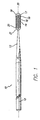
- FIG. 1 is an elevational view of an embodiment of a guidewire 10 which embodies features of the invention, and which includes an elongated core member 11 with a proximal core section 12, a distal core section 13, and a flexible body member or coil 14 which is disposed about and fixed to the distal core section 13.
- the distal core section 13 has a tapered core segment 15 and a flexible core segment 16 which is distally contiguous to the tapered core segment 15 and a distal end 17 which is secured to the distal end 18 of the coil 14 by a rounded body of solder or weld 19.
- the proximal end 20 of the coil 14 is similarly bonded or secured to the distal core section 13 by a body of solder 21.
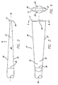
- the flexible core segment 16 which is shown in more detail in Figs. 2-5 , has a first pair of opposed faces 22 and 23 which taper distally from a first transverse dimension 24 to a larger second transverse dimension 25 and a second pair of opposed faces 26 and 27 which taper distally from a first transverse dimension 28 to a smaller transverse dimension 29.
- the first transverse dimensions 24 and 28 of the first and second pairs of opposed faces respectively may have same value or different values.
- flexible core segment 16 tapers to become progressively thinner in one transverse direction and wider in a second transverse direction as the distal end 17 is approached. This results in a smooth decrease in stiffness in one direction but a smooth increase in stiffness in a second direction perpendicular to the first direction.
- each of the tapered faces 22,23,26,27 is shown as having a longitudinal contour that is substantially straight
- the second pair of opposed tapered faces 26,27 have a curved longitudinal contour as may also at least one of the first pair of opposed tapered faces 22,23.
- the side face 22 is shown generally as a mirror image of the side face 23 about the longitudinal axis 30 and the top face 26 is shown generally as a mirror image of the bottom face 27 about the axis 30.
- the opposed faces need not be symmetrical.
- the flexible core segment 16 is shown as being an integral part of the distal core section 13.
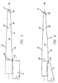
- the flexible core segment 16 is shown as a separate shaping member 31 which has been secured to the distal end of the core member 11 by solder or weldment 32.
- the opposing pairs of faces are the same as that shown in Figs. 2-4 and are provided with the same reference numbers.
- the shaping member 31 is shaped before being secured to the core member 11, whereas, in Fig. 6 the shaping member 31 and the distal tip of the core member 11 has been shaped after being joined together.
- the flexible segment 16 has a length typically ranging about 1 to about 12 cm, preferably about 2 to about 10 cm, although longer segments may be used. At least 50% and preferably at least 75% of the length of the flexible segment 16 is tapered.
- the form of taper of the flexible segment 16 provides a controlled longitudinal variation and transition in flexibility of the distal core section.
- the first transverse or thickness dimension of the taper at a proximal portion of the flexible segment 16 is about 0.025mm to about 0.09mm (0.001-0.0035 inch), preferably about 0.04mm to about 0.06mm (0.0015-0.0025 inch) which tapers to about 0.01 mm to about 0.06mm (0.0005-0.0025 inch), preferably about 0.02mm to about 0.04mm (0.0007-0.0015 inch) at the distal portion.
- the second transverse dimension or width, perpendicular to the first transverse dimension, of the taper at a proximal portion of the flexible segment 16 is about 0.025mm to about 0.09mm (0.001-0.0035 inch), preferably about 0.04mm to about 0.06mm (0.0015-0.0025 inch) which flares to about 0.05mm to about 0.2mm (0.002-0.008 inch), preferably about 0.08mm to about 0.15mm (0.003-0.006 inch).
- the multiple tapers or faces of the flexible core segment 16 are preferably formed by impact forging or rolling a wire or ribbon of suitable dimensions, but other methods may be employed.
- the thickness of the flexible core segment 16 decreases distally as measured between faces 22 and 23, while the width of the flexible segment 16 increases distally as measured between side faces 26 and 27.
- the cross section of the flexible core segment may be generally rectangular in all or in a portion of its length. While not shown, a transition may be provided which tapers from the round transverse cross-section of the proximal portion of the flexible tapered section 16 to the rectangular cross-section of the tapered portion; so as to create a smooth transition at the proximal end of the flexible segment 16.
- the flexible core segment may vary in length from about 0.25 cm to about 10 cm, although both shorter and longer segments may be desirable in some procedures.
- the width and thickness at each cross sectional portion may be varied to provide the desired stiffness along the distal portion of the guidewire.
- the distal section 13 may also have more than one tapered segment 15 which have typical distally decreasing tapers with substantially round transverse cross sections, such as describes, in U.S. Patent Application Ser. No. 081868,764, filed June 4, 1997 (Cornish, et al. ) entitled STEERABLE GUIDEWIRE WITH ENHANCED DISTAL SUPPORT.
- the core member 11 may be formed of stainless steel, NiTi alloys or combinations thereof such as described in U.S. Patent No. 5,341,818 (Abrams et al ). Other materials such as the high ————————————————————— strength alloys described in U.S. Patent No. 5,636,641 (Fariabi ), entitled HIGH STRENGTH MEMBER FOR INTRACORPOREAL USE, ____________ __________ may also be used.
- the core member 11 may be optionally coated with a lubricious coating such as a fluoropolymer, e.g.
- TEFLON ® available from DuPont, which extends at least the length of the proximal core section 12.
- the distal section 13 is also provided with a lubricous coating, such as a MICROGLIDE TM coating (a silicone material). Hydrophilic coatings may also be employed.
- the overall length and diameter of guidewire 10 may be varied to suit the particular procedures in which it is to be used and the materials from which it is constructed.
- the length of the guidewire 10 generally ranges from about 65 cm to about 320 cm, more typically ranging from about 160 cm to about 200 cm.
- Commercially available guidewires for coronary anatomy typically have lengths of about 175 cm or about 190 cm for the coronary anatomy.
- Guidewire diameters generally range from about 0.2mm to about 0.9mm (0.008 to 0.035 inch), more typically ranging from about 0.25mm to about 0.55mm (0.01 to 0.018 inch).
- guidewires for coronary use are typically about 0.25, 0.3 and 0.036mm (0.01, 0.012 and 0.014 inch) in diameter.
- the wire from which the coil 14 is made generally has a transverse diameter of about 0.025mm to about 0.1mm (0.001-0.004 inch), preferably about 0.05mm to about 0.008mm (0.002-0.003 inch). Multiple turns of the distal portion of — coil 14 may be expanded to provide additional flexibility.
- the helical coil 14 may have a diameter or transverse dimension that is about the same as the proximal core section 12.
- the coil 14 may have a length of about 2 to about 40 cm or more, preferably about 2 to about 10 cm in length.
- the coil 14 may at least in part be formed of a suitable radiopaque material such as platinum, palladium or alloys thereof or formed of other material such as stainless steel and coated with a radiopaque material such as gold.
- the coil 14 may be replaced with a flexible body member formed of a polymeric material such as polyimide, polyethylene, polyurethane, polytetrafluoroethylene (PTFE), expanded polytetrafluoroethylene (ePTFE) and other similar materials.
- a polymeric material such as polyimide, polyethylene, polyurethane, polytetrafluoroethylene (PTFE), expanded polytetrafluoroethylene (ePTFE) and other similar materials.
Landscapes
- Health & Medical Sciences (AREA)
- Life Sciences & Earth Sciences (AREA)
- Biophysics (AREA)
- Pulmonology (AREA)
- Engineering & Computer Science (AREA)
- Anesthesiology (AREA)
- Biomedical Technology (AREA)
- Heart & Thoracic Surgery (AREA)
- Hematology (AREA)
- Animal Behavior & Ethology (AREA)
- General Health & Medical Sciences (AREA)
- Public Health (AREA)
- Veterinary Medicine (AREA)
- Media Introduction/Drainage Providing Device (AREA)
Claims (19)
- Fil-guide (10) pour faire avancer des dispositifs intracorporels à un emplacement souhaité dans le corps d'un patient, comprenant:a. un élément d'âme oblong (11) avec une section d'âme proximale (12) et une section d'âme distale (13) avec un segment d'âme flexible oblong (16) qui a une première dimension transversale diminuant distalement d'une première valeur (28) à une deuxième valeur plus petite (29) et qui a une deuxième dimension transversale diminuant distalement d'une première valeur (24) vers une deuxième valeur plus grande (25);b. le segment d'âme flexible oblong (16) comprend une première paire de faces diminuées opposées (22, 23) qui définissent la première dimension transversale, et une deuxième paire de faces diminuées opposées (26, 27) qui définissent la deuxième dimension transversale (24), la deuxième paire de faces diminuées opposées (26, 27) ayant un contour longitudinal qui est courbé; etc. un corps flexible (14) disposé autour et fixé à au moins une portion de la section d'âme distale (13).
- Fil-guide (10) selon la revendication 1, dans lequel le segment d'âme flexible oblong (16) est un élément séparé de l'élément d'âme (11), et qui possède une extrémité distale (17) fixée à l'extrémité distale (18) du corps flexible (14) disposé autour de la section d'âme distale (13) et une extrémité proximale fixée (32) à l'élément d'âme (11).
- Fil-guide (10) selon la revendication 1, dans lequel au moins une de la première paire de faces opposées (22, 23) possède un contour longitudinal qui est sensiblement rectiligne.
- Fil-guide (10) selon la revendication 1, dans lequel au moins une de la première paire de faces opposées (22, 23) possède un contour longitudinal qui est courbé.
- Fil-guide (10) selon la revendication 1, dans lequel la première paire de faces opposées (22, 23) ont une dimension transversale plus grande qu'une dimension transversale correspondante de la deuxième paire de faces opposées (26, 27) sur une longueur substantielle du segment d'âme flexible (16).
- Fil-guide (10) selon la revendication 1, dans lequel la première paire de faces opposées (22, 23) est sensiblement normale à la deuxième paire de faces opposées (26, 27).
- Fil-guide (10) selon la revendication 1, dans lequel le segment d'âme flexible oblong (16) a une longueur d'environ 1 à environ 12 cm.
- Fil-guide (10) selon la revendication 1, dans lequel le segment d'âme flexible oblong (16) a une longueur d'environ 2 à environ 10 cm.
- Fil-guide (10) selon la revendication 1, dans lequel au moins 50% de la longueur du segment d'âme flexible (16) sont diminués.
- Fil-guide (10) selon la revendication 1, dans lequel au moins 75% de la longueur du segment d'âme flexible (16) sont diminués.
- Fil-guide (10) selon la revendication 1, dans lequel la diminution du segment d'âme flexible (16) est configurée pour permettre une variation longitudinale contrôlée et une transition en flexibilité.
- Fil-guide (10) selon la revendication 1, dans lequel la première dimension transversale de la diminution à la portion proximale du segment d'âme flexible (16) est d'environ 0,025 mm à environ à 0,09 mm (0,001-0,0035 pouce).
- Fil-guide (10) selon la revendication 1, dans lequel la première dimension transversale de la diminution à la portion proximale du segment d'âme flexible (16) est d'environ 0,04 mm à environ 0,06 mm (0,0015-0,0025 pouce).
- Fil-guide (10) selon la revendication 12, dans lequel la première dimension transversale diminue à environ 0,01 mm jusqu'à environ 0,06 mm (0,0005-0,0025 pouce).
- Fil-guide (10) selon la revendication 14, dans lequel la première dimension transversale diminue à environ 0,02 mm jusqu'à environ 0,04 mm (0,0007-0,015 pouce).
- Fil-guide (10) selon la revendication 1, dans lequel la deuxième dimension transversale de la diminution, perpendiculaire à la première dimension transversale, à une portion proximale du segment d'âme flexible (16) est d'environ 0,025 mm à environ 0,09 mm (0,001-0,0035 pouce).
- Fil-guide (10) selon la revendication 1, dans lequel la deuxième dimension transversale de la diminution, perpendiculaire à la première dimension transversale, à une portion proximale du segment d'âme flexible (16) est d'environ 0,04 mm à environ 0,006 mm (0,0015-0,0025 pouce).
- Fil-guide (10) selon la revendication 17, dans lequel la deuxième dimension transversale du segment d'âme flexible (16) s'élargit à environ 0,05 mm jusqu'à environ 0,2 mm (0,002-0,008 pouce).
- Fil-guide (10) selon la revendication 17, dans lequel la deuxième dimension transversale du segment d'âme flexible (16) s'élargit à environ 0,08mm jusqu'à environ 0,15 mm (0,003-0,006 pouce).
Applications Claiming Priority (1)
| Application Number | Priority Date | Filing Date | Title |
|---|---|---|---|
| PCT/US2002/023544 WO2004009170A1 (fr) | 2002-07-23 | 2002-07-23 | Fil-guide avec segment central souple effile |
Publications (2)
| Publication Number | Publication Date |
|---|---|
| EP1523366A1 EP1523366A1 (fr) | 2005-04-20 |
| EP1523366B1 true EP1523366B1 (fr) | 2012-09-05 |
Family
ID=30769032
Family Applications (1)
| Application Number | Title | Priority Date | Filing Date |
|---|---|---|---|
| EP02750291A Expired - Lifetime EP1523366B1 (fr) | 2002-07-23 | 2002-07-23 | Fil-guide avec segment central souple effile |
Country Status (5)
| Country | Link |
|---|---|
| EP (1) | EP1523366B1 (fr) |
| JP (1) | JP2005533553A (fr) |
| AU (1) | AU2002319688A1 (fr) |
| ES (1) | ES2390450T3 (fr) |
| WO (1) | WO2004009170A1 (fr) |
Families Citing this family (2)
| Publication number | Priority date | Publication date | Assignee | Title |
|---|---|---|---|---|
| DE202005007570U1 (de) * | 2005-02-22 | 2005-09-08 | Restate Patent Ag | Führungsdraht |
| JP2012200291A (ja) * | 2011-03-23 | 2012-10-22 | Asahi Intecc Co Ltd | ガイドワイヤ |
Family Cites Families (11)
| Publication number | Priority date | Publication date | Assignee | Title |
|---|---|---|---|---|
| US4003369A (en) * | 1975-04-22 | 1977-01-18 | Medrad, Inc. | Angiographic guidewire with safety core wire |
| US4538622A (en) | 1983-11-10 | 1985-09-03 | Advanced Cardiovascular Systems, Inc. | Guide wire for catheters |
| US4748986A (en) | 1985-11-26 | 1988-06-07 | Advanced Cardiovascular Systems, Inc. | Floppy guide wire with opaque tip |
| US5061395A (en) | 1990-01-04 | 1991-10-29 | Ques Industries, Inc. | Hard surface cleaning composition |
| US5135503A (en) | 1990-05-16 | 1992-08-04 | Advanced Cardiovascular Systems, Inc. | Shaping ribbon for guiding members |
| US5345945A (en) | 1990-08-29 | 1994-09-13 | Baxter International Inc. | Dual coil guidewire with radiopaque distal tip |
| EP0495299A1 (fr) | 1990-12-03 | 1992-07-22 | C.R. Bard, Inc. | Construction d'un embout de fil de guidage |
| US5341818A (en) | 1992-12-22 | 1994-08-30 | Advanced Cardiovascular Systems, Inc. | Guidewire with superelastic distal portion |
| US5636641A (en) | 1994-07-25 | 1997-06-10 | Advanced Cardiovascular Systems, Inc. | High strength member for intracorporeal use |
| EP0755693A1 (fr) * | 1995-07-18 | 1997-01-29 | Schneider (Europe) Ag | Fil de guidage de cathéter |
| US6464650B2 (en) * | 1998-12-31 | 2002-10-15 | Advanced Cardiovascular Systems, Inc. | Guidewire with smoothly tapered segment |
-
2002
- 2002-07-23 WO PCT/US2002/023544 patent/WO2004009170A1/fr active Application Filing
- 2002-07-23 JP JP2004522928A patent/JP2005533553A/ja active Pending
- 2002-07-23 EP EP02750291A patent/EP1523366B1/fr not_active Expired - Lifetime
- 2002-07-23 ES ES02750291T patent/ES2390450T3/es not_active Expired - Lifetime
- 2002-07-23 AU AU2002319688A patent/AU2002319688A1/en not_active Abandoned
Also Published As
| Publication number | Publication date |
|---|---|
| WO2004009170A1 (fr) | 2004-01-29 |
| ES2390450T3 (es) | 2012-11-13 |
| EP1523366A1 (fr) | 2005-04-20 |
| AU2002319688A1 (en) | 2004-02-09 |
| JP2005533553A (ja) | 2005-11-10 |
Similar Documents
| Publication | Publication Date | Title |
|---|---|---|
| US6491648B1 (en) | Guidewire with tapered flexible core segment | |
| US8708933B2 (en) | Guidewire having linear change in stiffness | |
| EP1388350B1 (fr) | Fil de guidage | |
| US6132389A (en) | Proximally tapered guidewire tip coil | |
| EP1135185B1 (fr) | Fil de guidage dont la rigidite presente une modification lineaire | |
| US20120041342A1 (en) | High durability coronary guide wire | |
| US6761696B1 (en) | Guide wire with a non-rectangular shaping member | |
| US20210322730A1 (en) | Guidewire having bonded proximal and distal segments | |
| US6740050B2 (en) | Intracorporeal member with improved transition section | |
| US7083577B2 (en) | Guide wire | |
| JP5473677B2 (ja) | ガイドワイヤ | |
| EP1523366B1 (fr) | Fil-guide avec segment central souple effile | |
| US6638267B1 (en) | Guidewire with hypotube and internal insert | |
| JP4375951B2 (ja) | ガイドワイヤ | |
| JP4405252B2 (ja) | 医療用ワイヤ | |
| JP2004065796A (ja) | ガイドワイヤ | |
| JP3962652B2 (ja) | ガイドワイヤ | |
| JP2003334253A (ja) | ガイドワイヤー | |
| JP4116944B2 (ja) | ガイドワイヤ | |
| JP2004065794A (ja) | ガイドワイヤ | |
| JP2008110266A (ja) | ガイドワイヤ | |
| JP2004073252A (ja) | ガイドワイヤ | |
| JP2004065795A (ja) | ガイドワイヤ |
Legal Events
| Date | Code | Title | Description |
|---|---|---|---|
| PUAI | Public reference made under article 153(3) epc to a published international application that has entered the european phase |
Free format text: ORIGINAL CODE: 0009012 |
|
| 17P | Request for examination filed |
Effective date: 20050207 |
|
| AK | Designated contracting states |
Kind code of ref document: A1 Designated state(s): AT BE BG CH CY CZ DE DK EE ES FI FR GB GR IE IT LI LU MC NL PT SE SK TR |
|
| AX | Request for extension of the european patent |
Extension state: AL LT LV MK RO SI |
|
| DAX | Request for extension of the european patent (deleted) | ||
| RIN1 | Information on inventor provided before grant (corrected) |
Inventor name: BRENNAN, LAWRENCE Inventor name: RICHARDSON, MARK, T. Inventor name: ANDERSON, DAVID, M. Inventor name: FARIABI, SEPEHR Inventor name: CORNISH, WAYNE, E. Inventor name: JALISI, MARC, M. Inventor name: JAFARI, MO |
|
| RAP1 | Party data changed (applicant data changed or rights of an application transferred) |
Owner name: ABBOTT CARDIOVASCULAR SYSTEMS INC. |
|
| 17Q | First examination report despatched |
Effective date: 20110920 |
|
| GRAP | Despatch of communication of intention to grant a patent |
Free format text: ORIGINAL CODE: EPIDOSNIGR1 |
|
| GRAC | Information related to communication of intention to grant a patent modified |
Free format text: ORIGINAL CODE: EPIDOSCIGR1 |
|
| GRAS | Grant fee paid |
Free format text: ORIGINAL CODE: EPIDOSNIGR3 |
|
| GRAA | (expected) grant |
Free format text: ORIGINAL CODE: 0009210 |
|
| AK | Designated contracting states |
Kind code of ref document: B1 Designated state(s): AT BE BG CH CY CZ DE DK EE ES FI FR GB GR IE IT LI LU MC NL PT SE SK TR |
|
| REG | Reference to a national code |
Ref country code: GB Ref legal event code: FG4D |
|
| REG | Reference to a national code |
Ref country code: CH Ref legal event code: EP |
|
| REG | Reference to a national code |
Ref country code: AT Ref legal event code: REF Ref document number: 573797 Country of ref document: AT Kind code of ref document: T Effective date: 20120915 |
|
| REG | Reference to a national code |
Ref country code: IE Ref legal event code: FG4D |
|
| REG | Reference to a national code |
Ref country code: DE Ref legal event code: R096 Ref document number: 60243665 Country of ref document: DE Effective date: 20121031 Ref country code: NL Ref legal event code: T3 |
|
| REG | Reference to a national code |
Ref country code: ES Ref legal event code: FG2A Ref document number: 2390450 Country of ref document: ES Kind code of ref document: T3 Effective date: 20121113 |
|
| REG | Reference to a national code |
Ref country code: AT Ref legal event code: MK05 Ref document number: 573797 Country of ref document: AT Kind code of ref document: T Effective date: 20120905 |
|
| PG25 | Lapsed in a contracting state [announced via postgrant information from national office to epo] |
Ref country code: FI Free format text: LAPSE BECAUSE OF FAILURE TO SUBMIT A TRANSLATION OF THE DESCRIPTION OR TO PAY THE FEE WITHIN THE PRESCRIBED TIME-LIMIT Effective date: 20120905 Ref country code: CY Free format text: LAPSE BECAUSE OF FAILURE TO SUBMIT A TRANSLATION OF THE DESCRIPTION OR TO PAY THE FEE WITHIN THE PRESCRIBED TIME-LIMIT Effective date: 20120905 Ref country code: AT Free format text: LAPSE BECAUSE OF FAILURE TO SUBMIT A TRANSLATION OF THE DESCRIPTION OR TO PAY THE FEE WITHIN THE PRESCRIBED TIME-LIMIT Effective date: 20120905 |
|
| PG25 | Lapsed in a contracting state [announced via postgrant information from national office to epo] |
Ref country code: SE Free format text: LAPSE BECAUSE OF FAILURE TO SUBMIT A TRANSLATION OF THE DESCRIPTION OR TO PAY THE FEE WITHIN THE PRESCRIBED TIME-LIMIT Effective date: 20120905 Ref country code: GR Free format text: LAPSE BECAUSE OF FAILURE TO SUBMIT A TRANSLATION OF THE DESCRIPTION OR TO PAY THE FEE WITHIN THE PRESCRIBED TIME-LIMIT Effective date: 20121206 |
|
| PG25 | Lapsed in a contracting state [announced via postgrant information from national office to epo] |
Ref country code: EE Free format text: LAPSE BECAUSE OF FAILURE TO SUBMIT A TRANSLATION OF THE DESCRIPTION OR TO PAY THE FEE WITHIN THE PRESCRIBED TIME-LIMIT Effective date: 20120905 Ref country code: BE Free format text: LAPSE BECAUSE OF FAILURE TO SUBMIT A TRANSLATION OF THE DESCRIPTION OR TO PAY THE FEE WITHIN THE PRESCRIBED TIME-LIMIT Effective date: 20120905 Ref country code: CZ Free format text: LAPSE BECAUSE OF FAILURE TO SUBMIT A TRANSLATION OF THE DESCRIPTION OR TO PAY THE FEE WITHIN THE PRESCRIBED TIME-LIMIT Effective date: 20120905 |
|
| PG25 | Lapsed in a contracting state [announced via postgrant information from national office to epo] |
Ref country code: PT Free format text: LAPSE BECAUSE OF FAILURE TO SUBMIT A TRANSLATION OF THE DESCRIPTION OR TO PAY THE FEE WITHIN THE PRESCRIBED TIME-LIMIT Effective date: 20130107 Ref country code: SK Free format text: LAPSE BECAUSE OF FAILURE TO SUBMIT A TRANSLATION OF THE DESCRIPTION OR TO PAY THE FEE WITHIN THE PRESCRIBED TIME-LIMIT Effective date: 20120905 |
|
| PLBE | No opposition filed within time limit |
Free format text: ORIGINAL CODE: 0009261 |
|
| STAA | Information on the status of an ep patent application or granted ep patent |
Free format text: STATUS: NO OPPOSITION FILED WITHIN TIME LIMIT |
|
| PG25 | Lapsed in a contracting state [announced via postgrant information from national office to epo] |
Ref country code: BG Free format text: LAPSE BECAUSE OF FAILURE TO SUBMIT A TRANSLATION OF THE DESCRIPTION OR TO PAY THE FEE WITHIN THE PRESCRIBED TIME-LIMIT Effective date: 20121205 Ref country code: DK Free format text: LAPSE BECAUSE OF FAILURE TO SUBMIT A TRANSLATION OF THE DESCRIPTION OR TO PAY THE FEE WITHIN THE PRESCRIBED TIME-LIMIT Effective date: 20120905 |
|
| 26N | No opposition filed |
Effective date: 20130606 |
|
| REG | Reference to a national code |
Ref country code: DE Ref legal event code: R097 Ref document number: 60243665 Country of ref document: DE Effective date: 20130606 |
|
| PG25 | Lapsed in a contracting state [announced via postgrant information from national office to epo] |
Ref country code: MC Free format text: LAPSE BECAUSE OF FAILURE TO SUBMIT A TRANSLATION OF THE DESCRIPTION OR TO PAY THE FEE WITHIN THE PRESCRIBED TIME-LIMIT Effective date: 20120905 |
|
| REG | Reference to a national code |
Ref country code: CH Ref legal event code: PL |
|
| REG | Reference to a national code |
Ref country code: FR Ref legal event code: ST Effective date: 20140331 |
|
| PG25 | Lapsed in a contracting state [announced via postgrant information from national office to epo] |
Ref country code: LI Free format text: LAPSE BECAUSE OF NON-PAYMENT OF DUE FEES Effective date: 20130731 Ref country code: CH Free format text: LAPSE BECAUSE OF NON-PAYMENT OF DUE FEES Effective date: 20130731 |
|
| PG25 | Lapsed in a contracting state [announced via postgrant information from national office to epo] |
Ref country code: FR Free format text: LAPSE BECAUSE OF NON-PAYMENT OF DUE FEES Effective date: 20130731 |
|
| PG25 | Lapsed in a contracting state [announced via postgrant information from national office to epo] |
Ref country code: TR Free format text: LAPSE BECAUSE OF FAILURE TO SUBMIT A TRANSLATION OF THE DESCRIPTION OR TO PAY THE FEE WITHIN THE PRESCRIBED TIME-LIMIT Effective date: 20120905 |
|
| PG25 | Lapsed in a contracting state [announced via postgrant information from national office to epo] |
Ref country code: LU Free format text: LAPSE BECAUSE OF NON-PAYMENT OF DUE FEES Effective date: 20130723 |
|
| PGFP | Annual fee paid to national office [announced via postgrant information from national office to epo] |
Ref country code: IT Payment date: 20160722 Year of fee payment: 15 |
|
| PGFP | Annual fee paid to national office [announced via postgrant information from national office to epo] |
Ref country code: ES Payment date: 20160708 Year of fee payment: 15 |
|
| PGFP | Annual fee paid to national office [announced via postgrant information from national office to epo] |
Ref country code: NL Payment date: 20180627 Year of fee payment: 17 Ref country code: IE Payment date: 20180625 Year of fee payment: 17 |
|
| PG25 | Lapsed in a contracting state [announced via postgrant information from national office to epo] |
Ref country code: IT Free format text: LAPSE BECAUSE OF NON-PAYMENT OF DUE FEES Effective date: 20170723 |
|
| REG | Reference to a national code |
Ref country code: ES Ref legal event code: FD2A Effective date: 20181030 |
|
| PGFP | Annual fee paid to national office [announced via postgrant information from national office to epo] |
Ref country code: GB Payment date: 20180625 Year of fee payment: 17 Ref country code: DE Payment date: 20180618 Year of fee payment: 17 |
|
| PG25 | Lapsed in a contracting state [announced via postgrant information from national office to epo] |
Ref country code: ES Free format text: LAPSE BECAUSE OF NON-PAYMENT OF DUE FEES Effective date: 20170724 |
|
| REG | Reference to a national code |
Ref country code: DE Ref legal event code: R119 Ref document number: 60243665 Country of ref document: DE |
|
| GBPC | Gb: european patent ceased through non-payment of renewal fee |
Effective date: 20190723 |
|
| PG25 | Lapsed in a contracting state [announced via postgrant information from national office to epo] |
Ref country code: DE Free format text: LAPSE BECAUSE OF NON-PAYMENT OF DUE FEES Effective date: 20200201 Ref country code: GB Free format text: LAPSE BECAUSE OF NON-PAYMENT OF DUE FEES Effective date: 20190723 Ref country code: NL Free format text: LAPSE BECAUSE OF NON-PAYMENT OF DUE FEES Effective date: 20190801 |
|
| REG | Reference to a national code |
Ref country code: NL Ref legal event code: MM Effective date: 20190801 |
|
| PG25 | Lapsed in a contracting state [announced via postgrant information from national office to epo] |
Ref country code: IE Free format text: LAPSE BECAUSE OF NON-PAYMENT OF DUE FEES Effective date: 20190723 |