EP1523225B1 - Heizungsanordnung mit PTC-Element, insbesondere für ein Kraftfahrzeug - Google Patents
Heizungsanordnung mit PTC-Element, insbesondere für ein Kraftfahrzeug Download PDFInfo
- Publication number
- EP1523225B1 EP1523225B1 EP03292474A EP03292474A EP1523225B1 EP 1523225 B1 EP1523225 B1 EP 1523225B1 EP 03292474 A EP03292474 A EP 03292474A EP 03292474 A EP03292474 A EP 03292474A EP 1523225 B1 EP1523225 B1 EP 1523225B1
- Authority
- EP
- European Patent Office
- Prior art keywords
- adhesive
- ohms
- ptc
- ptc element
- heating assembly
- Prior art date
- Legal status (The legal status is an assumption and is not a legal conclusion. Google has not performed a legal analysis and makes no representation as to the accuracy of the status listed.)
- Expired - Lifetime
Links
- 238000010438 heat treatment Methods 0.000 title claims description 25
- 239000000853 adhesive Substances 0.000 claims abstract description 35
- 230000001070 adhesive effect Effects 0.000 claims abstract description 35
- 229910000679 solder Inorganic materials 0.000 claims abstract description 8
- 239000000919 ceramic Substances 0.000 claims abstract description 3
- 239000002184 metal Substances 0.000 abstract 3
- 239000012790 adhesive layer Substances 0.000 description 4
- 238000010586 diagram Methods 0.000 description 3
- 239000010410 layer Substances 0.000 description 2
- 238000004026 adhesive bonding Methods 0.000 description 1
- 230000032683 aging Effects 0.000 description 1
- 238000013517 stratification Methods 0.000 description 1
Images


Classifications
-
- H—ELECTRICITY
- H05—ELECTRIC TECHNIQUES NOT OTHERWISE PROVIDED FOR
- H05B—ELECTRIC HEATING; ELECTRIC LIGHT SOURCES NOT OTHERWISE PROVIDED FOR; CIRCUIT ARRANGEMENTS FOR ELECTRIC LIGHT SOURCES, IN GENERAL
- H05B3/00—Ohmic-resistance heating
- H05B3/40—Heating elements having the shape of rods or tubes
- H05B3/42—Heating elements having the shape of rods or tubes non-flexible
- H05B3/48—Heating elements having the shape of rods or tubes non-flexible heating conductor embedded in insulating material
- H05B3/50—Heating elements having the shape of rods or tubes non-flexible heating conductor embedded in insulating material heating conductor arranged in metal tubes, the radiating surface having heat-conducting fins
Definitions
- the invention relates to a heating arrangement with a PTC element, in particular for a motor vehicle, according to the preamble of claim 1.
- a heating arrangement with a PTC element for passenger vehicles wherein an additional heating with a radiator, which is flowed through in the operation of the additional heating of heating air, and provided with at least one air outlet opening in the foot of a passenger compartment to which the heating air is passed.
- the radiator is designed as an electric PTC element, which is arranged directly on the air outlet opening in the foot region.
- a PTC element is arranged in the form of several Schuwaben in a plastic frame not described in detail, which encloses the air outlet opening.
- contact plates to PTC elements are conventionally carried out by means of an adhesive, wherein - depending on the application - insulating adhesives with a resistivity of over 10000 ohm cm, or conductive adhesives are used with a resistivity of less than 10 ohm x cm , Such connections between contact plate and PTC element leave nothing to be desired.
- EP 1 182 908 A1 is a similar prior art.
- a heating arrangement is provided with at least one PTC element, wherein the PTC element is arranged between contact plates, which serve for electrical connection, wherein the contact plates and the PTC element are connected by means of an adhesive having a specific electrical resistance of at least 50 Ohm x cm and a maximum of 500 ohms x cm, preferably of at least 80 ohms x cm and a maximum of 150 ohms x cm, in particular of 100 ohms x cm +/- 10%.
- the heating and safety aspects are considered simultaneously when an adhesive with a certain electrical resistivity, in particular an adhesive with a specific electrical resistance of 50 to 500 ohm.cm, is selected, the PTC elements having contact sheets through this electrically conductive adhesive get connected.
- the specific electrical resistance should be selected so that on the one hand the risk of a short circuit between the contact plates is avoided.
- the specific electrical resistance should be selected so that in case of damage to the heating system in As a result of aging, the adhesive layer may have a forced relaxation, whereby there is no more direct contact between the PTC element and the contact sheets, but in this case the adhesive layer has sufficient electrical conductivity to maintain the heating function.
- the adhesive layer has an additional electrical resistance and shows an acceptable heating power. Advantage of the invention is that, in this case, the heating function is not disturbed.
- the above range of resistivity has been found to be most suitable.
- the layer thickness of the adhesive between the PTC element and a Kontakblech is negligible before a forced relaxation and is after a forced relaxation of a maximum of 0.02 microns, in particular 0.01 to +/- 10%.
- solder instead of an adhesive, a solder with a corresponding electrical resistivity can also be used.
- PTC heating arrangement 1 with ceramic PTC elements in each case a PTC element 2 is glued between two mutually parallel contact plates 3 (plus pole) and 4 (minus pole), in this case by means of an adhesive 5 having a specific electrical resistance of about 100 ohms x cm has.
- an adhesive 5 having a specific electrical resistance of about 100 ohms x cm has.
- corrugated ribs 6 are attached by means of a corresponding adhesive connection and to these, again with a corresponding adhesive connection depending on a further contact plate 3 and 4.
- a plastic frame 7 To the arrangement described above around a plastic frame 7 is arranged. The flow direction of the air is enclosed Fig. 1 in the direction of view.
- the length of a PTC element 2 with L here 035 mm
- the thickness of the PTC element 2 with e in this case 1.4 mm
- the average thickness of the adhesive layer between the surface of the PTC element 2 and a contact sheet 3 or 4 with eta here 0.01 micron
- the width of the adhesive around the PTC element 2 between the contact plates 3 and 4 is denoted by s and is presently 1 mm.
- the voltage between the contact sheets 3 and 4 is denoted by U and is according to the present embodiment, 13 V, but may also be greater, for example. 48 V.
- the electrical resistivity of the adhesive 5 is denoted by Rho adhesives, the resistance of the PTC element 2 with R PTC, the resistance of the layer of adhesive between the PTC element 2 and contact plate 3 or 4 with R Adh.
- the power of the PTC element 2 is designated P PTC , the power of the adhesive 5 between the contact plates 3 and 4 with P b , the power of the PTC element 2 in conjunction with the adhesive 5 without forced relaxation with P bonding + PTC without forced relaxation , the power of the PTC element 2 in conjunction with the forced release adhesive 5 with P sticking + PTC after forced relaxation , the total power with P total .
- the ratio P PTC / P b should be chosen as large as possible. Further, however, the ratio of P bonding + PTC without forced relaxation / P bonding + PTC after forced relaxation should be considered as close to 1 as possible. In this case, the ratio of P PTC / P b lies in particular between approximately 4 and 40 and the ratio of P adhesive + PTC without forced relaxation / P bonding + PTC after forced relaxation between approx. 1,2 and 1,02.
Landscapes
- Air-Conditioning For Vehicles (AREA)
- Resistance Heating (AREA)
- Thermistors And Varistors (AREA)
Description
- Die Erfindung betrifft eine Heizungsanordnung mit einem PTC-Element, insbesondere für ein Kraftfahrzeug, gemäß dem Oberbegriff des Anspruchs 1.
- Aus der
DE 101 44 757 A1 ist eine Heizungsanordnung mit einem PTC-Element für Personenfahrzeuge bekannt, wobei eine Zusatzheizung mit einem Heizkörper, der im Betrieb der Zusatzheizung von Heizluft durchströmt wird, und mit mindestens einer Luftaustrittsöffnung im Fußbereich eines Fahrgastraumes versehen ist, zu der die Heizluft geleitet wird. Um auf flexible Weise eine vertikale Temperaturschichtung im Fahrgastraum erzeugen zu können, die insbesondere auch an Sitzen im Fond als angenehm empfunden wird, ist der Heizkörper als ein elektrisches PTC-Element gestaltet, welches unmittelbar an der Luftaustrittsöffnung im Fußbereich angeordnet ist. Ein derartiger Zuheizer lässt noch Wünsche offen. Gemäß einem offenbarten Ausführungsbeispiel ist ein PTC-Element in Gestalt mehrerer Heizwaben in einem nicht näher beschriebenen Kunststoff-Rahmen angeordnet, der die Luftaustrittsöffnung einfasst. - Die Anbringung von Kontakblechen an PTC-Elementen erfolgt herkömmlicherweise mittels eines Klebstoffs, wobei - je nach Einsatzfall - isolierende Klebstoffe mit einem spezifischen elektrischen Widerstand von über 10000 Ohm x cm, oder leitende Klebstoffe mit einem spezifischen elektrischen Widerstand von unter 10 Ohm x cm verwendet werden. Derartige Verbindungen zwischen Kontakblech und PTC-Element lassen noch Wünsche offen.
-
EP 1 182 908 A1 ist ein ähnlicher Stand der Technik. - Es ist Aufgabe der Erfindung, eine verbesserte Heizungsanordnung mit PTC-Element zur Verfügung zu stellen.
- Diese Aufgabe wird gelöst durch eine Heizungsanordnung mit einem PTC-Element mit den Merkmalen des Anspruchs 1. Vorteilhafte Ausgestaltungen sind Gegenstand der Unteransprüche.
- Erfindungsgemäß ist eine Heizungsanordnung mit mindestens einem PTC-Element vorgesehen, wobei das PTC-Element zwischen Kontaktblechen angeordnet ist, die der elektrischen Anbindung dienen, wobei die Kontaktbleche und das PTC-Element mittels eines Klebstoffes verbunden sind, der einen spezifischen elektrischen Widerstand von minimal 50 Ohm x cm und maximal 500 Ohm x cm, vorzugsweise von minimal 80 Ohm x cm und maximal 150 Ohm x cm, insbesondere von 100 Ohm x cm +/- 10%, aufweist.
- Die Heizungs- und Sicherheitsaspekte werden gleichzeitig berücksichtigt, wenn ein Klebstoff mit einem gewissen spezifischen elektrischen Widerstand, insbesondere ein Klebstoff mit einem spezifischen elektrischen Widerstand von 50 bis 500 Ohm x cm, gewählt wird, wobei die PTC-Elemente mit Kontaktblechen durch diesen elektrisch leitenden Klebstoff verbunden werden. Dabei ist der spezifische elektrische Widerstand so zu wählen, dass zum Einen das Risiko eines Kurzschlusses zwischen den Kontakblechen vermieden wird. Zum Anderen ist der spezifische elektrische Widerstand so zu wählen, dass im Falle einer Beschädigung der Heizungsanordnung in Folge von Alterung die Klebstoffschicht eine Zwangentspannung haben kann, wodurch es keinen direkt Kontakt mehr zwischen dem PTC-Element und den Kontaktblechen gibt, jedoch für diesen Fall die Klebstoffschicht eine ausreichende elektrische Leitfähigkeit aufweist, um die Heizfunktion aufrecht zu erhalten. Dabei hat die Klebstoffschicht einen zusätzlichen elektrischen Widerstand und zeigt eine annehmbare Heizleistung. Vorteil der Erfindung ist dass, in diesem Fall die Heizfunktion nicht gestört wird. Der o.g. Bereich für den spezifischen elektrischen Widerstand hat sich als am besten geeignet herausgestellt.
- Bevorzugt ist die Schichtdicke des Klebstoffs zwischen dem PTC-Element und einem Kontakblech vor einer Zwangsentspannung vernachlässigbar und beträgt nach einer Zwangentspannung maximal 0,02 µm, insbesondere 0,01 um +/- 10%.
- Anstelle von einem Klebstoff kann auch ein Lot mit einem entsprechenden spezifischen elektrischen Widerstand verwendet werden.
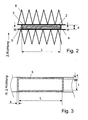
- Im Folgenden wird die Erfindung anhand eines Ausführungsbeispiels unter Bezugnahme auf die Zeichnung im Einzelnen erläutert. In der Zeichnung zeigen:
- Fig. 1
- eine Ansicht auf eine erfindungsgemäße Heizungsanordnung,
- Fig. 2
- einen vergrößerten Schnitt durch die Heizungsanordnung von
Fig. 1 entlang der Linie II-II inFig. 1 , - Fig. 3
- einen Schnitt entlang der Linie III-III in
Fig. 2 , - Fig. 4
- eine
Fig. 2 entsprechende Darstellung nach einer Zwangsentspannung, - Fig. 5
- ein elektrisches Ersatzschaubild, das die Widerstände verdeutlicht, und
- Fig. 6
- ein
Fig. 5 entsprechendes Ersatzschaubild, das die Widerstände nach einer Zwangsentspannung verdeutlicht. - Bei PTC-Heizungsanordnung 1 mit Keramik-PTC-Elementen ist jeweils ein PTC-Element 2 zwischen zwei parallel zueinander angeordneten Kontaktblechen 3 (Pluspol) und 4 (Minuspol) eingeklebt, vorliegend mittels eines Klebstoffes 5, der einen spezifischen elektrischen Widerstand von etwa 100 Ohm x cm hat. Auf den jeweils dem PTC-Element 2 gegenüberliegenden Seiten der Kontaktbleche 3 und 4 sind mittels einer entsprechenden Klebe-Verbindung Wellrippen 6 angebracht und an diesen, ebenfalls wiederum mit einer entsprechenden Klebe-Verbindung je ein weiteres Kontaktblech 3 und 4. Um die zuvor beschriebene Anordnung herum ist ein Kunststoff-Rahmen 7 angeordnet. Die Strömungsrichtung der Luft liegt bei
Fig. 1 in Blickrichtung. - Im Folgenden wird die Länge eines PTC-Elements 2 mit L, vorliegend 035 mm, die Breite des PTC-Elements 2 mit 1, vorliegend 8 mm, und die Dicke des PTC-Elements 2 mit e, vorliegend 1,4 mm, bezeichnet. Die durchschnittliche Dicke der Klebstoffschicht zwischen der Oberfläche des PTC-Elements 2 und einem Kontaktblech 3 oder 4 mit eta, vorliegend 0,01 µm, bezeichnet. Die Breite des Klebstoffes um das PTC-Element 2 zwischen den Kontaktblechen 3 und 4 wird mit s bezeichnet und beträgt vorliegend 1 mm.
- Die Spannung zwischen den Kontaktblechen 3 und 4 wird mit U bezeichnet und beträgt gemäß dem vorliegenden Ausführungsbeispiel 13 V, kann jedoch auch größer sein, bspw. 48 V.
- Der spezifische elektrische Widerstand des Klebstoffs 5 wird mit RhoKleb bezeichnet, der Widerstand des PTC-Elements 2 mit RPTC, der Widerstand der Klebstoffschicht zwischen PTC-Element 2 und Kontaktblech 3 oder 4 mit RKleb.
- Die Leistung des PTC-Elements 2 wird mit PPTC bezeichnet, die Leistung des Klebstoffes 5 zwischen den Kontaktblechen 3 und 4 mit Pb, die Leistung des PTC-Elements 2 in Verbindung mit dem Klebstoff 5 ohne Zwangsentspannung mit PKleben + PTC ohne Zwangentspannung, die Leistung des PTC-Elements 2 in Verbindung mit dem Klebstoff 5 mit Zwangsentspannung mit PKleben + PTC nach Zwangentspannung, die Gesamtleistung mit Pgesamt.
- Hierbei ergibt sich der Widerstand RKleb des Klebstoffs 5 zwischen dem PTC-Element und einem Kontaktblech 3 oder 4 bzw. der Widerstand Rb des das PTC-Element 2 umgebenden Klebstoffes 5 wie folgt:
- (1) RKleb = RhOKleb x eta / (L x l)
- (2) Rb = RhoKleb x e / (2(L+I) x s)
- Ersatzschaubilder für die Schaltungen der Widerstände sind in den
Figuren 5 und 6 dargestellt. - Die Leistung PKleben + PTC ohne Zwangentspannung ergibt sich bZW. die Leistung PKleben . + PTC nach Zwangentspannung durch
- (3) PKleben + PTC ohne Zwangentspannung = U2 / RPTC
- (4) PKleben + PTC nach Zwangentspannung = U2 / (2RKleb + RPTC)
- Um einen optimalen Wirkungsgrad des PTC-Elements 2 zu bewirken, sollte das Verhältnis PPTC/ Pb möglichst groß gewählt werden. Ferner sollte jedoch das Verhältnis von PKleben + PTC ohne Zwangentspannung / PKleben + PTC nach Zwangentspannung möglichst nahe bei 1 liegen. Dabei liegt das Verhältnis von PPTC/ Pb insbesondere zwischen ca. 4 und 40 und das Verhältnis von PKleben + PTC ohne Zwangentspannung / PKleben + PTC nach Zwangentspannung zwischen Ca. 1,2 und 1,02.
-
- 1 Heizungsanordnung
- 2 PTC-Element
- 3 Kontaktblech
- 4 Kontaktblech
- 5 Klebstoff
- 6 Wellrippe
- 7 Kunststoff-Rahmen
Claims (7)
- Heizungsanordnung mit mindestens einem PTC-Element, insbesondere für ein Kraftfahrzeug, wobei das PTC-Element (2) zwischen Kontaktblechen (3, 4) angeordnet ist, die der elektrischen Anbindung dienen, wobei die Kontaktbleche (3, 4) und das PTC-Element (2) mittels eines Klebstoffes (5) verbunden sind, dadurch gekennzeichnet, dass der Klebstoff (5) einen spezifischen elektrischen Widerstand von minimal 50 Ohm x cm und maximal 500 Ohm x cm aufweist.
- Heizungsanordnung nach Anspruch 1, dadurch gekennzeichnet, dass der Klebstoff (5) einen spezifischen elektrischen Widerstand von minimal 80 Ohm x cm und maximal 150 Ohm x cm, insbesondere von 100 Ohm x cm +/- 10% aufweist.
- Heizungsanordnung nach Anspruch 1 oder 2, dadurch gekennzeichnet, dass die Schichtdicke des Klebstoffs (5) zwischen dem PTC-Element (2) und einem Kontaktblech (3, 4) vor einer Zwangsentspannung vernachlässigbar ist und nach einer Zwangentspannung maximal 0,02 µm, insbesondere 0,01 µm +/- 10%, beträgt.
- Heizungsanordnung mit mindestens einem PTC-Element, insbesondere für ein Kraftfahrzeug, wobei das PTC-Element (2) zwischen Kontaktblechen (3, 4) angeordnet ist, die der elektrischen Anbindung dienen, wobei die Kontaktbleche (3, 4) und das PTC-Element (2) mittels eines Lots verbunden sind, dadurch gekennzeichnet, dass das Lot einen spezifischen elektrischen Widerstand von minimal 50 Ohm x cm und maximal 500 Ohm x cm aufweist.
- Heizungsanordnung nach Anspruch 4, dadurch gekennzeichnet, dass das Lot einen spezifischen elektrischen Widerstand von minimal 80 Ohm x cm und maximal 150 Ohm x cm, insbesondere von 100 Ohm x cm +/-10% aufweist.
- Heizungsanordnung nach Anspruch 4 oder 5, dadurch gekennzeichnet, dass die Schichtdicke des Lots zwischen dem PTC-Element (2) und einem Kontaktblech (3, 4) vor einer Zwangsentspannung vernachlässigbar ist und nach einer Zwangentspannung maximal 0,02 µm, insbesondere 0,01 µm +/- 10%, beträgt.
- Klebstoff oder Lot für eine Verbindung zwischen einem keramischen PTC-Element (2) und einem elektrisch leitenden Kontakblech (3, 4), dadurch gekennzeichnet, dass der Klebstoff (5) beziehungsweise das Lot einen spezifischen elektrischen Widerstand von minimal 50 Ohm x cm und maximal 500 Ohm x cm aufweist.
Priority Applications (7)
| Application Number | Priority Date | Filing Date | Title |
|---|---|---|---|
| DE50312260T DE50312260D1 (de) | 2003-10-07 | 2003-10-07 | Heizungsanordnung mit PTC-Element, insbesondere für ein Kraftfahrzeug |
| AT03292474T ATE453306T1 (de) | 2003-10-07 | 2003-10-07 | Heizungsanordnung mit ptc-element, insbesondere für ein kraftfahrzeug |
| EP03292474A EP1523225B1 (de) | 2003-10-07 | 2003-10-07 | Heizungsanordnung mit PTC-Element, insbesondere für ein Kraftfahrzeug |
| PCT/EP2004/010328 WO2005039242A1 (de) | 2003-10-07 | 2004-09-15 | Heizungsanordnung mit ptc-element, insbesondere für ein kraftfahrzeug |
| CNB2004800291073A CN100488323C (zh) | 2003-10-07 | 2004-09-15 | 用于汽车的带有ptc元件的取暖装置 |
| JP2006529988A JP2007507384A (ja) | 2003-10-07 | 2004-09-15 | Ptc素子を有する特に自動車用の暖房装置 |
| US10/574,543 US7759610B2 (en) | 2003-10-07 | 2004-09-15 | Heating assembly comprising a PTC element, in particular for a motor vehicle |
Applications Claiming Priority (1)
| Application Number | Priority Date | Filing Date | Title |
|---|---|---|---|
| EP03292474A EP1523225B1 (de) | 2003-10-07 | 2003-10-07 | Heizungsanordnung mit PTC-Element, insbesondere für ein Kraftfahrzeug |
Publications (2)
| Publication Number | Publication Date |
|---|---|
| EP1523225A1 EP1523225A1 (de) | 2005-04-13 |
| EP1523225B1 true EP1523225B1 (de) | 2009-12-23 |
Family
ID=34307027
Family Applications (1)
| Application Number | Title | Priority Date | Filing Date |
|---|---|---|---|
| EP03292474A Expired - Lifetime EP1523225B1 (de) | 2003-10-07 | 2003-10-07 | Heizungsanordnung mit PTC-Element, insbesondere für ein Kraftfahrzeug |
Country Status (7)
| Country | Link |
|---|---|
| US (1) | US7759610B2 (de) |
| EP (1) | EP1523225B1 (de) |
| JP (1) | JP2007507384A (de) |
| CN (1) | CN100488323C (de) |
| AT (1) | ATE453306T1 (de) |
| DE (1) | DE50312260D1 (de) |
| WO (1) | WO2005039242A1 (de) |
Cited By (2)
| Publication number | Priority date | Publication date | Assignee | Title |
|---|---|---|---|---|
| EP3133897A1 (de) | 2015-08-18 | 2017-02-22 | Mahle International GmbH | Elektrische heizeinrichtung und ansteuerungselektronik |
| DE102021204888A1 (de) | 2021-05-12 | 2022-11-17 | Mahle International Gmbh | PTC-Heizelement |
Families Citing this family (8)
| Publication number | Priority date | Publication date | Assignee | Title |
|---|---|---|---|---|
| FR2897744B1 (fr) * | 2006-02-17 | 2008-05-09 | Valeo Systemes Thermiques | Chassis porteur d'elements chauffants pour un radiateur electrique d'une installation de ventilation, de chauffage et/ou de climatisation. |
| EP2083607A1 (de) | 2008-01-23 | 2009-07-29 | Behr France Rouffach SAS | Vorrichtung zum Heizen insbesondere eines Kraftfahrzeuges |
| DE102010020070A1 (de) * | 2010-05-09 | 2011-11-10 | Esw Gmbh | Heizmodul zur Erwärmung strömender Medien und Verfahren zu seiner Herstellung |
| DE102012107985B4 (de) * | 2012-08-29 | 2023-06-22 | Borgwarner Ludwigsburg Gmbh | Heizstab |
| EP3401617A1 (de) * | 2017-05-12 | 2018-11-14 | Mahle International GmbH | Elektrische heizeinrichtung |
| EP3530503A1 (de) * | 2018-02-26 | 2019-08-28 | MAHLE International GmbH | Elektrische heizung |
| DE102019204665B4 (de) * | 2019-03-06 | 2026-05-07 | Eberspächer Catem Gmbh & Co. Kg | PTC-Heizelement und eine elektrische Heizvorrichtung |
| DE102020113124A1 (de) * | 2020-05-14 | 2021-11-18 | Eberspächer catem Hermsdorf GmbH & Co. KG | PTC-Heizzelle und Verfahren zu deren Herstellung |
Family Cites Families (20)
| Publication number | Priority date | Publication date | Assignee | Title |
|---|---|---|---|---|
| DE10144757B4 (de) | 2001-09-11 | 2006-03-30 | Webasto Ag | Zusatzheizung für Personenfahrzeuge |
| US4865039A (en) * | 1985-08-21 | 1989-09-12 | Spring Creek Institute | Dry electrode system for detection of biopotentials and dry electrode for making electrical and mechanical connection to a living body |
| JPH01294393A (ja) * | 1988-05-20 | 1989-11-28 | Matsushita Electric Ind Co Ltd | 面状採暖具の接着方法 |
| JPH0253628A (ja) * | 1988-08-17 | 1990-02-22 | Texas Instr Japan Ltd | 空気加熱装置 |
| JPH0320378A (ja) * | 1989-06-17 | 1991-01-29 | Fujikura Ltd | 導電性接着剤 |
| CN2080482U (zh) * | 1990-07-23 | 1991-07-10 | 刘振荣 | 汽车电暖器 |
| US5211174A (en) * | 1990-09-14 | 1993-05-18 | Physiometrix, Inc. | Low impedance, low durometer, dry conforming contact element |
| CN2125519U (zh) * | 1992-06-29 | 1992-12-23 | 北京汽车空调制造厂 | 汽车空调器 |
| US5856773A (en) * | 1996-11-04 | 1999-01-05 | Raychem Corporation | Circuit protection device |
| JPH10208902A (ja) * | 1997-01-21 | 1998-08-07 | Tdk Corp | 有機ptcサーミスタの製造方法 |
| JPH11186003A (ja) * | 1997-12-25 | 1999-07-09 | Yazaki Corp | Ptc素子の放熱構造 |
| JPH11214203A (ja) * | 1998-01-29 | 1999-08-06 | Unitika Ltd | Ptc素子及びその製造方法 |
| CN2318068Y (zh) * | 1998-04-09 | 1999-05-12 | 李有德 | 汽车保温罩 |
| JPH11308763A (ja) * | 1998-04-22 | 1999-11-05 | Ngk Insulators Ltd | Ptc素子を備えた限流器およびこの限流器を備えた遮断器 |
| JP4092805B2 (ja) * | 1999-03-19 | 2008-05-28 | 株式会社デンソー | 車両用空調装置 |
| ATE238639T1 (de) * | 2000-08-25 | 2003-05-15 | Catem Gmbh & Co Kg | Ptc-heizvorrichtung mit klebstoff |
| JP2002367810A (ja) * | 2001-06-11 | 2002-12-20 | Nec Tokin Corp | 高分子ptc素子及びその製造方法 |
| JP2003037002A (ja) * | 2001-07-24 | 2003-02-07 | Mitsubishi Electric Corp | 限流器とその製造方法 |
| US6659783B2 (en) * | 2001-08-01 | 2003-12-09 | Tyco Electronics Corp | Electrical connector including variable resistance to reduce arcing |
| JP5087888B2 (ja) | 2006-08-28 | 2012-12-05 | ソニー株式会社 | 固体撮像装置及びその製造方法 |
-
2003
- 2003-10-07 DE DE50312260T patent/DE50312260D1/de not_active Expired - Lifetime
- 2003-10-07 EP EP03292474A patent/EP1523225B1/de not_active Expired - Lifetime
- 2003-10-07 AT AT03292474T patent/ATE453306T1/de not_active IP Right Cessation
-
2004
- 2004-09-15 CN CNB2004800291073A patent/CN100488323C/zh not_active Expired - Fee Related
- 2004-09-15 US US10/574,543 patent/US7759610B2/en not_active Expired - Fee Related
- 2004-09-15 JP JP2006529988A patent/JP2007507384A/ja active Pending
- 2004-09-15 WO PCT/EP2004/010328 patent/WO2005039242A1/de not_active Ceased
Cited By (3)
| Publication number | Priority date | Publication date | Assignee | Title |
|---|---|---|---|---|
| EP3133897A1 (de) | 2015-08-18 | 2017-02-22 | Mahle International GmbH | Elektrische heizeinrichtung und ansteuerungselektronik |
| DE102015215748A1 (de) | 2015-08-18 | 2017-02-23 | Mahle International Gmbh | Elektrische Heizeinrichtung und Ansteuerungselektronik |
| DE102021204888A1 (de) | 2021-05-12 | 2022-11-17 | Mahle International Gmbh | PTC-Heizelement |
Also Published As
| Publication number | Publication date |
|---|---|
| WO2005039242A1 (de) | 2005-04-28 |
| JP2007507384A (ja) | 2007-03-29 |
| CN1902983A (zh) | 2007-01-24 |
| EP1523225A1 (de) | 2005-04-13 |
| CN100488323C (zh) | 2009-05-13 |
| ATE453306T1 (de) | 2010-01-15 |
| US7759610B2 (en) | 2010-07-20 |
| US20070000902A1 (en) | 2007-01-04 |
| DE50312260D1 (de) | 2010-02-04 |
Similar Documents
| Publication | Publication Date | Title |
|---|---|---|
| DE60308022T2 (de) | Beheizter spiegel | |
| DE60219518T2 (de) | Beheizbare scheibe versehen mit einer elektroleitenden beschichtung | |
| DE69618844T2 (de) | Heizeinrichtung für Kraftfahrzeugscheibe | |
| DE68918539T2 (de) | Heizgerät mit positivem Temperaturkoeffizienten. | |
| EP3243361B1 (de) | Transparente scheibe mit elektrischer heizschicht, sowie herstellungsverfahren hierfür | |
| EP2405708A1 (de) | Transparente Scheibe mit heizbarer Beschichtung | |
| DE212012000003U1 (de) | Transparente Scheibe mit elektrischer Heizschicht | |
| EP1772684A2 (de) | Elektrisches Heizmodul zur Luftstromerwärmung, insbesondere zur Heizung und Belüftung von Sitzen | |
| DE69313185T2 (de) | Gebläsemotorregler für ein Kraftfahrzeugbelüftungssystem | |
| DE112018004669T5 (de) | Lötfreier flexibler verbinder mit hoher leistung für gedruckte leiterbahnen | |
| DE60309722T2 (de) | Beheizbare scheibenwischerauflagefläche für eine transparenz | |
| DE102019208130A1 (de) | PTC-Heizelement und eine elektrische Heizvorrichtung | |
| EP1523225A1 (de) | Heizungsanordnung mit PTC-Element, insbesondere für ein Kraftfahrzeug | |
| EP1523226B1 (de) | Heizungsanordnung mit PTC-Element, insbesondere für ein Kraftfahrzeug | |
| WO2004080738A1 (de) | Elektrische heizeinrichtung, insbesondere für kraftfahrzeuge | |
| EP0155614A2 (de) | Elektrisch beheizbare Verbundglasscheibe | |
| EP1621378A1 (de) | Heizungsanordnung mit einem Heizelement, insbesondere für ein Kraftfahrzeug | |
| EP1522439B2 (de) | Heizungsanordnung mit PTC-Element, insbesondere für ein Kraftfahrzeug | |
| DE112020000971T5 (de) | Flexible und dehnbare Elektroheizung basierend auf einem elektrisch leitenden Textilmaterial und Verfahren zur Herstellung von dieser | |
| EP0110121A1 (de) | Elektrischer Heizbelag für Spiegel | |
| EP1926346B1 (de) | Elektrische Heizungsvorrichtung, insbesondere für ein Kraftfahrzeug | |
| DE102007001080A1 (de) | Elektrisch beheizbare Fensterscheibe | |
| EP2109347B1 (de) | Elektrische Vorrichtung zum Heizen insbesondere eines Kraftfahrzeuges | |
| DE3543673A1 (de) | Einrichtung zum heizen | |
| DE102006001791A1 (de) | Vorwiderstand |
Legal Events
| Date | Code | Title | Description |
|---|---|---|---|
| PUAI | Public reference made under article 153(3) epc to a published international application that has entered the european phase |
Free format text: ORIGINAL CODE: 0009012 |
|
| AK | Designated contracting states |
Kind code of ref document: A1 Designated state(s): AT BE BG CH CY CZ DE DK EE ES FI FR GB GR HU IE IT LI LU MC NL PT RO SE SI SK TR |
|
| AX | Request for extension of the european patent |
Extension state: AL LT LV MK |
|
| RAP1 | Party data changed (applicant data changed or rights of an application transferred) |
Owner name: BEHR FRANCE ROUFFACH SAS |
|
| 17P | Request for examination filed |
Effective date: 20051013 |
|
| AKX | Designation fees paid |
Designated state(s): AT BE BG CH CY CZ DE DK EE ES FI FR GB GR HU IE IT LI LU MC NL PT RO SE SI SK TR |
|
| GRAP | Despatch of communication of intention to grant a patent |
Free format text: ORIGINAL CODE: EPIDOSNIGR1 |
|
| GRAS | Grant fee paid |
Free format text: ORIGINAL CODE: EPIDOSNIGR3 |
|
| GRAA | (expected) grant |
Free format text: ORIGINAL CODE: 0009210 |
|
| AK | Designated contracting states |
Kind code of ref document: B1 Designated state(s): AT BE BG CH CY CZ DE DK EE ES FI FR GB GR HU IE IT LI LU MC NL PT RO SE SI SK TR |
|
| REG | Reference to a national code |
Ref country code: GB Ref legal event code: FG4D Free format text: NOT ENGLISH |
|
| REG | Reference to a national code |
Ref country code: CH Ref legal event code: EP |
|
| REG | Reference to a national code |
Ref country code: IE Ref legal event code: FG4D |
|
| REF | Corresponds to: |
Ref document number: 50312260 Country of ref document: DE Date of ref document: 20100204 Kind code of ref document: P |
|
| REG | Reference to a national code |
Ref country code: NL Ref legal event code: VDEP Effective date: 20091223 |
|
| PG25 | Lapsed in a contracting state [announced via postgrant information from national office to epo] |
Ref country code: SE Free format text: LAPSE BECAUSE OF FAILURE TO SUBMIT A TRANSLATION OF THE DESCRIPTION OR TO PAY THE FEE WITHIN THE PRESCRIBED TIME-LIMIT Effective date: 20091223 Ref country code: FI Free format text: LAPSE BECAUSE OF FAILURE TO SUBMIT A TRANSLATION OF THE DESCRIPTION OR TO PAY THE FEE WITHIN THE PRESCRIBED TIME-LIMIT Effective date: 20091223 |
|
| PG25 | Lapsed in a contracting state [announced via postgrant information from national office to epo] |
Ref country code: SI Free format text: LAPSE BECAUSE OF FAILURE TO SUBMIT A TRANSLATION OF THE DESCRIPTION OR TO PAY THE FEE WITHIN THE PRESCRIBED TIME-LIMIT Effective date: 20091223 |
|
| REG | Reference to a national code |
Ref country code: IE Ref legal event code: FD4D |
|
| PG25 | Lapsed in a contracting state [announced via postgrant information from national office to epo] |
Ref country code: PT Free format text: LAPSE BECAUSE OF FAILURE TO SUBMIT A TRANSLATION OF THE DESCRIPTION OR TO PAY THE FEE WITHIN THE PRESCRIBED TIME-LIMIT Effective date: 20100423 Ref country code: NL Free format text: LAPSE BECAUSE OF FAILURE TO SUBMIT A TRANSLATION OF THE DESCRIPTION OR TO PAY THE FEE WITHIN THE PRESCRIBED TIME-LIMIT Effective date: 20091223 Ref country code: ES Free format text: LAPSE BECAUSE OF FAILURE TO SUBMIT A TRANSLATION OF THE DESCRIPTION OR TO PAY THE FEE WITHIN THE PRESCRIBED TIME-LIMIT Effective date: 20100403 Ref country code: EE Free format text: LAPSE BECAUSE OF FAILURE TO SUBMIT A TRANSLATION OF THE DESCRIPTION OR TO PAY THE FEE WITHIN THE PRESCRIBED TIME-LIMIT Effective date: 20091223 Ref country code: RO Free format text: LAPSE BECAUSE OF FAILURE TO SUBMIT A TRANSLATION OF THE DESCRIPTION OR TO PAY THE FEE WITHIN THE PRESCRIBED TIME-LIMIT Effective date: 20091223 Ref country code: BG Free format text: LAPSE BECAUSE OF FAILURE TO SUBMIT A TRANSLATION OF THE DESCRIPTION OR TO PAY THE FEE WITHIN THE PRESCRIBED TIME-LIMIT Effective date: 20100323 |
|
| PG25 | Lapsed in a contracting state [announced via postgrant information from national office to epo] |
Ref country code: CZ Free format text: LAPSE BECAUSE OF FAILURE TO SUBMIT A TRANSLATION OF THE DESCRIPTION OR TO PAY THE FEE WITHIN THE PRESCRIBED TIME-LIMIT Effective date: 20091223 Ref country code: SK Free format text: LAPSE BECAUSE OF FAILURE TO SUBMIT A TRANSLATION OF THE DESCRIPTION OR TO PAY THE FEE WITHIN THE PRESCRIBED TIME-LIMIT Effective date: 20091223 |
|
| PG25 | Lapsed in a contracting state [announced via postgrant information from national office to epo] |
Ref country code: IE Free format text: LAPSE BECAUSE OF FAILURE TO SUBMIT A TRANSLATION OF THE DESCRIPTION OR TO PAY THE FEE WITHIN THE PRESCRIBED TIME-LIMIT Effective date: 20091223 Ref country code: GR Free format text: LAPSE BECAUSE OF FAILURE TO SUBMIT A TRANSLATION OF THE DESCRIPTION OR TO PAY THE FEE WITHIN THE PRESCRIBED TIME-LIMIT Effective date: 20100324 Ref country code: CY Free format text: LAPSE BECAUSE OF FAILURE TO SUBMIT A TRANSLATION OF THE DESCRIPTION OR TO PAY THE FEE WITHIN THE PRESCRIBED TIME-LIMIT Effective date: 20091223 |
|
| PLBE | No opposition filed within time limit |
Free format text: ORIGINAL CODE: 0009261 |
|
| STAA | Information on the status of an ep patent application or granted ep patent |
Free format text: STATUS: NO OPPOSITION FILED WITHIN TIME LIMIT |
|
| 26N | No opposition filed |
Effective date: 20100924 |
|
| PG25 | Lapsed in a contracting state [announced via postgrant information from national office to epo] |
Ref country code: DK Free format text: LAPSE BECAUSE OF FAILURE TO SUBMIT A TRANSLATION OF THE DESCRIPTION OR TO PAY THE FEE WITHIN THE PRESCRIBED TIME-LIMIT Effective date: 20091223 |
|
| PG25 | Lapsed in a contracting state [announced via postgrant information from national office to epo] |
Ref country code: IT Free format text: LAPSE BECAUSE OF FAILURE TO SUBMIT A TRANSLATION OF THE DESCRIPTION OR TO PAY THE FEE WITHIN THE PRESCRIBED TIME-LIMIT Effective date: 20091223 |
|
| BERE | Be: lapsed |
Owner name: BEHR FRANCE ROUFFACH SAS Effective date: 20101031 |
|
| PG25 | Lapsed in a contracting state [announced via postgrant information from national office to epo] |
Ref country code: MC Free format text: LAPSE BECAUSE OF NON-PAYMENT OF DUE FEES Effective date: 20101031 |
|
| REG | Reference to a national code |
Ref country code: CH Ref legal event code: PL |
|
| PG25 | Lapsed in a contracting state [announced via postgrant information from national office to epo] |
Ref country code: CH Free format text: LAPSE BECAUSE OF NON-PAYMENT OF DUE FEES Effective date: 20101031 Ref country code: LI Free format text: LAPSE BECAUSE OF NON-PAYMENT OF DUE FEES Effective date: 20101031 |
|
| PG25 | Lapsed in a contracting state [announced via postgrant information from national office to epo] |
Ref country code: BE Free format text: LAPSE BECAUSE OF NON-PAYMENT OF DUE FEES Effective date: 20101031 |
|
| REG | Reference to a national code |
Ref country code: AT Ref legal event code: MM01 Ref document number: 453306 Country of ref document: AT Kind code of ref document: T Effective date: 20101007 |
|
| PG25 | Lapsed in a contracting state [announced via postgrant information from national office to epo] |
Ref country code: AT Free format text: LAPSE BECAUSE OF NON-PAYMENT OF DUE FEES Effective date: 20101007 |
|
| PG25 | Lapsed in a contracting state [announced via postgrant information from national office to epo] |
Ref country code: LU Free format text: LAPSE BECAUSE OF NON-PAYMENT OF DUE FEES Effective date: 20101007 Ref country code: HU Free format text: LAPSE BECAUSE OF FAILURE TO SUBMIT A TRANSLATION OF THE DESCRIPTION OR TO PAY THE FEE WITHIN THE PRESCRIBED TIME-LIMIT Effective date: 20100624 |
|
| PG25 | Lapsed in a contracting state [announced via postgrant information from national office to epo] |
Ref country code: TR Free format text: LAPSE BECAUSE OF FAILURE TO SUBMIT A TRANSLATION OF THE DESCRIPTION OR TO PAY THE FEE WITHIN THE PRESCRIBED TIME-LIMIT Effective date: 20091223 |
|
| REG | Reference to a national code |
Ref country code: DE Ref legal event code: R082 Ref document number: 50312260 Country of ref document: DE Representative=s name: GRAUEL, ANDREAS, DIPL.-PHYS. DR. RER. NAT., DE Ref country code: DE Ref legal event code: R081 Ref document number: 50312260 Country of ref document: DE Owner name: MAHLE INTERNATIONAL GMBH, DE Free format text: FORMER OWNER: BEHR FRANCE ROUFFACH S.A.S., ROUFFACH, FR |
|
| REG | Reference to a national code |
Ref country code: FR Ref legal event code: PLFP Year of fee payment: 13 |
|
| REG | Reference to a national code |
Ref country code: FR Ref legal event code: PLFP Year of fee payment: 14 |
|
| REG | Reference to a national code |
Ref country code: FR Ref legal event code: PLFP Year of fee payment: 15 |
|
| REG | Reference to a national code |
Ref country code: FR Ref legal event code: PLFP Year of fee payment: 16 |
|
| PGFP | Annual fee paid to national office [announced via postgrant information from national office to epo] |
Ref country code: GB Payment date: 20181024 Year of fee payment: 16 Ref country code: FR Payment date: 20181026 Year of fee payment: 16 |
|
| GBPC | Gb: european patent ceased through non-payment of renewal fee |
Effective date: 20191007 |
|
| PG25 | Lapsed in a contracting state [announced via postgrant information from national office to epo] |
Ref country code: GB Free format text: LAPSE BECAUSE OF NON-PAYMENT OF DUE FEES Effective date: 20191007 Ref country code: FR Free format text: LAPSE BECAUSE OF NON-PAYMENT OF DUE FEES Effective date: 20191031 |
|
| PGFP | Annual fee paid to national office [announced via postgrant information from national office to epo] |
Ref country code: DE Payment date: 20201216 Year of fee payment: 18 |
|
| REG | Reference to a national code |
Ref country code: DE Ref legal event code: R119 Ref document number: 50312260 Country of ref document: DE |
|
| PG25 | Lapsed in a contracting state [announced via postgrant information from national office to epo] |
Ref country code: DE Free format text: LAPSE BECAUSE OF NON-PAYMENT OF DUE FEES Effective date: 20220503 |