EP3530503A1 - Elektrische heizung - Google Patents
Elektrische heizung Download PDFInfo
- Publication number
- EP3530503A1 EP3530503A1 EP18158516.7A EP18158516A EP3530503A1 EP 3530503 A1 EP3530503 A1 EP 3530503A1 EP 18158516 A EP18158516 A EP 18158516A EP 3530503 A1 EP3530503 A1 EP 3530503A1
- Authority
- EP
- European Patent Office
- Prior art keywords
- elements
- metallic sheet
- heating
- electric heater
- spacers
- Prior art date
- Legal status (The legal status is an assumption and is not a legal conclusion. Google has not performed a legal analysis and makes no representation as to the accuracy of the status listed.)
- Withdrawn
Links
Images


Classifications
-
- H—ELECTRICITY
- H05—ELECTRIC TECHNIQUES NOT OTHERWISE PROVIDED FOR
- H05B—ELECTRIC HEATING; ELECTRIC LIGHT SOURCES NOT OTHERWISE PROVIDED FOR; CIRCUIT ARRANGEMENTS FOR ELECTRIC LIGHT SOURCES, IN GENERAL
- H05B3/00—Ohmic-resistance heating
- H05B3/40—Heating elements having the shape of rods or tubes
- H05B3/42—Heating elements having the shape of rods or tubes non-flexible
- H05B3/48—Heating elements having the shape of rods or tubes non-flexible heating conductor embedded in insulating material
- H05B3/50—Heating elements having the shape of rods or tubes non-flexible heating conductor embedded in insulating material heating conductor arranged in metal tubes, the radiating surface having heat-conducting fins
-
- F—MECHANICAL ENGINEERING; LIGHTING; HEATING; WEAPONS; BLASTING
- F24—HEATING; RANGES; VENTILATING
- F24H—FLUID HEATERS, e.g. WATER OR AIR HEATERS, HAVING HEAT-GENERATING MEANS, e.g. HEAT PUMPS, IN GENERAL
- F24H3/00—Air heaters
- F24H3/02—Air heaters with forced circulation
- F24H3/04—Air heaters with forced circulation the air being in direct contact with the heating medium, e.g. electric heating element
- F24H3/0405—Air heaters with forced circulation the air being in direct contact with the heating medium, e.g. electric heating element using electric energy supply, e.g. the heating medium being a resistive element; Heating by direct contact, i.e. with resistive elements, electrodes and fins being bonded together without additional element in-between
-
- F—MECHANICAL ENGINEERING; LIGHTING; HEATING; WEAPONS; BLASTING
- F24—HEATING; RANGES; VENTILATING
- F24H—FLUID HEATERS, e.g. WATER OR AIR HEATERS, HAVING HEAT-GENERATING MEANS, e.g. HEAT PUMPS, IN GENERAL
- F24H9/00—Details
- F24H9/18—Arrangement or mounting of grates or heating means
- F24H9/1854—Arrangement or mounting of grates or heating means for air heaters
- F24H9/1863—Arrangement or mounting of electric heating means
-
- H—ELECTRICITY
- H05—ELECTRIC TECHNIQUES NOT OTHERWISE PROVIDED FOR
- H05B—ELECTRIC HEATING; ELECTRIC LIGHT SOURCES NOT OTHERWISE PROVIDED FOR; CIRCUIT ARRANGEMENTS FOR ELECTRIC LIGHT SOURCES, IN GENERAL
- H05B2203/00—Aspects relating to Ohmic resistive heating covered by group H05B3/00
- H05B2203/022—Heaters specially adapted for heating gaseous material
- H05B2203/023—Heaters of the type used for electrically heating the air blown in a vehicle compartment by the vehicle heating system
Definitions
- the invention relates to an electric heater, especially as auxiliary heater of an air-conditioning unit of a motor vehicle.
- Electric heaters are known in the art EP 0 350 528 A1 discloses a web of ceramic heating elements which are each located between two metallic sheet elements to electrically contact the ceramic heating elements.
- the assembly of the ceramic heating elements and the two respective metallic sheet elements is considered as a heating-emitting element.
- an electric heater contains a plurality of such heat-emitting elements while between two of such heat-emitting elements an undulating fin element is located thermally contacting the two heating members such that the undulating fin element contacts two metallic sheet elements of adjacent heat-emitting elements.
- On the outer length sides of the web metallic sheet elements are arranged to provide side members for the adjacent located spring means.
- the web is arranged in a frame structure having elastic spring means to compress the web perpendicular to the length direction of the heat-emitting elements in order to achieve both a good electrical contact between the ceramic heating elements and the respective contacting metallic sheet elements and a good thermal contact between the metallic sheet elements and the respective undulating fin element.
- Such an electric heater uses a high number of parts necessary for thermal and electrical properties which have to be assembled. Therefore the above described electric heater is quite expensive in terms of production and logistics.
- an electric heater having a web of a plurality of heating elements which are each electrically contacted on a first side by a respective metallic sheet element, the assembly of the heating elements and the respective metallic sheet element is considered as a heating-emitting element, furthermore undulating fin elements are provided such that an undulating fin element is contacting the respective heating element on a second side adjacent of the first side with a first side of the undulating fin element, wherein the undulated fin element is furthermore contacting a metallic sheet element with a second side of the undulating fin element, such that the metallic sheet element contacted by the undulating fin element is a metallic sheet element of an adjacent heat-emitting element, wherein the heating elements are glued to the metallic sheet element and to the undulating fin element and the undulating fin elements are furthermore glued to the respective metallic sheet elements of the adjacent heat-emitting elements. Therefore, it is possible to reduce the amount of parts used to reduce manufacturing costs of the electric heater and to reduce weight. Accordingly, the
- At least one electrically non-conducting spacer or a plurality of electrically non-conducting spacers is/are provided which is/are located between the respective metallic sheet element and the undulating fin element laterally between heating elements or adjacent to a heating element. This allows a strong and rigid structure since the undulating fin elements have a defined position even between the heating elements.
- the spacer or the spacers has/have at least almost the same thickness as the adjacent heating element, wherein the thickness is measured in the direction perpendicular of the plane of the larger dimensions of the heating element. Therefore, the undulating fin element has the same shape contacting the spacer or contacting the heating element and no unavoided structural changes occur.
- the spacer is made of a plastic material. Therefore, the spacer is not electrically conducting and can be manufactured by cost efficient methods and techniques.
- a plurality of spacers are connected using connecting ribs between two respective spacers. Therefore, the spacers of a row respectively of a heat-emitting element can be made as one piece in order to allow a more efficient assembling.
- connecting ribs and the spacers are made in one piece e.g. by means of extrusion. This allows a cost efficient manufacturing.
- the object is furthermore achieved by an electric heater according the features of claim 7.
- an electric heater having a web of a plurality of heating elements which are each electrically contacted on a first side by a respective metallic sheet element and on a second side by another respective metallic sheet element, the assembly of the heating elements and the respective metallic sheet elements is considered as a heating-emitting element, furthermore undulating fin elements are provided such that an undulating fin element is contacting the respective metallic sheet elements, wherein the heating elements are glued to the metallic sheet elements and the metallic sheet elements are glued to the undulating fin elements, wherein at least one electrically non-conducting spacer or a plurality of electrically non-conducting spacers are provided which is/are located between the respective metallic sheet elements laterally between heating elements or adjacent to a heating element.
- the spacer or the spacers has/have at least almost the same thickness as the adjacent heating element, wherein the thickness is measured in the direction perpendicular of the plane of the larger dimensions of the heating element.
- the length of a spacer located between two heating elements is larger than the length of a heating element in the length direction of the heating element. Therefore, this allows a more even heat distribution along the heat-emitting element.
- the length of a spacer located between two heating elements is the double or more than the double of the length of a heating element in the length direction of the heating element.
- the spacer is made of a plastic material. This allows a more efficient manufacturing of the spacer using a more cost-efficient material.
- connecting ribs and the spacers are made in one piece e.g. by means of extrusion.
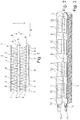
- Figure 1 shows a schematic side view of a part of an embodiment of an electric heater 1.
- the electric heater 1 comprises a web 2 of a plurality of heating elements 3 which are each electrically contacted on a first side 4 by a respective metallic sheet element 5.
- the metallic sheet element 5 is typically made as metal strip, especially made from aluminum. The metallic sheet element 5 contacts the heating elements 3 from a row of heating elements 3.
- the assembly of the heating elements 3 and the respective metallic sheet element 5 is considered as a heating-emitting element 6.
- the web 2 furthermore comprises undulating fin elements 7 which are provided such that an undulating fin element 7 is contacting the respective heating element 3 or the heating elements 3 of a row of heating elements 3 on a second side 8 adjacent of the first side 4 with a first side of the undulating fin element 7.
- the undulating fin element 7 is furthermore contacting a metallic sheet element 5 with a second side of the undulating fin element 7, such that the metallic sheet element 5 contacted by the undulating fin element 7 is a metallic sheet element 5 of an adjacent heat-emitting element 6.
- the heating elements 3 are glued to the respective metallic sheet element 5 and to the respective undulating fin element 7 and the undulating fin elements 7 are furthermore glued to the respective metallic sheet elements 5 of the adjacent heat-emitting elements 6.
- the heat-emitting elements 6 comprise furthermore at least one electrically non-conducting spacer 9.
- a plurality of electrically non-conducting spacers 9 might be provided which is/are located between the respective metallic sheet element 5 and the undulating fin element 7 and laterally between heating elements 3 or adjacent to a heating element 3 of a row of heating elements 3.
- the heating elements 3 and the spacers 9 are arranged in the same plane. They are contacted by the metallic sheet elements 5 on one side and by the undulating fin elements 7 on the other side.
- the spacer 9 or the spacers 9 has/have at least almost the same thickness d as the adjacent heating element 3, wherein the thickness is measured in the direction x perpendicular of the plane p of the larger dimensions of the heating element 3. Therefore, the undulating fin elements 7 and the metallic sheet elements 5 are contacting the heating elements 3 and the spacers 9 in a plane respectively.
- the spacers 9 are made of a plastic material e.g. by plastic extrusion or molding.
- a plurality of spacers 9 are provided which are connected using connecting ribs 10 between two respective spacers 9.
- the location of the ribs 10 is such that only one rib is provided between two adjacent spacers 9.
- the ribs 10 are located alternatively on a front edge or on a back edge of the metallic sheet element 5.
- the connecting ribs 10 and the spacers 9 of one heat-emitting element 6 are made in one piece e.g. by means of extrusion or molding.
- a plurality of spacers 9 are provided which are connected using connecting ribs 10 between two respective spacers 9.
- the location of the ribs 10 is such that only one rib is provided between two adjacent spacers 9.
- the ribs 10 are located on one side or edge of the metallic sheet element 5 such that they are located aligned in one line.
- Figure 6 shows another embodiment, where only three heating elements 3 are provided such that one end 11 of the heat-emitting element 6 is provided without a heating element 3.
- a connecting portion 12 is provided at one end of the metallic sheet elements 5 to allow electric and mechanic contact to a power supply.
- the connecting portion 12 is riveted to the metallic sheet element 5 using a rivet element 13.
- Other connecting techniques are possible too, like crimping, welding, soldering etc.
- FIG. 7 shows a schematic side view of a part of another embodiment of an electric heater 51.
- the electric heater 51 comprises a web 52 of a plurality of heating elements 53 which are each electrically contacted on a first side 54 by a respective metallic sheet element 55 and on a second side 56 by another respective metallic sheet element 55.
- the assembly of the heating elements 53 and the respective metallic sheet elements 55 on both sides of the heating elements 53 is considered as a heating-emitting element 57.
- undulating fin elements 58 are provided such that an undulating fin element 58 is contacting the respective metallic sheet elements 55.
- the undulating fin element 58 is on both sides connected by a metallic sheet element 55 of two different heat-emitting elements 57.
- the heating elements 53 are glued to the metallic sheet elements 55 and the metallic sheet elements 55 are glued to the undulating fin elements 58.
- At least one electrically non-conducting spacer 59 or a plurality of electrically non-conducting spacers 59 is/are provided which is/are located between the respective metallic sheet elements 55 and laterally between heating elements 53 or adjacent to a heating element 53.
- the spacer 59 or the spacers 59 has/have at least almost the same thickness d as the adjacent heating element 53, wherein the thickness d is measured in the direction X perpendicular of the plane P of the larger dimensions of the heating element 53.
- the length L of a spacer 59 located between two heating elements 53 is larger than the length I of a heating element 53 in the length direction Y of the heating element 53.
- the length L of a spacer 59 located between two heating elements 53 is the double or more than the double of the length I of a heating element 53 in the length direction Y of the heating element 53.
- the spacer 59 is made of a plastic material.
- a plurality of spacers 59 are connected using connecting ribs 60 between two respective spacers 59.
- the location of the ribs might be as described above with respect to Figures 2 to 6 .
- connecting ribs 60 and the spacers 59 are made in one piece e.g. by means of extrusion or molding.
- Figures 9 and 10 show embodiments of two-dimensional arrangements of heating elements 103 between metallic sheet elements 102 of electric heaters 101.
- the heating elements 103 are surrounded by electrically non-conducting frame elements 105 which have almost the same thickness d in height direction as the heating elements 103.
- the frame elements 105 have openings which are aligned in lines as shown in Figure 10 or which are located offset to each other as can be seen in Figure 9 .
Landscapes
- Engineering & Computer Science (AREA)
- Physics & Mathematics (AREA)
- Thermal Sciences (AREA)
- Chemical & Material Sciences (AREA)
- Combustion & Propulsion (AREA)
- Mechanical Engineering (AREA)
- General Engineering & Computer Science (AREA)
- Resistance Heating (AREA)
Priority Applications (1)
| Application Number | Priority Date | Filing Date | Title |
|---|---|---|---|
| EP18158516.7A EP3530503A1 (de) | 2018-02-26 | 2018-02-26 | Elektrische heizung |
Applications Claiming Priority (1)
| Application Number | Priority Date | Filing Date | Title |
|---|---|---|---|
| EP18158516.7A EP3530503A1 (de) | 2018-02-26 | 2018-02-26 | Elektrische heizung |
Publications (1)
| Publication Number | Publication Date |
|---|---|
| EP3530503A1 true EP3530503A1 (de) | 2019-08-28 |
Family
ID=61386716
Family Applications (1)
| Application Number | Title | Priority Date | Filing Date |
|---|---|---|---|
| EP18158516.7A Withdrawn EP3530503A1 (de) | 2018-02-26 | 2018-02-26 | Elektrische heizung |
Country Status (1)
| Country | Link |
|---|---|
| EP (1) | EP3530503A1 (de) |
Cited By (1)
| Publication number | Priority date | Publication date | Assignee | Title |
|---|---|---|---|---|
| AT526909A1 (de) * | 2023-02-03 | 2024-08-15 | Ebner Ind Ofenbau | Heizvorrichtung |
Citations (7)
| Publication number | Priority date | Publication date | Assignee | Title |
|---|---|---|---|---|
| EP0350528A1 (de) | 1988-07-15 | 1990-01-17 | David & Baader DBK Spezialfabrik elektrischer Apparate und Heizwiderstände GmbH | Radiator |
| EP1445553A1 (de) * | 2003-01-24 | 2004-08-11 | Behr France S.A.R.L. | Vorrichtung zum Austausch von Wärme |
| US20070000902A1 (en) * | 2003-10-07 | 2007-01-04 | Michel Brun | Heating assembly comprising a ptc element, in particular for a motor vehicle |
| US20140124494A1 (en) * | 2012-11-05 | 2014-05-08 | Betacera Inc. | Car interior compartment heater |
| EP2865963A1 (de) * | 2013-10-22 | 2015-04-29 | Mahle Behr France Rouffach S.A.S | Elektrischer Heizofen |
| DE202015104346U1 (de) * | 2015-08-18 | 2015-10-05 | Betacera Inc. | Keramikheizer mit vergrößerter Windseitenfläche |
| DE202017106418U1 (de) * | 2017-10-24 | 2017-11-08 | Betacera Inc. | Thermistorheizeinrichtung mit Wärmeableitungsstruktur |
-
2018
- 2018-02-26 EP EP18158516.7A patent/EP3530503A1/de not_active Withdrawn
Patent Citations (8)
| Publication number | Priority date | Publication date | Assignee | Title |
|---|---|---|---|---|
| EP0350528A1 (de) | 1988-07-15 | 1990-01-17 | David & Baader DBK Spezialfabrik elektrischer Apparate und Heizwiderstände GmbH | Radiator |
| EP1445553A1 (de) * | 2003-01-24 | 2004-08-11 | Behr France S.A.R.L. | Vorrichtung zum Austausch von Wärme |
| EP1445553B1 (de) * | 2003-01-24 | 2013-08-28 | Behr France Rouffach SAS | Vorrichtung zum Austausch von Wärme |
| US20070000902A1 (en) * | 2003-10-07 | 2007-01-04 | Michel Brun | Heating assembly comprising a ptc element, in particular for a motor vehicle |
| US20140124494A1 (en) * | 2012-11-05 | 2014-05-08 | Betacera Inc. | Car interior compartment heater |
| EP2865963A1 (de) * | 2013-10-22 | 2015-04-29 | Mahle Behr France Rouffach S.A.S | Elektrischer Heizofen |
| DE202015104346U1 (de) * | 2015-08-18 | 2015-10-05 | Betacera Inc. | Keramikheizer mit vergrößerter Windseitenfläche |
| DE202017106418U1 (de) * | 2017-10-24 | 2017-11-08 | Betacera Inc. | Thermistorheizeinrichtung mit Wärmeableitungsstruktur |
Cited By (2)
| Publication number | Priority date | Publication date | Assignee | Title |
|---|---|---|---|---|
| AT526909A1 (de) * | 2023-02-03 | 2024-08-15 | Ebner Ind Ofenbau | Heizvorrichtung |
| AT526909B1 (de) * | 2023-02-03 | 2025-06-15 | Ebner Ind Ofenbau | Heizvorrichtung |
Similar Documents
| Publication | Publication Date | Title |
|---|---|---|
| EP3524900B1 (de) | Heizvorrichtung für ein motorfahrzeug | |
| US8084721B2 (en) | Electrical heating apparatus, method of manufacturing heat generator unit and pressing jig for use in manufacturing thereof | |
| US5562844A (en) | Ptc heater radiator with frame members applying pressure to heaters | |
| US7482557B2 (en) | Lamella type radiator element having foldable projections and a notch | |
| EP3499655B1 (de) | Stromsammelschiene | |
| US20110240631A1 (en) | Electrical heating unit, particularly for cars | |
| JP4579282B2 (ja) | 電気ヒータ装置 | |
| US10770848B2 (en) | Connecting element | |
| US7098429B2 (en) | Heat exchanger, particularly for a heating or air conditioning unit in a motor vehicle | |
| US8642926B2 (en) | Electric heating system, in particular for use as an auxiliary heating system for automobiles | |
| EP3530503A1 (de) | Elektrische heizung | |
| KR102002378B1 (ko) | Ptc 히터의 ptc 코어 구조 | |
| EP1731852B1 (de) | Elektrischer Heizer für Fahrzeugventilationsanordnung | |
| KR102107968B1 (ko) | 전기 커넥터 | |
| KR102002376B1 (ko) | Ptc 히터의 ptc 로드의 구조 | |
| JP6982390B2 (ja) | 車両用空調装置の電気式ヒータの製造方法 | |
| CN103884092B (zh) | 车辆加热器及其制造方法 | |
| US20050103469A1 (en) | Device for exchanging heat | |
| JP7727196B2 (ja) | 電気式ヒータ | |
| JP6568738B2 (ja) | 電気式ヒータ | |
| JP6513522B2 (ja) | 電気式ヒータ | |
| US3453585A (en) | Embossed zigzag resistor grid | |
| CN223872416U (zh) | 楔形电极 | |
| EP3930423B1 (de) | Heizmodul für eine heizvorrichtung | |
| EP3540326A1 (de) | Elektrischer heizofen |
Legal Events
| Date | Code | Title | Description |
|---|---|---|---|
| PUAI | Public reference made under article 153(3) epc to a published international application that has entered the european phase |
Free format text: ORIGINAL CODE: 0009012 |
|
| STAA | Information on the status of an ep patent application or granted ep patent |
Free format text: STATUS: THE APPLICATION HAS BEEN PUBLISHED |
|
| AK | Designated contracting states |
Kind code of ref document: A1 Designated state(s): AL AT BE BG CH CY CZ DE DK EE ES FI FR GB GR HR HU IE IS IT LI LT LU LV MC MK MT NL NO PL PT RO RS SE SI SK SM TR |
|
| AX | Request for extension of the european patent |
Extension state: BA ME |
|
| STAA | Information on the status of an ep patent application or granted ep patent |
Free format text: STATUS: REQUEST FOR EXAMINATION WAS MADE |
|
| 17P | Request for examination filed |
Effective date: 20200228 |
|
| RBV | Designated contracting states (corrected) |
Designated state(s): AL AT BE BG CH CY CZ DE DK EE ES FI FR GB GR HR HU IE IS IT LI LT LU LV MC MK MT NL NO PL PT RO RS SE SI SK SM TR |
|
| STAA | Information on the status of an ep patent application or granted ep patent |
Free format text: STATUS: EXAMINATION IS IN PROGRESS |
|
| 17Q | First examination report despatched |
Effective date: 20210323 |
|
| STAA | Information on the status of an ep patent application or granted ep patent |
Free format text: STATUS: THE APPLICATION IS DEEMED TO BE WITHDRAWN |
|
| 18D | Application deemed to be withdrawn |
Effective date: 20230901 |