EP1523020B1 - Schaltvorrichtung mit einfach unterbrechendem Drehkontakt - Google Patents
Schaltvorrichtung mit einfach unterbrechendem Drehkontakt Download PDFInfo
- Publication number
- EP1523020B1 EP1523020B1 EP04024128.3A EP04024128A EP1523020B1 EP 1523020 B1 EP1523020 B1 EP 1523020B1 EP 04024128 A EP04024128 A EP 04024128A EP 1523020 B1 EP1523020 B1 EP 1523020B1
- Authority
- EP
- European Patent Office
- Prior art keywords
- contact
- switching device
- lever arm
- lever
- chamber
- Prior art date
- Legal status (The legal status is an assumption and is not a legal conclusion. Google has not performed a legal analysis and makes no representation as to the accuracy of the status listed.)
- Expired - Lifetime
Links
- 230000005291 magnetic effect Effects 0.000 claims description 28
- 239000004020 conductor Substances 0.000 claims description 17
- 239000000463 material Substances 0.000 claims description 14
- 238000010791 quenching Methods 0.000 claims description 11
- 230000003321 amplification Effects 0.000 claims description 9
- 238000003199 nucleic acid amplification method Methods 0.000 claims description 9
- 239000007789 gas Substances 0.000 claims description 8
- 230000000171 quenching effect Effects 0.000 claims description 8
- 230000000694 effects Effects 0.000 description 6
- 230000008859 change Effects 0.000 description 3
- 238000006073 displacement reaction Methods 0.000 description 3
- 239000011810 insulating material Substances 0.000 description 3
- 230000005405 multipole Effects 0.000 description 3
- 238000000926 separation method Methods 0.000 description 3
- 230000008901 benefit Effects 0.000 description 2
- 230000015572 biosynthetic process Effects 0.000 description 2
- 238000009434 installation Methods 0.000 description 2
- 230000003993 interaction Effects 0.000 description 2
- 238000003466 welding Methods 0.000 description 2
- 229910000831 Steel Inorganic materials 0.000 description 1
- 230000009471 action Effects 0.000 description 1
- 230000008033 biological extinction Effects 0.000 description 1
- 230000001419 dependent effect Effects 0.000 description 1
- 238000010891 electric arc Methods 0.000 description 1
- 230000005284 excitation Effects 0.000 description 1
- 230000005294 ferromagnetic effect Effects 0.000 description 1
- 238000001746 injection moulding Methods 0.000 description 1
- 230000009467 reduction Effects 0.000 description 1
- 230000003014 reinforcing effect Effects 0.000 description 1
- 230000000630 rising effect Effects 0.000 description 1
- 229910000679 solder Inorganic materials 0.000 description 1
- 238000005476 soldering Methods 0.000 description 1
- 239000000243 solution Substances 0.000 description 1
- 239000010959 steel Substances 0.000 description 1
Images



Classifications
-
- H—ELECTRICITY
- H01—ELECTRIC ELEMENTS
- H01H—ELECTRIC SWITCHES; RELAYS; SELECTORS; EMERGENCY PROTECTIVE DEVICES
- H01H1/00—Contacts
- H01H1/50—Means for increasing contact pressure, preventing vibration of contacts, holding contacts together after engagement, or biasing contacts to the open position
- H01H1/54—Means for increasing contact pressure, preventing vibration of contacts, holding contacts together after engagement, or biasing contacts to the open position by magnetic force
-
- H—ELECTRICITY
- H01—ELECTRIC ELEMENTS
- H01H—ELECTRIC SWITCHES; RELAYS; SELECTORS; EMERGENCY PROTECTIVE DEVICES
- H01H1/00—Contacts
- H01H1/58—Electric connections to or between contacts; Terminals
- H01H1/5822—Flexible connections between movable contact and terminal
-
- H—ELECTRICITY
- H01—ELECTRIC ELEMENTS
- H01H—ELECTRIC SWITCHES; RELAYS; SELECTORS; EMERGENCY PROTECTIVE DEVICES
- H01H1/00—Contacts
- H01H1/12—Contacts characterised by the manner in which co-operating contacts engage
- H01H1/14—Contacts characterised by the manner in which co-operating contacts engage by abutting
- H01H1/20—Bridging contacts
- H01H1/2041—Rotating bridge
- H01H1/2058—Rotating bridge being assembled in a cassette, which can be placed as a complete unit into a circuit breaker
-
- H—ELECTRICITY
- H01—ELECTRIC ELEMENTS
- H01H—ELECTRIC SWITCHES; RELAYS; SELECTORS; EMERGENCY PROTECTIVE DEVICES
- H01H9/00—Details of switching devices, not covered by groups H01H1/00 - H01H7/00
- H01H9/30—Means for extinguishing or preventing arc between current-carrying parts
- H01H2009/305—Means for extinguishing or preventing arc between current-carrying parts including means for screening for arc gases as protection of mechanism against hot arc gases or for keeping arc gases in the arc chamber
-
- H—ELECTRICITY
- H01—ELECTRIC ELEMENTS
- H01H—ELECTRIC SWITCHES; RELAYS; SELECTORS; EMERGENCY PROTECTIVE DEVICES
- H01H9/00—Details of switching devices, not covered by groups H01H1/00 - H01H7/00
- H01H9/30—Means for extinguishing or preventing arc between current-carrying parts
- H01H9/34—Stationary parts for restricting or subdividing the arc, e.g. barrier plate
- H01H9/342—Venting arrangements for arc chutes
Definitions
- the invention relates to a switching device with easy interrupting rotary contact in particular for a multi-pole low-voltage switch-disconnector according to the preamble of the main claim.
- a generic switching device is from the WO03-050835 A1 known. It is a multi-pole low-voltage switch-disconnector with an insulating material housing in which two chambers are formed, of which a first chamber acts as a quenching chamber and a second chamber of comparable volume as a connection chamber.
- a simply interrupting rotary contact is movable in a bearing, wherein the rotary contact is designed as a two-armed lever, the first lever arm carries a contact piece, which comes with a fixed contact on a first power supply rail in switching contact.
- the second lever arm of the rotary contact is connected to a flexible conductor which is in conductive connection with a second power supply rail.
- the DE 1929091 U1 shows an arrangement of a contact lever which is pivotally mounted in a switching shaft. At the contact lever is a magnet armature. The contact lever is surrounded by a magnetizable, U-shaped UmBankteil. When current flows between the UmBankteil and the armature an attractive effect by magnetic excitation arises. There is a contact pressure increase.
- the aforementioned switching devices are elaborately designed and receive the contact pressure gain in particular by using a magnet armature.
- the object of the invention is to avoid the disadvantages known from the prior art.
- an electromagnetically acting contact force amplifying means is arranged, which is closely adjacent to the second lever arm including the attachment point of the flexible conductor, and engages over the second lever arm and the attachment point of the flexible conductor.
- the current flowing through the switching device generates a magnetic field which is compressed by the contact force amplifying means made of magnetizable material in such a way that an attractive effect is exerted on the second lever arm, whereby the contact force between fixed and moving contact is increased. An undesirable contact separation, in particular at increased currents is counteracted.
- the contact force amplifying means is preferably formed as a trough or U-shaped yoke.
- a shield plate is arranged in the region of the contact force springs, which reduces the cross section for the passage of arc gases from the contact chamber into the connection chamber.
- connection chamber allows the installation of the magnetic body according to the invention and the mobility with a large angular travel of the second lever arm of the contact lever.
- connection chamber In the large-area connection chamber is sufficient space for the magnetic body, whereby a simplification of the installation is achieved.
- the arrangement according to the invention has the advantage that the magnetic field used is effective far away from the arc quenching device and the magnetic field is good shielded from this. There is no influence on the arc quenching.
- the torque of the power amplification can be made large by the use of the arrangement according to the invention on the second lever arm of the contact lever. There is no particular restriction on the location of the second lever arm location or length of the lever arm.
- the details of the switching device - without limiting the claimed subject matter - may consist of the following:
- the switching device is particularly intended for a multi-pole switch disconnector with Isolierstoffgeophuse and includes a simple interrupting rotary contact, with a, each pole associated switching drive, which in a bearing in Isolierstoffgeophuse is rotatably mounted about an axis perpendicular to the longitudinal extent of the rotary contact.
- the actual switch consists of a fixed, connected to a busbar contact piece, a stored in a switching shaft, two-armed, not necessarily symmetrical lever arm with a contact piece, which comes into switching contact with a fixed contact piece.
- the contact lever may be formed asymmetrically with respect to the lever arms, wherein the second lever arm for attacking the electromagnetic contact force amplification may be longer than the first lever arm.
- Two trained as tension springs contact springs are based behind a nose on the contact lever and each exert - in a known manner - directed in closing movement torque on the contact.
- the contact springs have their support in the switching shaft.
- the contact springs are formed symmetrically in pairs on both sides of the contact lever according to the form and force.
- the support member of each contact pressure spring is designed as a switch shaft parallel to the lying web and otherwise the contact pressure springs are formed in pairs symmetrically on both sides of the web.
- the shift shaft communicates with a drive device having a latch and a manual actuator - see schematically in FIG. 2 .
- the switch lock is associated with triggers, for which, for example, overcurrent releases or an undervoltage release can be cited.
- the contact lever is substantially rotationally symmetrical about 180 °.
- driving surfaces are arranged between its pivot point and the Hebelarmenden, which can be acted upon by the drive of the switching device.
- the axle receiving bore of the contact lever may be a normal circular bore.
- an axle receiving bore in the form of a slot - instead of a likewise possible simple bore - formed.
- the longitudinal extent of the slot is parallel to a circle with a center point which falls approximately in the point of contact of the moving contact piece with the fixed contact piece.
- the axial displaceability in the slot can have an amount of about 300 ⁇ m.
- Axle displacement causes a change in the lever arm relationship.
- the attack of the opening forces or torques of the drive of the switching device changes from a symmetrical attack position on the driver surfaces to an asymmetrical attack situation with welded contacts, the lever arm of the opening torque is significantly increased.
- the opening movement is supported by a forced displacement of the lever arm with respect to the driving surfaces on the contact lever.
- the lever arm extends in the direction of a greater distance from the contact pieces.
- a material in the quenching chamber in the vicinity of the opening distance of the contact, a material can be arranged, which releases arc-extinguishing gas.
- materials are made of plastic, the admixtures are added, which exude gases when heated by the arc.
- the material may be introduced positively in the form of at least one plate-shaped insert on both sides of the opening section.
- a low-voltage switch-disconnector is shown.
- the figures show an example of a switching device with an insulating material 2.
- the insulating material has a switching shaft 90 rotatable in a bearing about a fixed transverse axis, wherein the transverse axis is perpendicular to the longitudinal direction of each pole.
- the pole comprises a fixed contact 9 'connected to a first power connection rail 20'.
- the contact lever 80 is rotationally symmetrical about 180 ° and has two opposing lever arms 81, 82, which extend along the longitudinal axis of the pole and penetrate the switching shaft 90.
- a (schematically drawn) flexible conductor (pigtail) 22 is fixedly connected conducting to the second power supply rail 20 "and there has its second attachment point 22" (solder joint).
- An essential feature of the invention is the formation of two chambers in Isolierstoffgeophuse.
- the first chamber quenching chamber 40
- the second chamber - here referred to in the text as a connection chamber 50
- the connection chamber 50 accommodates the movement of the second lever arm including the flexible conductor 22 attached thereto.
- the magnetic body 30 serving as the electromagnetically acting contact force amplifying means.
- arc-quenching material In addition to the existing of a package of sheets extinguishing device 42 can be arranged in the quenching chamber 40 in the vicinity of the opening distance of the contact an arc-quenching material.
- This material is intended to release arc-quenching gases.
- Such materials are known in the art. They are usually made of plastic, the admixtures excrete gases when heated by the arc.
- the material can be positively introduced in the form of at least one plate-shaped insert on both sides of the opening path (path of the contact piece 9 ") in the insulating housing Material the extinction of an arc.
- the material may be modular in the form of two platelets, which are insertable in guide grooves on the housing inner wall.
- the connecting rails 20 'and 20 are recognizable.
- the connecting rails are preferably embedded in the device housing by injection molding.As a special feature for the electric arc guiding, a bore 24 is introduced in the connecting rail 20' in the circuit directly in front of the fixed contact 9 ', in which The ferrule is spread apart before the fixed contact and the ferromagnetic rivet alters the structure of the magnetic field in the immediate vicinity of the switch contact, whereby the movement of a developing arc is directed towards the extinguishing device. promoted into this.
- the magnetic body 30 is shown in the Fig. 7A (perspective view) and Fig. 7B (Side view).
- the magnetic body 30 is, for example, magnetizable steel. It is in the upper region of the connection chamber 50 via screws 38 which engage through mounting holes 39, attached.
- the magnetic body has the shape of a downwardly open magnetic yoke. Wherein in the base of the magnetic yoke serving as a mounting surface 31 (trough bottom) transverse leg. At the bottom of the trough, downwardly directed trough side surfaces 32 are formed on the right and left.
- the trough bottom opens trapezoidal in the area directed to the contact lever, since there it overlaps the pigtail, which occupies a greater width than the second contact arm.
- the narrow side of the trapezoid is contact lever side and the broad side of the trapezoid is contact lever remote. In the remote from the contact lever area of the trough bottom is rectangular.
- the trough-side surfaces engage over the second lever arm and the fastening point (soldering point) 22 "of the flexible conductor in the closed position of the switching arrangement the spatial possibilities of the connection chamber are well exploitable.
- the trough side surfaces 32 can also overlap a large part of the flexible conductor. In the region of the overlap with the second contact arm, they have a first region / in which the side flanks 32a widen in the direction of the pigtail 22.
- the bottom view of the magnetic body 30 also shows the Fig. 3 , The center of the area / equivalent to about the middle of the position of the fixing location 22 "of the flexible conductor on the lever arm 81.
- the field / the trough side surfaces 32 forms a rising side edge 32a and enters a region II This area II. - here referred to as the back edge 32b - Has approximately the same length as the largest length of the side flank 32a.
- the area II overlaps a piece of free pigtail and acts as a shield between the magnetic field of the leads of adjacent poles.
- the trough bottom 31 of the magnetic body is extended in the direction of the power supply rail by a region III - here referred to as extension region 36. At the area III there are no side flanks.
- the extension area has the effect that the attractive force of the magnetic yoke can also be effective on the pigtail.
- the contacts work off and the through-stroke changes. This also changes the position of the second switching arm in the magnetic body and the effective magnetic force gain as a function of the current stroke.
- Shape (length, oblique formation) and position of the side flanks 32a are preferably selected so that over the life of the switching device, the magnetic force amplification increases to reach the maximum possible value at the end of possible life.
- the contact lever 80 is in FIGS. 5 and 6 shown. It is 180 ° rotationally symmetrical about its axis of rotation. At it driving surfaces 86, 87 are arranged between its pivot point 7 and the Hebelarmenden, which are acted upon by the drive of the switching device (switching shaft segments 92, 93).
- an axle receiving bore 120 is formed in the form of a slot.
- the diameter D has the smallest possible tolerance.
- the longitudinal axis of the slot lies on a circle with the center M, so that the angle W is 90 °.
- FIG. 5 shown is the longitudinal axis of the slot 120 by an amount E of 300 microns +/- 50 microns greater than the transverse axis D of the slot.
- the lever arm relationship is schematic in FIG. 6 located.
- the contact lever When closing the contact after the first contact the slot is applied to the axis of the switching shaft segment 92,93; the contact lever is off-center. During the opening movement of the shift shaft segment, this strikes the driver surface 87 on the off-center contact lever and initiates a force action in the welding zone at M until the shift shaft segment strikes the opposite stop and lifts the contact. It is an axial clearance E possible, which causes the change in the lever arm relationship.
- the attack of the opening forces or torques of the drive of the switching device (switching shaft segments 92,93) changed in such an attack position that the long lever arm H on the cam surface 87 is effective and the opening torque is significantly increased.
- the opening movement (in the direction of arrow R) can be supported by a forced displacement of the lever arm with respect to the driving surfaces on the contact lever.
- a shield plate 60 is arranged, which in Fig. 8 is drawn.
- the shield plate whose position in the selector shaft also in Fig. 1 can be seen, reduces the cross section for the passage of arc gases from the contact chamber 40 in the connection chamber 50.
- the build-up of pressure acts on the resulting arc and blows it in the direction of the discharge opening 44 of the contact chamber. This advantageously causes an accelerated separation of the arc from the fixed contact piece 9 '.
- the shield plate 60 has the shape of a rectangle. Inside the rectangular shape, a window 68 for the passage of the contact lever is present.
- a hook 64 is formed to engage over a formed in the switching shaft 90 transverse web, which is also attack web for the contact force springs.
- the axis of rotation of the contact lever is threaded through the receptacles 67 'in the shield plate.
- the shield plate has a relatively loose position, so as not to restrict the mobility of the switching shaft and the contact lever.
Landscapes
- Physics & Mathematics (AREA)
- Electromagnetism (AREA)
- Arc-Extinguishing Devices That Are Switches (AREA)
- Breakers (AREA)
Description
- Die Erfindung betrifft eine Schaltvorrichtung mit einfach unterbrechendem Drehkontakt insbesondere für einen mehrpoligen Niederspannungs-Lasttrennschalter nach dem Oberbegriff des Hauptanspruchs.
- Eine gattungsgemäße Schaltvorrichtung ist aus der
WO03-050835 A1 - Es sind unterschiedliche Schaltvorrichtung mit Einrichtungen zur Kontaktdruckverstärkung bekannt.
- Die
DE 1929091 U1 zeigt eine Anordnung eines Kontakthebels, der schwenkbar in einer Schaltwelle gelagert ist. Am Kontakthebel befindet sich ein Magnetanker. Der Kontakthebel wird von einem magnetisierbaren, U-förmigen Umschlussteil umgriffen. Bei Stromfluss entsteht zwischen dem Umschlussteil und dem Magnetanker eine anziehende Wirkung durch magnetische Erregung. Es kommt eine Kontaktdruckverstärkung zustande. - In der
US 1 918 232 B ist an einem Kontakthebel einerseits beweglich ein Leiterelement befestigt, welches bei einem Stromfluss an dem Kontakthebel zur Anlage kommt. In magnetischer Wechselwirkung mit dem beweglichen Leiterelement steht wiederum ein Magnetanker, der anderseits des Kontakthebels vorhanden ist. Die magnetische Wechselwirkung wird verstärkt durch ein rahmenartiges Teil, welches den Kontakthebel übergreift. - Die vorgenannten Schaltvorrichtungen sind aufwändig gestaltet und erhalten die Kontaktdruckverstärkung insbesondere durch Einsatz eines Magnetankers.
- Aufgabe der Erfindung ist es, die aus dem Stand der Technik bekannten Nachteile zu vermeiden.
- Die Lösung der Aufgabe findet sind in den Merkmalen des Hauptanspruchs, wobei bevorzugte Ausbildungsformen in den Unteransprüchen formuliert sind.
- In der Anschlusskammer ist ein elektromagnetisch wirkendes Kontaktkraftverstärkungsmittel angeordnet, welches dem zweiten Hebelarm einschließlich der Befestigungsstelle des flexiblen Leiters eng benachbart ist, und den zweiten Hebelarm und die Befestigungsstelle des flexiblen Leiters übergreift. Der die Schaltvorrichtung durchfließende Strom erzeugt ein Magnetfeld, welches vom aus magnetisierbarem Werkstoff bestehenden Kontaktkraftverstärkungsmittel in der Weise verdichtet wird, so dass eine anziehende Wirkung auf den zweiten Hebelarm ausgeübt wird, womit die Kontaktkraft zwischen Fest- und Bewegtkontakt erhöht wird. Einer unerwünschten Kontakttrennung, insbesondere bei erhöhten Stromstärken wird entgegengewirkt. Das Kontaktkraftverstärkungsmittel ist vorzugsweise als trog- oder U-förmiges Joch ausgebildet.
- In der Schaltwelle ist im Bereich der Kontaktkraftfedern ein Schirmblech angeordnet, welches den Querschnitt für den Durchtritt von Lichtbogengasen aus der Kontaktkammer in die Anschlusskammer vermindert.
- Das Vorhandensein einer großräumigen Anschlusskammer erlaubt den Einbau des erfindungsgemäßen Magnetkörpers und die Beweglichkeit mit großem Winkelweg des zweiten Hebelarms des Kontakthebels.
- In der großräumigen Anschlusskammer ist ausreichend Platz für den Magnetkörper, womit eine Vereinfachung des Einbaus erreicht wird.
- Es ist bekannt, kraftverstärkende, elektromagnetisch wirkende Maßnahmen am die Kontakte tragenden Schaltarm vorzunehmen. Dies hat den Nachteil, dass das erzeugte Magnetfeld in der Nähe des Schaltkontakts vorhanden ist und unerwünschten Einfluss auf die Lichtbogenbewegung hat, was mit einer Verminderung des Löscheffekts verbunden ist. Weiterhin können am Schaltarm vorhandene elektromagnetisch wirkende Maßnahmen nur eine in der Hebelarmlänge begrenzte Hebelwirkung entfalten. Da wegen des magnetischen Einflusses auf den Lichtbogen ein gewisser Abstand vom Schaltkontakt eingehalten werden muss, ist der mögliche Abstand zum Drehpunkt des Schaltarms und damit die mögliche Hebelarmlänge einschränkt.
- Die erfindungsgemäße Anordnung hat demgegenüber den Vorteil, dass das eingesetzte Magnetfeld weit entfernt von der Lichtbogenlöscheinrichtung wirksam ist und das Magnetfeld gut gegenüber dieser abschirmbar ist. Eine Beeinflussung der Lichtbogenlöschung findet nicht statt. Zum anderen kann durch den Einsatz der erfindungsgemäßen Anordnung am zweiten Hebelarm des Kontakthebels das Drehmoment der Kraftverstärkung groß ausgebildet werden. Am zweiten Hebelarm besteht keine besondere Einschränkung bezüglich Ort der Anordnung oder Länge des Hebelarms.
- Die Einzelheiten der Schaltvorrichtung - ohne den beanspruchten Gegenstand darauf zu beschränken - können aus folgendem bestehen: Die Schaltvorrichtung ist insbesondere für einen mehrpoligen Lasttrennschalter mit Isolierstoffgehäuse vorgesehen und umfasst einen einfach unterbrechenden Drehkontakt, mit einem, jedem Pol zugeordneten Schaltantrieb, welcher in einem Lager im Isolierstoffgehäuse um eine Achse senkrecht zur Längsausdehnung des Drehkontakts drehbar gelagert ist. Der eigentliche Schalter besteht aus einem feststehenden, mit einer Stromschiene verbundenen Kontaktstück, einem in einer Schaltwelle gelagertem, zweiarmig, nicht unbedingt symmetrisch ausgebildeten Hebelarm mit einem Kontaktstück, welches in Schaltberührung mit einem Festkontaktstück kommt.
- Der Kontakthebel kann bezüglich der Hebelarme unsymmetrisch ausgebildet sein, wobei der zweite Hebelarm zum Angriff der elektromagnetischen Kontaktkraftverstärkung länger sein kann als der erste Hebelarm.
- Zwei als Zugfedern ausgebildete Kontaktdruckfedern stützen sich hinter einer Nase am Kontakthebel ab und üben jeweils - in bekannter Weise - ein in Schließbewegung gerichtetes Drehmoment auf den Kontakt aus. Die Kontaktdruckfedern haben ihre Abstützung in der Schaltwelle. Die Kontaktdruckfedern sind paarweise beiderseits des Kontakthebels nach Form und Kraftausübung symmetrisch ausgebildet. Das Abstützelement jeder Kontaktdruckfeder ist als zur Schaltwelle parallel-liegender Steg ausgebildet und ansonsten sind die Kontaktdruckfedern paarig-symmetrisch beiderseits des Stegs ausgebildet.
- Die Schaltwelle steht mit einer Antriebsvorrichtung in Verbindung, die ein Schaltschloss und ein Handbetätigungsglied aufweist - siehe schematisch in
FIG. 2 . Ferner steht das Schaltschloss mit Auslösern in Verbindungen, für die als Beispiele Überstromauslöser oder ein Unterspannungsauslöser genannt werden können. - Weitere bevorzugte Ausführungsformen haben folgende Gestalt:
- Das Kontaktkraftverstärkungsmittel ist als trog- oder U-förmiges magnetisierbares Materialstück ausgebildet. Es nach einer Ausführungsform ist im oberen Bereich der Anschlusskammer befestigt. Die Position im oberen Bereich ist nicht die allein mögliche, da diese von der Anordnung der Schaltkontakte bestimmt ist. Eine Umkehrung der Lage abhängig von der Umkehrung der Drehbewegung des Kontaktarms und der Änderung der Lage der Schaltkontakte im Schaltkontaktraum ist ebenfalls eine erfindungsgemäße Anordnung. Das Materialstück übergreift teilweise oder ganz mit seinen Trogseitenflächen den zweiten Kontaktarm in der Anschlusskammer einschließlich die Befestigungsstelle des flexiblen Leiters. Vorzugsweise kann das Magnetstück auch so lang ausgebildet sein, dass es noch einen Bereich des flexiblen Leiters übergreift.
- An den Trogseitenflächen und der Befestigungsfläche (Trogboden) des Magnetkörpers sind funktionelle Bereiche abgegrenzt, die im weiteren noch erläutert werden sollen.
- Der Kontakthebel ist im wesentlichen um 180° drehsymmetrisch ausgebildet. Am Kontakthebel sind zwischen seinem Drehpunkt und den Hebelarmenden Mitnehmerflächen angeordnet, die von dem Antrieb der Schaltvorrichtung beaufschlagbar ist. In einer einfachen Ausführung kann die Achs-Aufnahmebohrung des Kontakthebels eine normale kreisrunde Bohrung sein.
- Vorzugsweise ist in dem Kontakthebel eine Achs-Aufnahmebohrung in Form eines Langlochs - anstelle einer ebenfalls möglichen einfachen Bohrung - ausgebildet. Die Längsausdehnung des Langlochs liegt parallel zu einem Kreis mit einem Mittelpunkt, der etwa in den Punkt der Berührung des Bewegtkontaktstücks mit dem Festkontaktstück fällt. Die Achsverschieblichkeit im Langloch kann einen Betrag von etwa 300 µm haben. Mit der Achsverschieblichkeit wird eine Veränderung der Hebelarm-Beziehung bewirkt. Der Angriff der öffnenden Kräfte oder Drehmomente des Antriebs der Schaltvorrichtung verändert sich von einer symmetrischen Angriffsposition auf die Mitnehmerflächen zu einer unsymmetrischen Angriffssituation bei verschweißten Kontakten, wobei der Hebelarm des öffnenden Drehmoments deutlich vergrößert ist.
- So wird bei verschweißten Kontaktstücken die Öffnungsbewegung unterstützt durch eine erzwungene Verlagerung des Hebelarms bezüglich der Mitnehmerflächen auf dem Kontakthebel. Der Hebelarm verlängert sich in Richtung eines größeren Abstandes von den Kontaktstücken.
- Vorzugsweise kann in der Löschkammer in Nachbarschaft der Öffnungsstrecke des Kontakts ein Material angeordnet werden, welches lichtbogenlöschendes Gas freisetzt. Solche Materialen bestehen aus Kunststoff, dem Beimengungen zugegeben sind, die bei Erwärmung durch den Lichtbogen Gase ausscheiden. Das Material kann in Form mindestens eines plattenförmigen Einsatzes zu beiden Seiten der Öffnungsstrecke formschlüssig eingebracht sein.
- Weitere Vorteile und Merkmale gehen deutlicher aus der folgenden Beschreibung einer Ausführungsform hervor, die als Beispiel genannt wird, und in den beigefügten Zeichnungen dargestellt ist. Dabei zeigen:
-
Fig. 1 eine erste Schnittdarstellung der Schaltvorrichtung in einer ersten Schnittebene, -
Fig. 2 eine zweite Schnittdarstellung in einer zur Schnittebene derFig. 1 versetzten Schnittebene, -
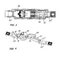
Fig. 3 eine Aufsicht auf die Schaltvorrichtung, -
Fig. 4 eine perspektivische Ansicht, -
Fig. 5 eine Darstellung des zweiarmigen Schaltstücks, -
Fig. 6 die Darstellung des Hebelarms in der Öffnungsbewegung, -
Fig. 7A und 7B perspektivische Ansicht und Seitenansicht des Magnetkörpers und -
Fig. 8 eine Darstellung des Schirmblechs. - Unter Bezugnahme auf die Figuren wird ein Niederspannungs-Lasttrennschalter dargestellt. Die Figuren zeigen beispielhaft eine Schaltvorrichtung mit einem Isolierstoffgehäuse 2. Das Isolierstoffgehäuse weist eine in einem Lager um eine feststehende Querachse drehbare Schaltwelle 90 auf, wobei die Querachse senkrecht zu Längsrichtung jedes Pols steht. Der Pol umfasst einen mit einer ersten Stromanschlussschiene 20' verbundenen Festkontakt 9'
- Der Kontakthebel 80 ist um 180° drehsymmetrisch ausgebildet und hat zwei sich gegenüberliegende Hebelarme 81, 82, welche sich entlang der Längsachse des Pols erstrecken und die Schaltwelle 90 durchdringen.
- Das bewegliche Kontaktstück 9" am ersten Hebelarm 81 des Kontakthebels 80 tritt mit dem ihm gegenüberstehenden festen Kontaktstück 9' in Schaltberührung. Am zweiten Hebelarm 82 des Kontakthebels 80 ist ein (schematisch gezeichneter) flexibler Leiter (Anschlusslitze) 22 fest verbunden. Die Anschlusslitze 22 führt leitend zu der zweiten Stromanschlussschiene 20" und hat dort ihre zweite Befestigungsstelle 22" (Lötstelle).
- Im Innern der Schaltwelle 90 sind zwei Kontaktkraftfedern 10', 10" angebracht, die auf den Kontakthebel 80 einwirken und einen festgelegten Kontaktdruck des Kontaktstücks 9" gewährleisten, wobei eines der Ende jeder Kontaktkraftfeder 10', 10" mit einem Mitnehmerelement der Schaltwelle zusammenwirkt und das andere Ende an einer Nase 84, bzw. durch die Nase gebildete Nut am Kontakthebel abgestützt wird. Die Angriffspunkte stehen sich diametral gegenüber.
- Ein für die Erfindung wesentliches Merkmal ist die Ausbildung zweier Kammern im Isolierstoffgehäuse. In der ersten Kammer (Löschkammer 40), in der sich der erste Hebelarm 81 bewegt, ist die für solche Schalter übliche Löscheinrichtung 42 untergebracht; in der zweiten Kammer - hier im Text als Anschlusskammer 50 bezeichnet - ist der zweite Hebelarm 82 beweglich angeordnet. Die Anschlusskammer 50 bietet Platz für die Bewegung des zweiten Hebelarms einschließlich des an ihm befestigten flexiblen Leiters 22. In der Anschlusskammer ist der Magnetkörper 30 angeordnet, der als das elektromagnetisch wirkende Kontaktkraftverstärkungsmittel dient.
- Ergänzend zu der aus einem Paket von Blechen bestehenden Löscheinrichtung 42 kann in der Löschkammer 40 in Nachbarschaft der Öffnungsstrecke des Kontakts ein lichtbogenlöschendes Material angeordnet sein. Dieses Material soll lichtbogenlöschende Gase freisetzen. Solche Materialen sind dem Fachmann bekannt. Sie bestehen in der Regel aus Kunststoff, dessen Beimengungen bei Erwärmung durch den Lichtbogen Gase ausscheiden. Das Material kann in Form mindestens eines plattenförmigen Einsatzes zu beiden Seiten der Öffnungsstrecke (Weg des Kontaktstücks 9") im Isolierstoffgehäuse formschlüssig eingebracht sein. Da die Öffnungsstrecke in der vorliegenden Ausführungsform relativ kurz ist, unterstützt das gasfreisetzende Material das Erlöschen eines Lichtbogens. Das Material kann modular in Form zweier Plättchen ausgebildet sein, die in Führungsnuten an der Gehäuseinnenwand einschiebbar sind.
- In den
Figuren 2 bis 4 sind neben anderen Einzelheiten die Anschlussschienen 20' und 20" erkennbar. Die Anschlussschienen sind vorzugsweise im Gerätegehäuse im Spritzgussverfahren integriert eingebettet. Als Besonderheit für die Lichtbogenlenkung ist in der Anschlussschiene 20' im Stromlauf direkt vor dem Festkontakt 9 ' eine Bohrung 24 eingebracht, in der ein Einsatzkörper (Niet) aus ferromagnetischem Material eingelegt ist. Durch die Bohrung wird die Strombahn vor dem Festkontakt aufgespreizt und der ferromagnetische Niet verändert die Struktur des Magnetfelds in der unmittelbaren Nähe des Schaltkontakts. Dabei wird die Bewegung eines sich ausbildenden Lichtbogens zur Löscheinrichtung hin bzw. in diese hinein gefördert. - In den
Fig. 7A (perspektivische Ansicht) undFig. 7B (Seitenansicht) ist der Magnetkörper 30 dargestellt. Der Magnetkörper 30 ist beispielsweise magnetisierbarer Stahl. Er ist im oberen Bereich der Anschlusskammer 50 über Schrauben 38, die durch Befestigungsbohrungen 39 greifen, befestigt. Der Magnetkörper hat die Form eines nach unten offenen Magnetjochs. Wobei im Grund des Magnetjochs ein als Befestigungsfläche 31 (Trogboden) dienender Querschenkel liegt. Am Trogboden sind rechts und links nach unten gerichtete Trogseitenflächen 32 ausgebildet. Der Trogboden öffnet sich im zum Kontakthebel gerichteten Bereich trapezförmig, da er dort die Anschlusslitze übergreift, die eine größere Breite einnimmt als der zweite Kontaktarm. - Die Schmalseite des Trapezes liegt kontakthebelseitig und die Breitseite des Trapezes liegt kontakthebelfern. Im vom Kontakthebel entfernten Bereich ist der Trogboden rechteckig ausgebildet. Die Trogseitenflächen übergreifen den zweiten Hebelarm und die Befestigungsstelle (Lötstelle) 22" des flexiblen Leiters in der Schliess-Stellung der Schaltanordnung. Das trogförmige Magnetjoch wird vorzugsweise möglichst groß ausgebildet, um eine möglichst große magnetische Durchflutung zu erzielen. Dies lässt sich einfach erreichen, weil die räumlichen Möglichkeiten der Anschlusskammer gut ausnutzbar sind.
- Die Trogseitenflächen 32 können auch noch einen Großteil des flexiblen Leiters übergreifen. Sie haben im Bereich der Überdeckung mit dem zweiten Kontaktarm einen ersten Bereich /, in dem sich die Seitenflanken 32a in Richtung auf die Anschlusslitze 22 erweitern. Die Aufsicht von unten auf den Magnetkörper 30 zeigt auch die
Fig. 3 . Die Mitte des Bereichs / entspricht etwa der Mitte der Position der Befestigungsstelle 22" des flexiblen Leiters am Hebelarm 81. Der Bereich / der Trogseitenflächen 32 bildet eine ansteigende Seitenflanke 32a und geht in einen Bereich II über. Dieser Bereich II - hier als Rückenflanke 32b bezeichnet - hat etwa dieselbe Länge wie die größte Länge der Seitenflanke 32a. Der Bereich II übergreift ein Stück der freien Anschlusslitze und wirkt als Abschirmung zwischen den Magnetfeldem der Anschlusslitzen benachbarter Pole. - Der Trogboden 31 des Magnetkörpers ist in Richtung zur Stromanschlussschiene um einen Bereich III verlängert - hier als Verlängerungsbereich 36 bezeichnet. An dem Bereich III sind keine Seitenflanken vorhanden. Mit dem Verlängerungsbereich wird bewirkt, dass die anziehende Kraft des Magnetjochs auch auf die Anschlusslitze wirksam werden kann.
- Über die Lebensdauer der Schaltvorrichtung arbeiten sich die Kontakte ab und der Durchhub ändert sich. Damit ändert sich auch die Lage des zweiten Schaltarms im Magnetkörper und die effektive magnetische Kraftverstärkung in Abhängigkeit vom aktuellen Durchhub. Form (Länge, Schrägausbildung) und Lage der Seitenflanken 32a werden vorzugsweise so gewählt, dass über die Lebensdauer der Schaltvorrichtung die magnetische Kraftverstärkung ansteigt, um am möglichen Lebensdauerende den größtmöglichen Wert zu erreichen.
- Der Kontakthebel 80 ist in
Fig. 5 und 6 dargestellt. Er ist um 180° drehsymmetrisch um seine Drehachse ausgebildet. An ihm sind zwischen seinem Drehpunkt 7 und den Hebelarmenden Mitnehmerflächen 86, 87 angeordnet, die von dem Antrieb der Schaltvorrichtung (Schaltwellensegmente 92, 93) beaufschlagt werden. - Im Kontakthebel ist eine Achs-Aufnahmebohrung 120 in Form eines Langlochs ausgebildet. Der Durchmesser D hat eine möglichst kleine Toleranz. Die Längsachse des Langlochs liegt auf einem Kreis mit dem Mittelpunkt M, so dass der Winkel W 90° beträgt.
- Wie in
Fig. 5 dargestellt ist die Längsachse des Langlochs 120 um einen Betrag E von 300 µm +/- 50 µm größer ist als die Querachse D des Langlochs. Die Hebelarm-Beziehung ist schematisch inFIG. 6 eingezeichnet. - Beim Schließen des Kontakts nach der ersten Kontaktgabe wird das Langloch an die Achse des Schaltwellensegments 92,93 angelegt; der Kontakthebel liegt außermittig. Bei der Öffnungsbewegung des Schaltwellensegments trifft dieses auf die Mitnehmerfläche 87 auf den außermittig liegenden Kontakthebel und leitet eine Kraftwirkung in die Verschweißzone bei M ein, bis das Schaltwellensegment am gegenüberliegenden Anschlag auftrifft und den Kontakt anhebt. Es ist ein axiales Spiel E möglich, welches die Veränderung der Hebelarm-Beziehung bewirkt. Der Angriff der öffnenden Kräfte oder Drehmomente des Antriebs der Schaltvorrichtung (Schaltwellensegmente 92,93) verändert in eine solche Angriffsposition, dass der lange Hebelarm H an der Mitnehmerfläche 87 wirksam wird und das öffnende Drehmoment deutlich vergrößert ist. Ein Angriff über die Mitnehmerflächefläche 86 findet nachrangig statt, vorrangig entsteht ein Drehmoment mit dem Hebelarm H Schaltwellensegment 92 auf die Mitnehmerfläche 87. Mit der durch den vergrößerte Hebelarm bewirkte Winkelbewegung entsteht eine höhere Kraft, die insbesondere das Trennen verschweißter Kontakte ermöglicht.
- An Lage und Form des Langlochs ist wesentlich, dass eine schräge Anstellung des Langlochs gegenüber der Längsachse des Kontakthebels vorhanden ist. Die damit bezweckte Wirkung wird unterstützt durch eine schräge Ausrichtung der Kontaktkraftfedern hinsichtlich ihrer longitudinalen Kraftwirkung, d.h. der Kraftlinie zwischen den Angriffspunkten der entsprechenden Kontaktkraftfeder an den zugehörigen Angriffspunkten, bzw. Hebelarmen des Kontaktarms und an der Schaltwelle bzw. dem Schaltwellensegment, gegenüber der Längsachse des Kontaktarms sowie dem Verlauf des Langlochs.
- So kann bei Verkleben der Kontaktstücke die Öffnungsbewegung (in Pfeilrichtung R) unterstützt werden durch eine erzwungene Verlagerung des Hebelarms bezüglich der Mitnehmerflächen auf dem Kontakthebel.
- Weiterhin ist in der Schaltwelle 90 im Bereich der Kontaktkraftfedern 10',10" ein Schirmblech 60 angeordnet, welches in
Fig. 8 gezeichnet ist. Das Schirmblech, dessen Lage in der Schaltwelle auch inFig. 1 zu erkennen ist, vermindert den Querschnitt für den Durchtritt von Lichtbogengasen aus der Kontaktkammer 40 in die Anschlusskammer 50. Damit lässt sich ein schnellerer Druckaufbau in der Kontaktkammer erzielen. Der Druckaufbau wirkt auf den entstehenden Lichtbogen und bläst ihn in Richtung Ausblasöffnung 44 der Kontaktkammer. Dies bewirkt vorteilhafterweise ein beschleunigtes Trennen des Lichtbogens vom Festkontaktstück 9'. Das Schirmblech 60 hat die Form eines Rechtecks. Im Inneren der Rechteckform ist ein Fenster 68 zum Durchgriff des Kontakthebels vorhanden. An der Schmalseite des Rechtecks ist ein Haken 64 ausgebildet zum Übergreifen über einen in der Schaltwelle 90 ausgebildeten Quersteg, der auch Angriffssteg für die Kontaktkraftfedern ist. Beim Zusammenbau der Schaltwelle mit Kontaktkraftfedern und Kontakthebel wird die Drehachse des Kontakthebels durch die Aufnahmen 67' im Schirmblech hindurch gefädelt. Das Schirmblech hat eine relative lockere Lage, um nicht die Beweglichkeit der Schaltwelle und des Kontakthebels einzuschränken. - Die Bezugszeichen sind in folgender Liste aufgeführt, auf die noch Bezug genommen werden soll, soweit sie nicht in der Beschreibung aufgeführt sind.
- 2
- Isolierstoffgehäuse
- 7
- Drehachse (Querachse)
- 9'
- Festkontaktstück
- 9"
- Kontaktstück am Kontakthebel
- 10' 10"
- Kontaktkraftfedern
- 20' 20"
- Anschlussschienen
- 22
- Litze
- 22' 22"
- Befestigungsstellen der Litze
- 24
- Bohrung/Niet in Anschlussschiene 20'
- 30
- magnetisierbarer Körper (Magnetjoch)
- I II III
- drei Bereiche des Körpers
- 31
- Befestigungsfläche (Querschenkel)
- 32
- Trogseitenflächen
- 32a
- Vorderflanke
- 32b
- Rückenflanke
- 36
- Verlängerungsbereich
- 38
- Befestigungsschrauben
- 39
- Befestigungsbohrungen
- 40
- Kontaktkammer (Löschkammer)
- 42
- Löscheinrichtung
- 44
- Ausblasöffnung
- 50
- Anschlusskammer
- 60
- Schirmblech
- 64
- Haken
- 67'
- Achsaufnahmen
- 68
- Fenster (Durchgriff für Kontakthebel)
- 80
- (zweiarmiger) Kontakthebel einfachunterbrechend
- 81, 82
- Hebelarme
- 84, 85
- Befestigungsnasen
- 86, 87
- Mitnehmerflächen
- E
- axiales Spiel
- W
- Winkel
- D
- Durchmesser Langloch
- R
- öffnende Drehrichtung
- H
- Hebelarm
- M
- Mitte Festkontakt (Verschweißungsstelle)
- 90
- Schaltwelle
- 92, 93
- Schaltwellensegmente (Mitnehmer)
- 120
- Langloch
Claims (12)
- Schaltvorrichtung für einen mehrpoligen Niederspannungs-Lasttrennschalter mit einem Isolierstoffgehäuse (2), in dem zwei Kammern ausgebildet sind, von denen eine erste Kammer als Löschkammer (40) und eine zweite Kammer mit vergleichbarem Volumen als Anschlusskammer (50) fungiert, weiterhin umfasst die Schaltvorrichtung einen einfach unterbrechenden, in einem Lager und in einer Schaltwelle (90)
gelagerten beweglichen Drehkontakt, wobei der Drehkontakt als zweiarmiger Hebel (80) ausgebildet ist, dessen erster Hebelarm (81) ein Kontaktstück (9') trägt, welches mit einem Festkontakt (9") an einer ersten Stromanschlussschiene (20') mit Unterstützung von Kontaktkraftfedern (10', 10") in Schaltberührung kommt, und der zweite Hebelarm (82) des Drehkontakts mit einem flexiblen Leiter (22) an einer Befestigungsstelle (22') verbunden ist, der in leitender Verbindung mit einer zweiten Stromanschlussschiene (20") steht,
dadurch gekennzeichnet, dass
in der Anschlusskammer (50) ein elektromagnetisch wirkendes Kontaktkraftverstärkungsmittel (30) angeordnet ist, welches in Schließ-Stellung der Kontaktstücke den zweiten Hebelarm (82) übergreift,
wobei das Kontaktkraftverstärkungsmittel (30) ebenfalls Teile des flexiblen Leiters (22) übergreift,
und wobei in der Schaltwelle (90) ein Schirmblech (60) vorhanden ist, welches den Querschnitt für den Durchtritt von Lichtbogengasen aus der Kontaktkammer (40) in die Anschlusskammer (50) vermindert. - Schaltvorrichtung nach Anspruch 1, dadurch gekennzeichnet, dass das Kontaktkraftverstärkungsmittel (30) als trogförmiges magnetisierbares Materialstück ausgebildet ist mit Lage des Trogbodens (31) parallel zum zweiten Hebelarm (82).
- Schaltvorrichtung nach vorhergehendem Anspruch, dadurch gekennzeichnet, dass das Kontaktkraftverstärkungsmittel (30) im oberen oder unteren Bereich der Anschlusskammer (50) befestigt ist, und mit nach zum zweiten Hebelarm (82) gerichteten Trogseitenflächen (32) den zweiten Hebelarm, die Befestigungsstelle (22') des flexiblen Leiters (22) am zweiten Hebelarm (82) und gegebenenfalls Teile des flexiblen Leiters (22) übergreift.
- Schaltvorrichtung nach Anspruch 3, dadurch gekennzeichnet, dass die Trogseitenflächen (32) im Bereich der Überdeckung mit dem zweiten Hebelarm (82) je eine Seitenflanke (32a) aufweisen, die ihren Ansatz hat am Ort des Endes des zweiten Hebelarms (82) und zum Drehpunkt des zweiten Hebelarms (82) hin ansteigt.
- Schaltvorrichtung nach einem der Ansprüche 3 oder 4, dadurch gekennzeichnet, dass jeweils im Bereich der Überdeckung mit dem flexiblen Leiter (22) die Trogseitenflächen (32) eine Rückenflanke (32b) aufweisen und der Trogboden eine Verlängerungsnase (III) aufweist.
- Schaltvorrichtung nach einem der vorhergehenden Ansprüche, dadurch gekennzeichnet, dass das Kontaktkraftverstärkungsmittel (30) mit möglichst grossem magnetischen Durchflutungsquerschnitt ausgebildet ist.
- Schaltvorrichtung nach einem der vorhergehenden Ansprüche, dadurch gekennzeichnet, dass der Kontakthebel (80) mit Ausnahme der Hebelarmlängen um 180° drehsymmetrisch ausgebildet ist.
- Schaltvorrichtung nach vorhergehendem Anspruch, dadurch gekennzeichnet, dass am Kontakthebel (80) zwischen seinem Drehpunkt (7) und den Hebelarmenden je eine Mitnehmerfläche (86, 87 angeordnet ist, die von dem Antrieb (92, 93) der Schaltvorrichtung beaufschlagbar ist.
- Schaltvorrichtung nach vorhergehendem Anspruch, dadurch gekennzeichnet, dass in dem Kontakthebel (80) eine Achs-Aufnahmebohrung (120) in Form eines Langlochs ausgebildet ist, dessen Längsachse auf einem Kreis liegt, dessen Mittelpunkt ( M ) in der Mitte der Berührungsflächen der Schaltkontaktstücke (9', 9") liegt.
- Schaltvorrichtung nach vorhergehendem Anspruch, dadurch gekennzeichnet, dass die Längsachse des Langlochs (120) um einen Betrag (E) von 300 µm +/- 50 µm grösser ist als die Querachse (D) des Langlochs.
- Schaltvorrichtung nach einem der vorhergehenden Ansprüche, dadurch gekennzeichnet, dass das Schirmblech (60) in Form eines Rechtecks ausgebildet ist mit einem im Inneren vorhandenen Fenster (68) zum Durchgriff des Kontakthebels und mit einem an der Schmalseite des Rechtecks ausgebildeten Haken (64) zum Übergreifen über einen in der Schaltwelle (90) ausgebildeten Quersteg.
- Schaltvorrichtung nach einem der vorhergehenden Ansprüche, dadurch gekennzeichnet, dass in der Löschkammer (40) in Nachbarschaft der Öffnungsstrecke des Kontakts (9', 9") ein Material angeordnet ist, welches lichtbogenlöschendes Gas freisetzt.
Applications Claiming Priority (2)
| Application Number | Priority Date | Filing Date | Title |
|---|---|---|---|
| DE10347148 | 2003-10-10 | ||
| DE2003147148 DE10347148B4 (de) | 2003-10-10 | 2003-10-10 | Schaltvorrichtung mit einfach unterbrechendem Drehkontakt |
Publications (2)
| Publication Number | Publication Date |
|---|---|
| EP1523020A1 EP1523020A1 (de) | 2005-04-13 |
| EP1523020B1 true EP1523020B1 (de) | 2015-08-05 |
Family
ID=34306356
Family Applications (1)
| Application Number | Title | Priority Date | Filing Date |
|---|---|---|---|
| EP04024128.3A Expired - Lifetime EP1523020B1 (de) | 2003-10-10 | 2004-10-09 | Schaltvorrichtung mit einfach unterbrechendem Drehkontakt |
Country Status (2)
| Country | Link |
|---|---|
| EP (1) | EP1523020B1 (de) |
| DE (1) | DE10347148B4 (de) |
Families Citing this family (10)
| Publication number | Priority date | Publication date | Assignee | Title |
|---|---|---|---|---|
| DE102006050767B3 (de) * | 2006-10-27 | 2008-05-29 | Moeller Gmbh | Stromzuführung für einen beweglichen Kontaktarm |
| DE102007048748A1 (de) * | 2007-10-08 | 2009-04-09 | Siemens Ag | Kontakthebel |
| DE102008037967A1 (de) * | 2008-08-13 | 2010-02-18 | Siemens Aktiengesellschaft | Drehkontaktsystem mit Toleranzausgleich für ein Schaltgerät sowie Schaltgeräte mit einem derartigen Drehkontaktsystem |
| DE102008039187B4 (de) | 2008-08-20 | 2019-06-19 | Siemens Aktiengesellschaft | Leistungsschalter, insbesondere für Niederspannungen |
| DE102008050755A1 (de) | 2008-10-07 | 2010-04-08 | Siemens Aktiengesellschaft | Elektrisches Gerät mit einem elektrischen Anschluss |
| DE102010015286A1 (de) | 2010-04-13 | 2011-10-13 | Siemens Aktiengesellschaft | Schalter, insbesondere Lasttrennschalter |
| EP2416332A1 (de) | 2010-08-06 | 2012-02-08 | Eaton Industries GmbH | Schaltvorrichtung für ein elektrisches Niederspannungsschaltgerät |
| EP2587508A1 (de) * | 2011-10-25 | 2013-05-01 | Eaton Industries GmbH | Leistungsschutzschalter |
| DE112016002449A5 (de) | 2015-06-01 | 2018-02-22 | Eaton Electrical Ip Gmbh & Co. Kg | Schutzschalter mit magnetisch unterstützter Öffnung |
| CN108987208B (zh) * | 2017-06-05 | 2024-04-02 | 周思雨 | 一种微型断路器及其灭弧装置 |
Family Cites Families (7)
| Publication number | Priority date | Publication date | Assignee | Title |
|---|---|---|---|---|
| US1918232A (en) | 1932-07-26 | 1933-07-11 | Westinghouse Electric & Mfg Co | Circuit interrupter |
| NL164631C (nl) * | 1950-11-05 | Delmag Maschinenfabrik | Dieselheiblok. | |
| DE1929091U (de) | 1965-08-05 | 1965-12-16 | Siemens Ag | Einrichtung zur kontaktdruckverstaerkung bei selbstschaltern. |
| US4078219A (en) * | 1976-02-12 | 1978-03-07 | Westinghouse Electric Corporation | Overcurrent latch for magnetic contactor |
| DE2615726A1 (de) * | 1976-04-10 | 1977-10-27 | Bbc Brown Boveri & Cie | Kontaktanordnung |
| WO2003015114A1 (fr) * | 2001-08-02 | 2003-02-20 | Mitsubishi Denki Kabushiki Kaisha | Disjoncteur a air |
| ITMI20012586A1 (it) * | 2001-12-10 | 2003-06-10 | Abb Service Srl | Polo elettrico per un interruttore di potenza di bassa tensione, e relativo interruttore |
-
2003
- 2003-10-10 DE DE2003147148 patent/DE10347148B4/de not_active Expired - Fee Related
-
2004
- 2004-10-09 EP EP04024128.3A patent/EP1523020B1/de not_active Expired - Lifetime
Also Published As
| Publication number | Publication date |
|---|---|
| DE10347148B4 (de) | 2006-01-19 |
| DE10347148A1 (de) | 2005-05-12 |
| EP1523020A1 (de) | 2005-04-13 |
Similar Documents
| Publication | Publication Date | Title |
|---|---|---|
| EP2030216B1 (de) | Schutzschalter | |
| DE4104533C2 (de) | Elektrischer Schalter | |
| EP0174904B1 (de) | Kontaktanordnung für Niederspannungs-Leistungsschalter mit einem zweiarmigen Kontakthebel | |
| DE69302610T2 (de) | Kontakt für Lastschalter mit gegossenem Gehäuse | |
| DE3535567C2 (de) | ||
| DE68911752T2 (de) | Fernbetätigbarer Schalter. | |
| DE69937107T2 (de) | Strombegrenzer und schalter mit strombegrenzungsfunktion | |
| DE69328444T2 (de) | Schalter | |
| DE3528196C2 (de) | ||
| EP0563774A2 (de) | Fernsteuerbarer Schutzschalter | |
| DE3323474C2 (de) | Stromkreisunterbrecher | |
| DE10347148B4 (de) | Schaltvorrichtung mit einfach unterbrechendem Drehkontakt | |
| DE19540972B4 (de) | Strombegrenzendes Kontaktsystem mit Doppeltunterbrechung für Niederspannungs-Schutzschalter | |
| DE19915397A1 (de) | Leitungsschutzschalter | |
| DE2756741C2 (de) | Elektrisches Schaltgerät mit elektromagnetischer Kontaktdruckerhöhung | |
| EP2030211A1 (de) | Leistungsschalter oder leitungsschutzschalter | |
| DE636718C (de) | Elektromagnetischer UEberstromschalter | |
| DE10144440C1 (de) | Schaltkontaktanordnung mit einer Einrichtung zur Verstärkung einer zwischen Schaltkontakten wirkenden Kontaktkraft | |
| DE69508482T2 (de) | Elektrischer Lastschalter mit elektromagnetischem Betätiger für Hochstrom | |
| EP3770934B1 (de) | Schaltgerät und spannungsbegrenzungseinrichtung mit einem schaltgerät | |
| EP1473752A1 (de) | Elektromagnetischer Auslöser | |
| DE1588146A1 (de) | Druckknopfbetaetigter UEberstromschalter | |
| EP1096528B1 (de) | Elektrisches Schutzschaltgerät | |
| DE69834159T2 (de) | Schutzschalter mit elektromagnetischen Auslöser mit Antrieb für einen beweglichen und gabelförmigen Kontakt | |
| EP1096529B1 (de) | Elektrisches Schutzschaltgerät |
Legal Events
| Date | Code | Title | Description |
|---|---|---|---|
| PUAI | Public reference made under article 153(3) epc to a published international application that has entered the european phase |
Free format text: ORIGINAL CODE: 0009012 |
|
| AK | Designated contracting states |
Kind code of ref document: A1 Designated state(s): AT BE BG CH CY CZ DE DK EE ES FI FR GB GR HU IE IT LI LU MC NL PL PT RO SE SI SK TR |
|
| AX | Request for extension of the european patent |
Extension state: AL HR LT LV MK |
|
| AKX | Designation fees paid | ||
| 17P | Request for examination filed |
Effective date: 20051117 |
|
| RBV | Designated contracting states (corrected) |
Designated state(s): AT BE BG CH CY CZ DE DK EE ES FI FR GB GR HU IE IT LI LU MC NL PL PT RO SE SI SK TR |
|
| REG | Reference to a national code |
Ref country code: DE Ref legal event code: 8566 |
|
| RAP1 | Party data changed (applicant data changed or rights of an application transferred) |
Owner name: EATON INDUSTIES GMBH |
|
| RAP1 | Party data changed (applicant data changed or rights of an application transferred) |
Owner name: EATON INDUSTRIES GMBH |
|
| 17Q | First examination report despatched |
Effective date: 20120210 |
|
| RAP1 | Party data changed (applicant data changed or rights of an application transferred) |
Owner name: EATON ELECTRICAL IP GMBH & CO. KG |
|
| GRAP | Despatch of communication of intention to grant a patent |
Free format text: ORIGINAL CODE: EPIDOSNIGR1 |
|
| RIC1 | Information provided on ipc code assigned before grant |
Ipc: H01H 9/30 20060101ALN20150204BHEP Ipc: H01H 1/58 20060101ALI20150204BHEP Ipc: H01H 1/20 20060101ALN20150204BHEP Ipc: H01H 9/34 20060101ALN20150204BHEP Ipc: H01H 1/54 20060101AFI20150204BHEP |
|
| INTG | Intention to grant announced |
Effective date: 20150303 |
|
| GRAS | Grant fee paid |
Free format text: ORIGINAL CODE: EPIDOSNIGR3 |
|
| GRAA | (expected) grant |
Free format text: ORIGINAL CODE: 0009210 |
|
| AK | Designated contracting states |
Kind code of ref document: B1 Designated state(s): AT BE BG CH CY CZ DE DK EE ES FI FR GB GR HU IE IT LI LU MC NL PL PT RO SE SI SK TR |
|
| REG | Reference to a national code |
Ref country code: GB Ref legal event code: FG4D Free format text: NOT ENGLISH |
|
| REG | Reference to a national code |
Ref country code: CH Ref legal event code: EP |
|
| REG | Reference to a national code |
Ref country code: AT Ref legal event code: REF Ref document number: 741111 Country of ref document: AT Kind code of ref document: T Effective date: 20150815 |
|
| REG | Reference to a national code |
Ref country code: IE Ref legal event code: FG4D Free format text: LANGUAGE OF EP DOCUMENT: GERMAN |
|
| REG | Reference to a national code |
Ref country code: DE Ref legal event code: R096 Ref document number: 502004014983 Country of ref document: DE |
|
| REG | Reference to a national code |
Ref country code: FR Ref legal event code: PLFP Year of fee payment: 12 |
|
| REG | Reference to a national code |
Ref country code: RO Ref legal event code: EPE |
|
| REG | Reference to a national code |
Ref country code: NL Ref legal event code: MP Effective date: 20150805 |
|
| PG25 | Lapsed in a contracting state [announced via postgrant information from national office to epo] |
Ref country code: FI Free format text: LAPSE BECAUSE OF FAILURE TO SUBMIT A TRANSLATION OF THE DESCRIPTION OR TO PAY THE FEE WITHIN THE PRESCRIBED TIME-LIMIT Effective date: 20150805 Ref country code: GR Free format text: LAPSE BECAUSE OF FAILURE TO SUBMIT A TRANSLATION OF THE DESCRIPTION OR TO PAY THE FEE WITHIN THE PRESCRIBED TIME-LIMIT Effective date: 20151106 |
|
| PG25 | Lapsed in a contracting state [announced via postgrant information from national office to epo] |
Ref country code: PT Free format text: LAPSE BECAUSE OF FAILURE TO SUBMIT A TRANSLATION OF THE DESCRIPTION OR TO PAY THE FEE WITHIN THE PRESCRIBED TIME-LIMIT Effective date: 20151207 Ref country code: ES Free format text: LAPSE BECAUSE OF FAILURE TO SUBMIT A TRANSLATION OF THE DESCRIPTION OR TO PAY THE FEE WITHIN THE PRESCRIBED TIME-LIMIT Effective date: 20150805 Ref country code: SE Free format text: LAPSE BECAUSE OF FAILURE TO SUBMIT A TRANSLATION OF THE DESCRIPTION OR TO PAY THE FEE WITHIN THE PRESCRIBED TIME-LIMIT Effective date: 20150805 Ref country code: PL Free format text: LAPSE BECAUSE OF FAILURE TO SUBMIT A TRANSLATION OF THE DESCRIPTION OR TO PAY THE FEE WITHIN THE PRESCRIBED TIME-LIMIT Effective date: 20150805 |
|
| PGFP | Annual fee paid to national office [announced via postgrant information from national office to epo] |
Ref country code: FR Payment date: 20151027 Year of fee payment: 12 Ref country code: CZ Payment date: 20151005 Year of fee payment: 12 Ref country code: RO Payment date: 20151001 Year of fee payment: 12 |
|
| PG25 | Lapsed in a contracting state [announced via postgrant information from national office to epo] |
Ref country code: NL Free format text: LAPSE BECAUSE OF FAILURE TO SUBMIT A TRANSLATION OF THE DESCRIPTION OR TO PAY THE FEE WITHIN THE PRESCRIBED TIME-LIMIT Effective date: 20150805 |
|
| PG25 | Lapsed in a contracting state [announced via postgrant information from national office to epo] |
Ref country code: SK Free format text: LAPSE BECAUSE OF FAILURE TO SUBMIT A TRANSLATION OF THE DESCRIPTION OR TO PAY THE FEE WITHIN THE PRESCRIBED TIME-LIMIT Effective date: 20150805 Ref country code: DK Free format text: LAPSE BECAUSE OF FAILURE TO SUBMIT A TRANSLATION OF THE DESCRIPTION OR TO PAY THE FEE WITHIN THE PRESCRIBED TIME-LIMIT Effective date: 20150805 Ref country code: EE Free format text: LAPSE BECAUSE OF FAILURE TO SUBMIT A TRANSLATION OF THE DESCRIPTION OR TO PAY THE FEE WITHIN THE PRESCRIBED TIME-LIMIT Effective date: 20150805 |
|
| PGFP | Annual fee paid to national office [announced via postgrant information from national office to epo] |
Ref country code: IT Payment date: 20150930 Year of fee payment: 12 |
|
| REG | Reference to a national code |
Ref country code: DE Ref legal event code: R097 Ref document number: 502004014983 Country of ref document: DE |
|
| PG25 | Lapsed in a contracting state [announced via postgrant information from national office to epo] |
Ref country code: LU Free format text: LAPSE BECAUSE OF FAILURE TO SUBMIT A TRANSLATION OF THE DESCRIPTION OR TO PAY THE FEE WITHIN THE PRESCRIBED TIME-LIMIT Effective date: 20151009 |
|
| REG | Reference to a national code |
Ref country code: CH Ref legal event code: PL |
|
| PLBE | No opposition filed within time limit |
Free format text: ORIGINAL CODE: 0009261 |
|
| STAA | Information on the status of an ep patent application or granted ep patent |
Free format text: STATUS: NO OPPOSITION FILED WITHIN TIME LIMIT |
|
| PG25 | Lapsed in a contracting state [announced via postgrant information from national office to epo] |
Ref country code: MC Free format text: LAPSE BECAUSE OF FAILURE TO SUBMIT A TRANSLATION OF THE DESCRIPTION OR TO PAY THE FEE WITHIN THE PRESCRIBED TIME-LIMIT Effective date: 20150805 |
|
| 26N | No opposition filed |
Effective date: 20160509 |
|
| GBPC | Gb: european patent ceased through non-payment of renewal fee |
Effective date: 20151105 |
|
| REG | Reference to a national code |
Ref country code: IE Ref legal event code: MM4A |
|
| PG25 | Lapsed in a contracting state [announced via postgrant information from national office to epo] |
Ref country code: CH Free format text: LAPSE BECAUSE OF NON-PAYMENT OF DUE FEES Effective date: 20151031 Ref country code: LI Free format text: LAPSE BECAUSE OF NON-PAYMENT OF DUE FEES Effective date: 20151031 |
|
| PG25 | Lapsed in a contracting state [announced via postgrant information from national office to epo] |
Ref country code: SI Free format text: LAPSE BECAUSE OF FAILURE TO SUBMIT A TRANSLATION OF THE DESCRIPTION OR TO PAY THE FEE WITHIN THE PRESCRIBED TIME-LIMIT Effective date: 20150805 |
|
| PG25 | Lapsed in a contracting state [announced via postgrant information from national office to epo] |
Ref country code: IE Free format text: LAPSE BECAUSE OF NON-PAYMENT OF DUE FEES Effective date: 20151009 Ref country code: GB Free format text: LAPSE BECAUSE OF NON-PAYMENT OF DUE FEES Effective date: 20151105 |
|
| REG | Reference to a national code |
Ref country code: AT Ref legal event code: MM01 Ref document number: 741111 Country of ref document: AT Kind code of ref document: T Effective date: 20151009 |
|
| PG25 | Lapsed in a contracting state [announced via postgrant information from national office to epo] |
Ref country code: AT Free format text: LAPSE BECAUSE OF NON-PAYMENT OF DUE FEES Effective date: 20151009 |
|
| PG25 | Lapsed in a contracting state [announced via postgrant information from national office to epo] |
Ref country code: CZ Free format text: LAPSE BECAUSE OF NON-PAYMENT OF DUE FEES Effective date: 20161009 Ref country code: HU Free format text: LAPSE BECAUSE OF FAILURE TO SUBMIT A TRANSLATION OF THE DESCRIPTION OR TO PAY THE FEE WITHIN THE PRESCRIBED TIME-LIMIT; INVALID AB INITIO Effective date: 20041009 Ref country code: BG Free format text: LAPSE BECAUSE OF FAILURE TO SUBMIT A TRANSLATION OF THE DESCRIPTION OR TO PAY THE FEE WITHIN THE PRESCRIBED TIME-LIMIT Effective date: 20150805 |
|
| PG25 | Lapsed in a contracting state [announced via postgrant information from national office to epo] |
Ref country code: CY Free format text: LAPSE BECAUSE OF FAILURE TO SUBMIT A TRANSLATION OF THE DESCRIPTION OR TO PAY THE FEE WITHIN THE PRESCRIBED TIME-LIMIT Effective date: 20150805 |
|
| REG | Reference to a national code |
Ref country code: FR Ref legal event code: ST Effective date: 20170630 |
|
| PG25 | Lapsed in a contracting state [announced via postgrant information from national office to epo] |
Ref country code: FR Free format text: LAPSE BECAUSE OF NON-PAYMENT OF DUE FEES Effective date: 20161102 Ref country code: BE Free format text: LAPSE BECAUSE OF NON-PAYMENT OF DUE FEES Effective date: 20151031 Ref country code: RO Free format text: LAPSE BECAUSE OF NON-PAYMENT OF DUE FEES Effective date: 20161009 |
|
| PG25 | Lapsed in a contracting state [announced via postgrant information from national office to epo] |
Ref country code: TR Free format text: LAPSE BECAUSE OF FAILURE TO SUBMIT A TRANSLATION OF THE DESCRIPTION OR TO PAY THE FEE WITHIN THE PRESCRIBED TIME-LIMIT Effective date: 20150805 |
|
| PG25 | Lapsed in a contracting state [announced via postgrant information from national office to epo] |
Ref country code: IT Free format text: LAPSE BECAUSE OF NON-PAYMENT OF DUE FEES Effective date: 20161009 |
|
| REG | Reference to a national code |
Ref country code: DE Ref legal event code: R081 Ref document number: 502004014983 Country of ref document: DE Owner name: EATON INTELLIGENT POWER LIMITED, IE Free format text: FORMER OWNER: EATON ELECTRICAL IP GMBH & CO. KG, 12529 SCHOENEFELD, DE |
|
| PGFP | Annual fee paid to national office [announced via postgrant information from national office to epo] |
Ref country code: DE Payment date: 20190918 Year of fee payment: 16 |
|
| REG | Reference to a national code |
Ref country code: DE Ref legal event code: R119 Ref document number: 502004014983 Country of ref document: DE |
|
| PG25 | Lapsed in a contracting state [announced via postgrant information from national office to epo] |
Ref country code: DE Free format text: LAPSE BECAUSE OF NON-PAYMENT OF DUE FEES Effective date: 20210501 |