EP1522803B1 - Constant differential pressure valve - Google Patents
Constant differential pressure valve Download PDFInfo
- Publication number
- EP1522803B1 EP1522803B1 EP04021619A EP04021619A EP1522803B1 EP 1522803 B1 EP1522803 B1 EP 1522803B1 EP 04021619 A EP04021619 A EP 04021619A EP 04021619 A EP04021619 A EP 04021619A EP 1522803 B1 EP1522803 B1 EP 1522803B1
- Authority
- EP
- European Patent Office
- Prior art keywords
- valve
- movable core
- pipe
- core
- differential pressure
- Prior art date
- Legal status (The legal status is an assumption and is not a legal conclusion. Google has not performed a legal analysis and makes no representation as to the accuracy of the status listed.)
- Expired - Lifetime
Links
- 238000005057 refrigeration Methods 0.000 claims description 12
- 239000007787 solid Substances 0.000 claims description 7
- 230000001276 controlling effect Effects 0.000 claims description 3
- 230000001105 regulatory effect Effects 0.000 claims description 2
- 230000033001 locomotion Effects 0.000 claims 2
- 239000003507 refrigerant Substances 0.000 description 23
- 238000011144 upstream manufacturing Methods 0.000 description 19
- 230000006837 decompression Effects 0.000 description 2
- 230000003247 decreasing effect Effects 0.000 description 2
- 230000002093 peripheral effect Effects 0.000 description 2
- 239000003208 petroleum Substances 0.000 description 2
- 230000007423 decrease Effects 0.000 description 1
- 230000001419 dependent effect Effects 0.000 description 1
- 238000010586 diagram Methods 0.000 description 1
- 239000007788 liquid Substances 0.000 description 1
- 238000004519 manufacturing process Methods 0.000 description 1
- XLYOFNOQVPJJNP-UHFFFAOYSA-N water Substances O XLYOFNOQVPJJNP-UHFFFAOYSA-N 0.000 description 1
Images


Classifications
-
- F—MECHANICAL ENGINEERING; LIGHTING; HEATING; WEAPONS; BLASTING
- F16—ENGINEERING ELEMENTS AND UNITS; GENERAL MEASURES FOR PRODUCING AND MAINTAINING EFFECTIVE FUNCTIONING OF MACHINES OR INSTALLATIONS; THERMAL INSULATION IN GENERAL
- F16K—VALVES; TAPS; COCKS; ACTUATING-FLOATS; DEVICES FOR VENTING OR AERATING
- F16K31/00—Actuating devices; Operating means; Releasing devices
- F16K31/02—Actuating devices; Operating means; Releasing devices electric; magnetic
- F16K31/06—Actuating devices; Operating means; Releasing devices electric; magnetic using a magnet, e.g. diaphragm valves, cutting off by means of a liquid
- F16K31/0644—One-way valve
- F16K31/0655—Lift valves
-
- F—MECHANICAL ENGINEERING; LIGHTING; HEATING; WEAPONS; BLASTING
- F16—ENGINEERING ELEMENTS AND UNITS; GENERAL MEASURES FOR PRODUCING AND MAINTAINING EFFECTIVE FUNCTIONING OF MACHINES OR INSTALLATIONS; THERMAL INSULATION IN GENERAL
- F16K—VALVES; TAPS; COCKS; ACTUATING-FLOATS; DEVICES FOR VENTING OR AERATING
- F16K31/00—Actuating devices; Operating means; Releasing devices
- F16K31/02—Actuating devices; Operating means; Releasing devices electric; magnetic
- F16K31/06—Actuating devices; Operating means; Releasing devices electric; magnetic using a magnet, e.g. diaphragm valves, cutting off by means of a liquid
- F16K31/0644—One-way valve
- F16K31/0651—One-way valve the fluid passing through the solenoid coil
-
- F—MECHANICAL ENGINEERING; LIGHTING; HEATING; WEAPONS; BLASTING
- F25—REFRIGERATION OR COOLING; COMBINED HEATING AND REFRIGERATION SYSTEMS; HEAT PUMP SYSTEMS; MANUFACTURE OR STORAGE OF ICE; LIQUEFACTION SOLIDIFICATION OF GASES
- F25B—REFRIGERATION MACHINES, PLANTS OR SYSTEMS; COMBINED HEATING AND REFRIGERATION SYSTEMS; HEAT PUMP SYSTEMS
- F25B41/00—Fluid-circulation arrangements
- F25B41/30—Expansion means; Dispositions thereof
- F25B41/31—Expansion valves
- F25B41/34—Expansion valves with the valve member being actuated by electric means, e.g. by piezoelectric actuators
- F25B41/345—Expansion valves with the valve member being actuated by electric means, e.g. by piezoelectric actuators by solenoids
-
- G—PHYSICS
- G05—CONTROLLING; REGULATING
- G05D—SYSTEMS FOR CONTROLLING OR REGULATING NON-ELECTRIC VARIABLES
- G05D16/00—Control of fluid pressure
- G05D16/028—Controlling a pressure difference
-
- G—PHYSICS
- G05—CONTROLLING; REGULATING
- G05D—SYSTEMS FOR CONTROLLING OR REGULATING NON-ELECTRIC VARIABLES
- G05D16/00—Control of fluid pressure
- G05D16/20—Control of fluid pressure characterised by the use of electric means
- G05D16/2006—Control of fluid pressure characterised by the use of electric means with direct action of electric energy on controlling means
- G05D16/2013—Control of fluid pressure characterised by the use of electric means with direct action of electric energy on controlling means using throttling means as controlling means
- G05D16/2022—Control of fluid pressure characterised by the use of electric means with direct action of electric energy on controlling means using throttling means as controlling means actuated by a proportional solenoid
-
- F—MECHANICAL ENGINEERING; LIGHTING; HEATING; WEAPONS; BLASTING
- F25—REFRIGERATION OR COOLING; COMBINED HEATING AND REFRIGERATION SYSTEMS; HEAT PUMP SYSTEMS; MANUFACTURE OR STORAGE OF ICE; LIQUEFACTION SOLIDIFICATION OF GASES
- F25B—REFRIGERATION MACHINES, PLANTS OR SYSTEMS; COMBINED HEATING AND REFRIGERATION SYSTEMS; HEAT PUMP SYSTEMS
- F25B2600/00—Control issues
- F25B2600/25—Control of valves
- F25B2600/2505—Fixed-differential control valves
-
- Y—GENERAL TAGGING OF NEW TECHNOLOGICAL DEVELOPMENTS; GENERAL TAGGING OF CROSS-SECTIONAL TECHNOLOGIES SPANNING OVER SEVERAL SECTIONS OF THE IPC; TECHNICAL SUBJECTS COVERED BY FORMER USPC CROSS-REFERENCE ART COLLECTIONS [XRACs] AND DIGESTS
- Y02—TECHNOLOGIES OR APPLICATIONS FOR MITIGATION OR ADAPTATION AGAINST CLIMATE CHANGE
- Y02B—CLIMATE CHANGE MITIGATION TECHNOLOGIES RELATED TO BUILDINGS, e.g. HOUSING, HOUSE APPLIANCES OR RELATED END-USER APPLICATIONS
- Y02B30/00—Energy efficient heating, ventilation or air conditioning [HVAC]
- Y02B30/70—Efficient control or regulation technologies, e.g. for control of refrigerant flow, motor or heating
Definitions
- the invention relates to a constant differential pressure valve according to the preamble of claim 1.
- a refrigeration cycle e.g. of an automotive air conditioner
- high-temperature, high-pressure gaseous refrigerant compressed by a compressor is condensed or cooled by a condenser or a gas cooler, and then is changed by a decompression device into low-temperature, low-pressure refrigerant, before it is evaporated by an evaporator.
- the evaporated refrigerant is separated into gas and liquid by an accumulator.
- the gaseous refrigerant is returned to the compressor.
- the decompression device ( JP-A-H11-316068 ) is a constant differential pressure valve for electrically controlling the differential pressure.
- a differential pressure control mechanism is integrated into a body block separate from piping of the refrigeration cycle. Separately connected pipes introduce the high-pressure refrigerant and deliver the decompressed refrigerant to the evaporator.
- An internal valve element is operated by supplying a predetermined electric current to a solenoid. The flow rate is controlled such that the differential pressure across the constant differential pressure valve is held constant.
- the arrangement of a separate body block and of the pipes increase the size of the entire constant differential pressure valve and occupies a large amount of precious mounting space.
- An internal refrigerant passage where internal structures of the differential pressure control mechanism, such as the valve element, are arranged, and a solenoid section are separately disposed in the body block. Further, it is necessary to perform complicated adjustment for arranging the respective pipes of refrigerant inlet and outlet passages and the internal refrigerant passage connecting the pipes, which increases the manufacturing costs.
- JP-A-04272589 discloses a constant differential pressure valve for regulating the amount of petroleum in a petroleum hot water feeder by generating a differential pressure corresponding to a current value of the current supplied to a solenoid coil.
- the movable core When the valve is closed the movable core is loaded by the inlet pressure on an effective pressure receiving area corresponding to the size of the surface at which a flexible valve element insert abuts on the valve seat in valve closing direction.
- the movable core is loaded in both moving directions by springs. Upstream of the movable core a second ball valve is provided.
- the solenoid has to be relatively strong, because for moving the movable core to the reference position the full force of the inlet pressure acting in valve closing direction has to be overcome.
- the mentioned “pipe” may, for example, be provided exclusively for the constant differential pressure valve itself, and is then connected to the piping of the refrigeration cycle by a joint or the like, or alternatively, is already a part of the piping of the refrigeration cycle.
- the mentioned "predetermined reference position” is a position at which the differential pressure is equal to the constant differential pressure set in advance, and means a position at which a balance of the internal refrigerant pressures and urging forces applied to the movable core is achieved.
- the movable core In the constant differential pressure valve, the movable core is moved toward or away from the fixed core by energizing or de-energizing the solenoid coil. This produces valve-opening or valve-closing operations of the differential pressure control mechanism to correspondingly adjust the size of the internal passage cross-section. Refrigerant from upstream is decompressed by being expanded when flowing downstream via the fixed core and the movable core through the differential pressure control mechanism. The flow rate is controlled such that the differential pressure between respective pressures at the inlet and the outlet is equal to the constant differential pressure dependent on the value of the electric current supplied to the solenoid coil.
- the pipe forming the body does not only accommodate the internal structures, such as the differential pressure control mechanism, the fixed core, and the movable core, but also is a part of the piping of the refrigeration cycle.
- Part of the refrigerant introduced from upstream is also introduced via the communication hole into the inner space of the movable core.
- the inlet pressure and the pressure in the inner space become equal.
- a considerable part of the pressure force applied in valve opening direction to the valve portion and also to the movable core is cancelled by the inlet pressure also acting in valve closing direction in the inner space.
- Even if the cross-section of the valve seat is large, the valve can be controlled by a relatively weak solenoid and, furthermore, also the spring urging the movable core in valve closing direction can have a small spring force.
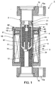
- a constant differential pressure valve 1 comprises a body formed by a hollow cylindrical pipe 2 having opposite open ends, a fixed core 3, a movable core 4, a solid shaft 5, a stopper 6, and a hollow cylindrical member 7, accommodated in the pipe 2, and a solenoid section 10 disposed on and surrounding the periphery of the pipe 2.
- Piping joints 70 of generally oval shape are attached to the opposite ends of the pipe 2. Each pipe has the diameter increased after the piping joint 70 is fitted on the pipe 2.
- the piping joint 2 has a through hole 70a for a bolt.
- piping joints identical to the piping joint 70 are fitted on pipes of the piping of the refrigeration cycle.
- Each pair of associated piping joints are connected via an O ring by a bolt through the aligned through holes and by tightening a nut, such that the pipe 2 is a part of a refrigerant passage.
- the fixed core 3 has a hollow cylindrical body with a circumferential peripheral fitting groove 31.
- the diameter of the upstream end of the fixed core 3 is increased by a predetermined amount to accommodate and fix the stopper 6.
- the fixed core 3 is fixed in the pipe 2 swaging the wall of the pipe 2 into the fitting groove 31.
- the movable core 4 has a bottomed hollow cylinder body. The bottom is located on the upstream side.
- the movable core 4 is disposed within the pipe 2 at a location upstream of the fixed core 3.
- a tapered valve portion 41 (the outer diameter progressively decreased upstream) protrudes from the upstream end of the movable core 4.
- a communication hole 43 extends axially through the valve portion 41, for introducing refrigerant into a bore part 42 within the movable core 4.
- the movable core 4 is axially movably guided on the solid shaft 5 which is rigidly secured in the pipe 2.
- the inner diameter of the downstream end of the movable core 4 is increased by a predetermined amount to form a chamber 44 accommodating a spring 81.
- a clearance passage 91 is provided between the movable core 4 and the inner wall of the pipe 2.
- the solid shaft 5 has a column-shaped body with an outer diameter approximately equal to the inner diameter of the bore part 42 of the movable core 4.
- the downstream end of the solid shaft 5 is fixed to the upstream end face of the stopper 6.
- the upstream end face of the solid shaft 5 and the inner wall of the movable core 4 at the bore part 42 define an inner space 92 communicating with the communication hole 43.
- the stopper 6 has a disk-shaped body and is press-fitted into a stepped portion 32 in the increased-diameter portion of the fixed core 3.
- the stopper 6 contains an axial slit 61 in one-side as a part of the refrigerant passage through the constant differential valve 1.
- the spring 81 (elastic member) between the stopper 6 and the downstream facing wall of the chamber 44 of the movable core 4 supports the movable core 4 by the fixed core 3 when the solenoid section 10 is de-energised.
- the hollow cylindrical member 7 is disposed in the pipe 2 at a location upstream of the movable core 4.
- the hollow cylindrical member 7 has a circumferential peripheral fitting groove 71 and is fixed in the pipe 2 by swaging the wall of the pipe 2 into the fitting groove 71.
- the rim of an opening of a fixed passage 95 in the hollow cylindrical member 7 forms a valve seat 72 for the valve portion 41 of the movable core 4.
- the solenoid section 10 has a generally hollow cylindrical shape, and contains a first bobbin 12 with a solenoid coil 11 wound around the outer periphery of the pipe 2. On the upstream end of the first bobbin 12, there is disposed a second bobbin 13 which cooperates with the first bobbin 12 to form a passage for lead wires to the terminals of the solenoid coil 11.
- the first and second bobbins 12, 13 are enclosed by a first yoke 14.
- the upstream end of the first yoke 14 is closed by a second yoke 15 to form, together with fixed core 3 and the movable core 4, a continuous magnetic circuit.
- Fig. 1 shows a state of the de-energised solenoid coil 11,
- Fig. 2 shows a state of the energized solenoid coil 11.
- Fig. 1 the movable core 4 is urged upstream by the spring 81.
- the valve portion 41 is seated on the valve seat 72 (fully-closed state).
- an electric current i is supplied to the solenoid coil 11.
- An electromagnetic force the magnitude of which corresponds to the value of the electric current i is generated attracting the movable core 4 toward the fixed core 3.
- the valve portion 41 moves away from the valve seat 72 into a position where the electromagnetic force and the load of the spring 81 are balanced, whereby a predetermined passage cross-section is formed between the valve portion 41 and the valve seat 72.
- High-pressure refrigerant introduced from upstream is adiabatically expanded through a refrigerant passage 93 between the valve portion 41 and the valve seat 72, and further flows downstream through the clearance passage 91 and the slit 61.
- part of the refrigerant introduced from upstream is also introduced via the communication hole 43 into the inner space 92.
- the inlet pressure and the pressure in the inner space 92 become equal.
- a part of the pressure applied to the valve portion 41 and hence to the movable core 4 is cancelled.
- the pressure at a refrigerant inlet 51 is P1
- the outlet pressure which has been reduced due to passage of the refrigerant through the refrigerant passage 93
- an effective pressure-receiving area of the valve portion 41 in a seated state i.e. the passage cross-section of the hollow cylindrical member 7
- the cross-sectional area of the inner space 92 is B
- the electromagnetic force generated by the current i is f(i)
- the load of the spring 81 in the upstream is fs.
- the parameters except the electromagnetic force f(i) are substantially fixed values, and therefore the differential pressure (P1 - P2) is held at a constant value proportional to the electric current i supplied to the solenoid coil 11.
- the abscissa represents the value of the electric current i
- the ordinate represents the differential pressure (P1 - P2).
- the valve portion 41 moves in valve-opening direction to increase the flow rate, and such that its effective pressure-receiving area is increased, thereby holding the differential pressure (P1 - P2) constant. If the refrigerant flow rate in the refrigeration cycle decreases upstream of the constant differential pressure valve 1 and lowers the inlet pressure P1, the valve portion 41 moves in valve-closing direction to reduce the flow rate and such that the effective pressure-receiving area is decreased, thereby holding the differential pressure (P1 - P2) constant.
- the differential pressure (P1 - P2) is always held at a constant value determined by the value of the electric current i.
Landscapes
- Engineering & Computer Science (AREA)
- Physics & Mathematics (AREA)
- General Engineering & Computer Science (AREA)
- Mechanical Engineering (AREA)
- Fluid Mechanics (AREA)
- Thermal Sciences (AREA)
- General Physics & Mathematics (AREA)
- Automation & Control Theory (AREA)
- Magnetically Actuated Valves (AREA)
Applications Claiming Priority (2)
| Application Number | Priority Date | Filing Date | Title |
|---|---|---|---|
| JP2003320508A JP4235515B2 (ja) | 2003-09-12 | 2003-09-12 | 定差圧弁 |
| JP2003320508 | 2003-09-12 |
Publications (2)
| Publication Number | Publication Date |
|---|---|
| EP1522803A1 EP1522803A1 (en) | 2005-04-13 |
| EP1522803B1 true EP1522803B1 (en) | 2008-11-12 |
Family
ID=34269925
Family Applications (1)
| Application Number | Title | Priority Date | Filing Date |
|---|---|---|---|
| EP04021619A Expired - Lifetime EP1522803B1 (en) | 2003-09-12 | 2004-09-10 | Constant differential pressure valve |
Country Status (4)
| Country | Link |
|---|---|
| US (1) | US7047763B2 (ja) |
| EP (1) | EP1522803B1 (ja) |
| JP (1) | JP4235515B2 (ja) |
| DE (1) | DE602004017688D1 (ja) |
Families Citing this family (10)
| Publication number | Priority date | Publication date | Assignee | Title |
|---|---|---|---|---|
| JP4609336B2 (ja) * | 2006-02-08 | 2011-01-12 | 株式会社デンソー | 電磁弁 |
| DE102007031981B4 (de) * | 2007-07-10 | 2023-01-12 | Robert Bosch Gmbh | Magnetventil |
| DE102008033212A1 (de) * | 2008-07-15 | 2010-01-21 | Eaton Fluid Power Gmbh | Integration eines Ap-Expansionsventils zur COP-optimalen Regelung in einem hochdruckseitigen Anschluss, insbesondere in einem inneren Wärmeaustauscher |
| JP2011196428A (ja) | 2010-03-18 | 2011-10-06 | Fuji Electric Co Ltd | 電子膨張弁 |
| CN102338239B (zh) * | 2010-07-16 | 2013-03-06 | 辽宁科技大学 | 一种色谱专用电磁阀 |
| JP5686201B2 (ja) * | 2011-11-04 | 2015-03-18 | トヨタ自動車株式会社 | 電磁式リニア弁 |
| CN102943902B (zh) * | 2012-12-06 | 2014-04-09 | 重庆华渝电气仪表总厂 | 气压abs调节阀 |
| EP2952834A1 (en) * | 2014-06-04 | 2015-12-09 | Danfoss A/S | Electronic expansion valve and methods for calibrating an electronic expansion valve |
| JP6478958B2 (ja) * | 2016-09-02 | 2019-03-06 | 株式会社不二工機 | 制御弁 |
| RU196802U1 (ru) * | 2019-07-23 | 2020-03-16 | Федеральное государственное бюджетное образовательное учреждение высшего образования ФГБОУ ВО "Астраханский государственный технический университет" | Термоэлектрический регулирующий вентиль |
Family Cites Families (9)
| Publication number | Priority date | Publication date | Assignee | Title |
|---|---|---|---|---|
| US4638973A (en) | 1985-11-14 | 1987-01-27 | Eaton Corporation | Inline solenoid operated slide valve |
| JPH04272589A (ja) | 1991-02-25 | 1992-09-29 | T G K:Kk | 流量調整弁 |
| US5487407A (en) * | 1994-12-01 | 1996-01-30 | Robertshaw Controls Company | Solenoid controlled one-way valve |
| US5526837A (en) * | 1994-12-01 | 1996-06-18 | Robertshaw Controls Company | Solenoid controlled one-way valve |
| JP2848812B2 (ja) | 1996-09-13 | 1999-01-20 | 日本ランコ株式会社 | 電動膨張弁 |
| JPH11316068A (ja) | 1998-05-07 | 1999-11-16 | Tgk Co Ltd | 膨張弁 |
| US6182457B1 (en) | 1999-06-02 | 2001-02-06 | Ranco Incorporated Of Delaware | Electronic variable orifice tube and system for use therewith |
| JP3880280B2 (ja) | 2000-03-27 | 2007-02-14 | 株式会社テージーケー | パイロット可変圧力制御弁 |
| US6367283B1 (en) | 2000-04-14 | 2002-04-09 | Ranco Incorporated | Three-stage electronically variable orifice tube |
-
2003
- 2003-09-12 JP JP2003320508A patent/JP4235515B2/ja not_active Expired - Fee Related
-
2004
- 2004-09-08 US US10/935,284 patent/US7047763B2/en not_active Expired - Fee Related
- 2004-09-10 EP EP04021619A patent/EP1522803B1/en not_active Expired - Lifetime
- 2004-09-10 DE DE602004017688T patent/DE602004017688D1/de not_active Expired - Fee Related
Also Published As
| Publication number | Publication date |
|---|---|
| DE602004017688D1 (de) | 2008-12-24 |
| US20050056050A1 (en) | 2005-03-17 |
| JP2005090762A (ja) | 2005-04-07 |
| JP4235515B2 (ja) | 2009-03-11 |
| US7047763B2 (en) | 2006-05-23 |
| EP1522803A1 (en) | 2005-04-13 |
Similar Documents
| Publication | Publication Date | Title |
|---|---|---|
| US7118088B2 (en) | Fluid control valve | |
| EP1435495A2 (en) | Switching valve | |
| US7263857B2 (en) | Constant flow rate expansion value | |
| US20060005556A1 (en) | Flow rate control valve | |
| US6866242B2 (en) | Proportional valve | |
| EP1522803B1 (en) | Constant differential pressure valve | |
| EP0664425A1 (en) | Expansion valve combined with a solenoid valve | |
| JP5664873B2 (ja) | 流体を供給するためのバルブ | |
| EP1382922B1 (en) | Constant flow rate expansion valve | |
| EP1403577B1 (en) | Solenoid valve-equipped expansion valve | |
| EP0999486B1 (en) | Pilot operated flow regulating valve | |
| EP1394646B1 (en) | Differential pressure control valve | |
| CN113195986A (zh) | 电磁比例阀和具有比例阀的系统 | |
| KR101020808B1 (ko) | 전자 밸브 일체형 팽창 밸브 | |
| EP1515101B1 (en) | Flow-regulating expansion valve | |
| JP4503471B2 (ja) | 電磁弁一体型膨張弁 | |
| JP2004068955A (ja) | 差圧制御弁 | |
| JPH11304298A (ja) | 電磁弁付膨張弁 | |
| JP2004044673A (ja) | 電磁制御弁 | |
| JP2007155136A (ja) | 電磁制御弁 | |
| JPH11173452A (ja) | 流量調量電磁弁 | |
| JP2007162951A (ja) | 電磁制御弁 |
Legal Events
| Date | Code | Title | Description |
|---|---|---|---|
| PUAI | Public reference made under article 153(3) epc to a published international application that has entered the european phase |
Free format text: ORIGINAL CODE: 0009012 |
|
| AK | Designated contracting states |
Kind code of ref document: A1 Designated state(s): AT BE BG CH CY CZ DE DK EE ES FI FR GB GR HU IE IT LI LU MC NL PL PT RO SE SI SK TR |
|
| AX | Request for extension of the european patent |
Extension state: AL HR LT LV MK |
|
| 17P | Request for examination filed |
Effective date: 20050308 |
|
| AKX | Designation fees paid |
Designated state(s): DE FR IT |
|
| 17Q | First examination report despatched |
Effective date: 20070219 |
|
| GRAP | Despatch of communication of intention to grant a patent |
Free format text: ORIGINAL CODE: EPIDOSNIGR1 |
|
| GRAC | Information related to communication of intention to grant a patent modified |
Free format text: ORIGINAL CODE: EPIDOSCIGR1 |
|
| GRAS | Grant fee paid |
Free format text: ORIGINAL CODE: EPIDOSNIGR3 |
|
| GRAA | (expected) grant |
Free format text: ORIGINAL CODE: 0009210 |
|
| AK | Designated contracting states |
Kind code of ref document: B1 Designated state(s): DE FR IT |
|
| REF | Corresponds to: |
Ref document number: 602004017688 Country of ref document: DE Date of ref document: 20081224 Kind code of ref document: P |
|
| PLBE | No opposition filed within time limit |
Free format text: ORIGINAL CODE: 0009261 |
|
| STAA | Information on the status of an ep patent application or granted ep patent |
Free format text: STATUS: NO OPPOSITION FILED WITHIN TIME LIMIT |
|
| 26N | No opposition filed |
Effective date: 20090813 |
|
| REG | Reference to a national code |
Ref country code: FR Ref legal event code: ST Effective date: 20100531 |
|
| PG25 | Lapsed in a contracting state [announced via postgrant information from national office to epo] |
Ref country code: FR Free format text: LAPSE BECAUSE OF NON-PAYMENT OF DUE FEES Effective date: 20090930 Ref country code: DE Free format text: LAPSE BECAUSE OF NON-PAYMENT OF DUE FEES Effective date: 20100401 |
|
| PG25 | Lapsed in a contracting state [announced via postgrant information from national office to epo] |
Ref country code: IT Free format text: LAPSE BECAUSE OF FAILURE TO SUBMIT A TRANSLATION OF THE DESCRIPTION OR TO PAY THE FEE WITHIN THE PRESCRIBED TIME-LIMIT Effective date: 20081112 |