EP1522781A1 - Armierter Schlauch - Google Patents
Armierter Schlauch Download PDFInfo
- Publication number
- EP1522781A1 EP1522781A1 EP04024048A EP04024048A EP1522781A1 EP 1522781 A1 EP1522781 A1 EP 1522781A1 EP 04024048 A EP04024048 A EP 04024048A EP 04024048 A EP04024048 A EP 04024048A EP 1522781 A1 EP1522781 A1 EP 1522781A1
- Authority
- EP
- European Patent Office
- Prior art keywords
- yarn
- layer
- rubber layer
- hose
- reinforcing
- Prior art date
- Legal status (The legal status is an assumption and is not a legal conclusion. Google has not performed a legal analysis and makes no representation as to the accuracy of the status listed.)
- Granted
Links
- 229920001971 elastomer Polymers 0.000 claims abstract description 109
- 239000005060 rubber Substances 0.000 claims abstract description 109
- 230000003014 reinforcing effect Effects 0.000 claims abstract description 37
- 229920000728 polyester Polymers 0.000 claims abstract description 11
- 239000000203 mixture Substances 0.000 claims description 5
- 229920002943 EPDM rubber Polymers 0.000 claims 2
- 239000000463 material Substances 0.000 description 13
- 238000000034 method Methods 0.000 description 13
- 239000012530 fluid Substances 0.000 description 11
- 230000000052 comparative effect Effects 0.000 description 7
- 239000000835 fiber Substances 0.000 description 7
- 230000008569 process Effects 0.000 description 5
- 239000000969 carrier Substances 0.000 description 4
- 238000009954 braiding Methods 0.000 description 3
- 230000008859 change Effects 0.000 description 3
- 244000043261 Hevea brasiliensis Species 0.000 description 2
- VHOQXEIFYTTXJU-UHFFFAOYSA-N Isobutylene-isoprene copolymer Chemical compound CC(C)=C.CC(=C)C=C VHOQXEIFYTTXJU-UHFFFAOYSA-N 0.000 description 2
- 239000004372 Polyvinyl alcohol Substances 0.000 description 2
- 229920002978 Vinylon Polymers 0.000 description 2
- 239000000853 adhesive Substances 0.000 description 2
- 238000006073 displacement reaction Methods 0.000 description 2
- 230000000694 effects Effects 0.000 description 2
- 229920000126 latex Polymers 0.000 description 2
- 238000004519 manufacturing process Methods 0.000 description 2
- 229920003052 natural elastomer Polymers 0.000 description 2
- 229920001194 natural rubber Polymers 0.000 description 2
- 230000035699 permeability Effects 0.000 description 2
- 229920002451 polyvinyl alcohol Polymers 0.000 description 2
- 229920003048 styrene butadiene rubber Polymers 0.000 description 2
- CBENFWSGALASAD-UHFFFAOYSA-N Ozone Chemical compound [O-][O+]=O CBENFWSGALASAD-UHFFFAOYSA-N 0.000 description 1
- 208000036366 Sensation of pressure Diseases 0.000 description 1
- 239000002174 Styrene-butadiene Substances 0.000 description 1
- 230000001070 adhesive effect Effects 0.000 description 1
- 238000006243 chemical reaction Methods 0.000 description 1
- 230000008602 contraction Effects 0.000 description 1
- 230000003247 decreasing effect Effects 0.000 description 1
- 230000006872 improvement Effects 0.000 description 1
- 239000004816 latex Substances 0.000 description 1
- 238000012986 modification Methods 0.000 description 1
- 230000004048 modification Effects 0.000 description 1
- 239000011347 resin Substances 0.000 description 1
- 229920005989 resin Polymers 0.000 description 1
- 229920001897 terpolymer Polymers 0.000 description 1
- 239000010409 thin film Substances 0.000 description 1
- 238000004804 winding Methods 0.000 description 1
Images

Classifications
-
- F—MECHANICAL ENGINEERING; LIGHTING; HEATING; WEAPONS; BLASTING
- F16—ENGINEERING ELEMENTS AND UNITS; GENERAL MEASURES FOR PRODUCING AND MAINTAINING EFFECTIVE FUNCTIONING OF MACHINES OR INSTALLATIONS; THERMAL INSULATION IN GENERAL
- F16L—PIPES; JOINTS OR FITTINGS FOR PIPES; SUPPORTS FOR PIPES, CABLES OR PROTECTIVE TUBING; MEANS FOR THERMAL INSULATION IN GENERAL
- F16L11/00—Hoses, i.e. flexible pipes
- F16L11/04—Hoses, i.e. flexible pipes made of rubber or flexible plastics
- F16L11/08—Hoses, i.e. flexible pipes made of rubber or flexible plastics with reinforcements embedded in the wall
- F16L11/085—Hoses, i.e. flexible pipes made of rubber or flexible plastics with reinforcements embedded in the wall comprising one or more braided layers
- F16L11/086—Hoses, i.e. flexible pipes made of rubber or flexible plastics with reinforcements embedded in the wall comprising one or more braided layers two layers
-
- Y—GENERAL TAGGING OF NEW TECHNOLOGICAL DEVELOPMENTS; GENERAL TAGGING OF CROSS-SECTIONAL TECHNOLOGIES SPANNING OVER SEVERAL SECTIONS OF THE IPC; TECHNICAL SUBJECTS COVERED BY FORMER USPC CROSS-REFERENCE ART COLLECTIONS [XRACs] AND DIGESTS
- Y10—TECHNICAL SUBJECTS COVERED BY FORMER USPC
- Y10T—TECHNICAL SUBJECTS COVERED BY FORMER US CLASSIFICATION
- Y10T428/00—Stock material or miscellaneous articles
- Y10T428/13—Hollow or container type article [e.g., tube, vase, etc.]
- Y10T428/1352—Polymer or resin containing [i.e., natural or synthetic]
- Y10T428/1362—Textile, fabric, cloth, or pile containing [e.g., web, net, woven, knitted, mesh, nonwoven, matted, etc.]
- Y10T428/1366—Textile, fabric, cloth, or pile is sandwiched between two distinct layers of material unlike the textile, fabric, cloth, or pile layer
Definitions
- the present invention relates to a reinforced hose having an inner rubber layer, an outer rubber layer, and at least two reinforcing layers including an upper yarn layer and a lower yarn layer.
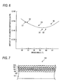
- a hose shown in Fig. 7 is heretofore known as a brake hose used in a vehicle.
- Fig. 7 is a sectional view showing important part of the brake hose 100 according to the related art.
- the brake hose 100 is formed in such a manner that a plurality of rubber and fiber yarn layers are laminated because the brake hose 100 needs to have high pressure resistance to brake oil pressure. That is, the brake hose 100 is formed as a laminate which has: an inner rubber layer 102 for forming a flow path 101 in which brake oil flows; a lower yarn layer 104; an intermediate rubber layer 106; an upper yarn layer 108; and an outer rubber layer 110.
- a technique using high-modulus polyester yarn (high-modulus PET yarn) in the lower yarn layer 104 to keep durability high and using inextensional vinylon yarn in the upper yarn layer 108 to reduce the amount of volumetric expansion is known as a technique for successfully combining durability and expansion resistance with each other (see Japanese Patent No. 2,692,480).
- a technique in which lower yarn constituted by fine fiber yarn is braided to form a thin and dense reinforcing layer to thereby attain improvement in durability and expansion resistance is also known (see Japanese Patent No. 3, 003, 769).
- an object of the invention is to provide a brake hose in which both durability and expansion resistance (the amount of volumetric expansion) can be improved on the basis of examination of the braid angle of reinforcing yarn in each reinforcing layer.
- the brake hose according to the invention is a reinforced hose having an inner rubber layer, an outer rubber layer, and at least two reinforcing layers provided between the inner rubber layer and the jacket layer, including a lower yarn layer formed on the inner rubber layer and an upper yarn layer formed outside of the lower yarn layer, wherein the lower yarn layer is braided from a reinforcing yarn at a braid angle 59 ⁇ 2° with respect to an axial direction of the hose, and the reinforcing yarn is made of polyester yarn having a tensile strength of not lower than 6.9 g per unit dtex and having a stretchability of 2.6 ⁇ 1.0 % at 2.7 g load per unit dtex.
- fluid pressure is transmitted from the inner rubber layer to the reinforcing layers and further transmitted to the outer rubber layer.
- the reinforcing layers operate so that volumetric expansion is suppressed by resistance force which is generated when the reinforcing yarn is stretched in accordance with the change of the fluid pressure.
- the polyester yarn having a tensile strength of not lower than 6.9 g per unit dtex and having a stretchability of 2.6 ⁇ 1.0 % at 2.7 g load per unit dtex can be used as the reinforcing yarn.
- the polyester yarn may comprise a high-modulus PET yarn having a tensile strength of not lower than 6.9 g per unit dtex and having a stretchability of 2.6 ⁇ 1.0 % at 2.7 g load per unit dtex.
- the high-modulus PET yarn is lower in expansion per predetermined load than ordinary PET yarn which has a tensile strength of not lower than 6.6 g per unit dtex and has a stretchability of 4.0 ⁇ 1.0 % at 2.7 g load per unit dtex, the amount of volumetric expansion can be reduced.
- polyester yarn is used in place of vinylon yarn in the lower yarn layer (or the upper yarn layer), the reinforcing layers are also excellent in fatigue resistance.
- unit dtex used herein means the number of grams per 10,000 m of filament yarn.
- the high-modulus PET yarn is higher in the function of suppressing the amount of volumetric expansion than the ordinary PET yarn.
- the braid angle of the reinforcing yarn is set at 59 ⁇ 2°, the amount of volumetric expansion can be suppressed more greatly.
- the reason why the amount of volumetric expansion can be reduced when the braid angle is set to be in the aforementioned range will be described.
- the reinforcing layers are formed in such a manner that the outer circumference of the inner rubber layer is wound with two kinds of reinforcing yarn rotating in clockwise and counterclockwise directions opposite to each other.
- the term "braid angle of reinforcing yarn” means an angle of inclination with respect to the axial direction of the hose.
- the present inventor has found that the amount of volumetric expansion of a reinforced hose having reinforcing layers made of high-modulus PET yarn and embedded between the inner rubber layer and the outer rubber layer can be reduced when the braid angle is set at 59 ⁇ 2°, especially preferably at 59 ⁇ 1° which is larger than the repose angle. That is, the braid angle at which the amount of volumetric expansion can be minimized is equal to the repose angle (54.44°) when examined geometrically, but is equal to 59 ⁇ 2° which is larger than the repose angle when actually applied to the reinforced hose. In consideration of this fact, the braid angle is set to be in the aforementioned range.
- the reinforcing layers are produced as follows. While an inner rubber layer is extrusion-molded from an inner-tube extrudate, reinforcing layers of reinforcing yarn are braided on the inner rubber layer by a braider. Further, an outer rubber layer is extrusion-molded on the reinforcing layers.
- the braid angle of each reinforcing layer can be set on the basis of the ratio of the speed of extruding the inner rubber layer to the rotational speed of the braider.
- the thickness of the inner rubber layer is preferably set at 0.6 ⁇ 0.2 mm, especially preferably set at 0. 6 ⁇ 0.1 mm.
- the outer diameter of the inner rubber layer can be set at a small value. Accordingly, the reinforcing layers can be braided on the inner rubber layer densely and firmly though the amount of reinforcing yarn is small. As a result, the slack or gap between pieces of reinforcing yarn canbe reduced, so that the amount of volumetric expansion can be reduced.
- the inner rubber layer can be hardly extrusion-molded or the pres sure fluid may penetrate into the inner rubber layer if the thickness of the inner rubber layer is smaller than 0.4 mm. It is therefore preferable that the thickness of the inner rubber layer is not smaller than 0.4 mm.
- the reinforcing yarn has a size of 1,100 ⁇ 100 dtex.
- each reinforcing layer with a small outer diameter can be formed so densely that the amount of volumetric expansion can be reduced.
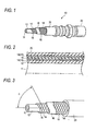
- Fig. 1 is a partly cutaway perspective view showing an embodiment in which a reinforced hose according to the invention is applied to a brake hose 10.
- Fig. 2 is a half-sectional view. of the brake hose 10.
- the brake hose 10 is used so that a master cylinder used in a vehicle oil pressure brake not shown can be connected to a tire side hydraulic device by the brake-hose 10.
- the brake hose 10 is formed as a laminate of five layers so that the brake hose 10 can bear the pressure of brake fluid.
- the brake hose 10 has: an inner rubber layer 12 including a flow path 11; a lower yarn layer 14; an intermediate rubber layer 16; an upper yarn layer 18; and an outer rubber layer 20; wherein a mouse piece 22 is tightened to an end portion of the brake hose by caulking.
- the materials, thicknesses, braid angles, etc. of the respective layers are decided so that the brake hose 10 can have characteristic such as pressure resistance, durability and expansion resistance to withstand maximum brake fluid pressure of 50 MPa.
- the inner rubber layer 12 is extrusion-molded from rubber such as etylene-propylene-diene terpolymer rubber (EPDM), isobutylene-isoprene copolymer rubber (IIR) or styrene-butadiene copolymer rubber (SBR) mainly to obtain oil resistance.
- EPDM etylene-propylene-diene terpolymer rubber
- IIR isobutylene-isoprene copolymer rubber
- SBR styrene-butadiene copolymer rubber
- the inner diameter of the inner rubber layer 12 is selected to be in a range of from 3. 0 mm to 3. 4 mm.
- the thickness of the inner rubber layer 12 is selected to be in a range of from 0.4 mm to 0.8 mm.
- the inner rubber layer When the inner rubber layer is thin, the inner rubber layer is effective in reducing the amount of volumetric expansion. If the inner rubber layer is thinner than 0.4 mm, there is however a possibility that the inner rubber layer will be hardly extrusion-molded or will be made permeable to pressure fluid. It is therefore preferable that the thickness of the inner rubber layer is not smaller than 0.4 mm.
- the lower yarn layer 14 is formed on the inner rubber layer 12 so as to be braided from 20 or 24 carriers of lower yarn 15 each made of two- or three-strand high-modulus PET yarn.
- Polyester yarn having a tensile strength of not lower than 6.9 g per unit dtex and having a stretchability of 2.6 ⁇ 1.0 % at 2.7 g load per unit dtex is used as the high-modulus PET yarn. More preferably, polyester yarn having a tensile strength of not lower than 6.9 g per unit dtex and having a stretchability of 2.6 ⁇ 0.5 % at 2.7 g load per unit dtex is used as the high-modulus PET yarn.
- the lower yarn 15 is formed as a bundle of 200 to 400 pieces of filament yarn.
- the term "RFL process” used herein means a process in which an adhesive thin film serving as an adhesive agent and containing resorcin-formaldehyde-latex resin and rubber latex as main components is applied on a surface of yarn.
- the thickness of the lower yarn layer 14 is selected to be in a range of from 0. 55 mm to 0. 95 mm, preferably in a range of from 0.65 mm to 0.85 mm.
- the braid angle of the lower yarn layer 14 is set at 59 + 2°, preferably 59 ⁇ 1° to reduce the amount of volumetric expansion.
- Fig. 3 is an explanatory view for explaining the braid angle of the lower yarn layer 14. As shown in Fig. 3, the lower yarn layer 14 is formed on the inner rubber layer 12 so as to be helically braided from the lower yarn 15 at a braid angle ⁇ .
- the term "braid angle ⁇ " used herein means an angle of the lower yarn 15 with respect to the axial direction of the hose.
- the braid angle ⁇ can be changed on the basis of the ratio of the speed of extruding the inner rubber layer to the rotational speed of the braider.
- the intermediate rubber layer 16 is a layer for preventing the lower yarn layer 14 and the upper yarn layer 18 from being displaced.
- the intermediate rubber layer 16 is formed by a method such as a method of extruding a rubber material onto the lower yarn layer 14, a method of winding a sheet material 16A on the lower yarn layer 14 or a method of applying rubber paste on the lower yarn layer 14.
- EPDM, isobutylene-isoprene copolymer rubber (IIR) or natural rubber (NR) can be used as the rubber material.
- IIR isobutylene-isoprene copolymer rubber
- NR natural rubber
- the thickness of the intermediate rubber layer 16 is preferably selected to be in a range of from 0.1 mm to 0.35 mm. The reason is as follows. If the intermediate rubber layer 16 is thinner than 0.1 mm, the intermediate rubber layer 16 is too thin to be formed on the lower yarn layer 14. On the other hand, if the intermediate rubber layer 16 is thicker than 0.35 mm, the function of suppressing the displacement of the lower yarn layer 14 is reduced because the thick intermediate rubber layer 16 serves as an elastic layer allowing the displacement of the lower yarn layer 14.
- the upper yarn layer 18 is formed in the same manner as the lower yarn layer 15. That is, 200 to 400 pieces of filament yarn are bundled to form high-modulus PET yarn. After an REL process, two or three pieces of high-modulus PET yarn are plied into upper yarn 19. 20 or 24 carriers of the upper yarn 19 are braided on the intermediate rubber layer 16. In this manner, the upper yarn layer 18 is formed.
- the braid angle of the upper yarn layer 18 is preferably set at 59 ⁇ 2°, especially preferably at 59 ⁇ 1° which is larger than the repose angle, to reduce the amount of volumetric expansion.
- the outer rubber layer 20 is made of a material such as EPDM or a blend of EPDM and CR mainly to obtain ozone resistance.
- the thickness of the outer rubber layer 20 is selected to be in a range of from 0.8 mm to 1.3 mm.
- the brake hose 10 can be produced by a commonly known method, that is, by a rubber extruding step, a fiber yarn braiding step and a vulcanizing step.
- Fig. 4 is an explanatory view for explaining a hose producing apparatus 30.
- the hose producing apparatus 30 has a first extruder 31, a first braider 32, an intermediate sheet former 34, a second braider 35, and a second extruder 37.
- the first extruder 31 is a device for extruding the rubber material to form the inner rubber layer 12.
- the first braider 32 is a device which has a bobbin carrier mounted in a drum 32a and which is provided for braiding the lower yarn 15 on the inner-tube extrudate 12A while feeding the lower yarn 15 out of the bobbin carrier to thereby form the lower yarn layer 14.
- the intermediate sheet former 34 is a device for feeding the sheet material 16A out of a roller to thereby form the intermediate rubber layer 16 on the lower yarn layer 14 braided by the first braider 32.
- the second braider 35 substantially has the same configuration as that of the first braider 32. That is, the second braider 35 is a device which has a bobbin carrier mounted in a drum 35a and which is provided for braiding the upper yarn 19 on the intermediate rubber layer 16 while feeding the upper yarn 19 out of the bobbin carrier to thereby form the upper yarn layer 18.
- the second extruder 37 is a device for extruding the rubber material to form the outer rubber layer 20.
- a series of steps for producing the brake hose 10 by the hose producing apparatus 30 will be described below with reference to Fig. 3.
- the rubber material is extruded by the first extruder 31 to thereby form the inner rubber layer 12.
- a mandrel (not shown) is inserted in the inner rubber layer 12.
- pieces of lower yarn 15 are fed out of bobbins onto the extruded inner rubber layer 12 while the drum 32a of the first braider 32 rotates, so that the lower yarn layer 14 is braided from the pieces of lower yarn 15 on the inner rubber layer 12.
- the 20 carriers of lower yarn 15 are fed out of twenty bobbins in twenty locations in total while the twenty bobbins rotate in reverse directions alternately.
- the braid angle ⁇ of the lower yarn layer 14 can be set at 59 ⁇ 2° on the basis of the ratio of the speed of extruding the inner rubber layer 12 to the rotational speed of the drum 32a.
- the intermediate sheet former 34 supplies the sheet material 16A onto the lower yarn layer 14 to thereby form the intermediate rubber layer 16.
- the vulcanizing step is carried out.
- Atemperature of 120°C to 170°C and a time of 15 minutes to 60 minutes are set as a condition for the vulcanizing step.
- the upper yarn layer 18 and the lower yarn layer 14 subj ected to the RFL process by heat generated in the vulcanizing step are bonded to the inner rubber layer 12, the intermediate rubber layer 16 and the outer rubber layer 20. In this manner, the brake hose 10 is formed integrally.
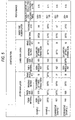
- Fig. 5 shows the configuration andperformance of a brake hose sample produced in each of Examples 1 and 2 and Comparative Examples 1 and 2.
- Each brake hose sample was produced to have an inner diameter of 3.1 mm to 3.2 mm and an outer diameter of 10.2 mm to 10.5 mm.
- the braid angle ⁇ of the lower yarn layer was set at 59° while high-modulus PET yarn was used both in the upper yarn layer and in the lower yarn layer.
- the high-modulus PET yarn used in Example 1 has a size of 1670 dtex and has a tensile strength of not lower than 11.5 Kg for 1670 dtex and a stretchability of 2.6 ⁇ 1.0 % at 4.5 Kg load for 1670 dtex.
- the high-modulus PET yarn used in Example 2 has a size of 1100 dtex smaller than the size of fiber yarn in Example 1 and has a tensile strength of not lower than 7.6 Kg for 1100 dtex and a stretchability of 2.6 ⁇ 1.0 % at 3.0 Kg load for 1100 dtex.
- the braid angle ⁇ of the lower yarn layer was not larger than 56°.
- PET yarn was used both in the upper yarn layer and in the lower yarn layer.
- high-modulus PET yarn was used in the lower yarn layer while polyvinyl alcohol (PVA) yarn was used in the upper yarn layer. That is, Comparative Example 2 shows an example described in Japanese Patent No. 2692480.
- the durability test was carried out as a repeated pressure test in which brake pressure oil was actually applied to the brake hose. That is, repeated pressurizing due to brake fluid pressure was combinedwithbumpingandsteeringmotionto imitate motion of tires in the condition that the brake hose was disposed in the same course as actually disposed in a vehicle.
- the brake fluid pressure was applied so that a pressure of 0 MPa and a pressure of 9.8 MPa were repeated alternately at 0.7 Hz.
- the bumping motion was repeated at 2.5 Hz.
- the bumping motion was repeated at 0.28 Hz. In this condition, the number of times of steering motion up to the breaking of the brake hose was examined. As a result, it was found that durability was not changed even in Examples in which high-modulus PET yarn was used both in the upper yarn layer and in the lower yarn layer while thebraidanglewas set to be larger than that in Comparative Examples.
- the volumetric expansion test was carried out in such a manner that the amount of change in internal volume of the brake hose having a free length of 305 mm (1 foot) was measured under an oil pressure of 10.3 MPa in accordance with JIS-2601. It was found that the amount of volumetric expansion in each of Examples 1 and 2 was reduced compared with that in each of Comparative Examples 1 and 2.
- Fig. 6 is a graph showing the relation between the braid angle and the amount of volumetric expansion.
- the brake hose was produced to have an outer diameter of 10.2 mm while the braid angle ⁇ of the upper yarn layer 18 was set at 59°.
- the braid angle ⁇ was changed variously to prepare samples S1 to S6.
- the amount of volumetric expansion of each sample was measured. As a result, it was found that the amount of volumetric expansion decreased when the braid angle ⁇ exceeded 57° as represented by the samples S3 to S6. It was also found that the amount of volumetric expansion increased when the braid angle ⁇ exceeded 61°.
- the invention is not limited to the aforementioned embodiment and various modifications may be made without departing from the gist of the invention.
- the invention may be modified as follows.
- the invention is not limited thereto but may be applied to a power steering hose of a vehicle or a hydraulic hose for building equipment as long as the hose is a high-pressure hose.
Landscapes
- Engineering & Computer Science (AREA)
- General Engineering & Computer Science (AREA)
- Mechanical Engineering (AREA)
- Rigid Pipes And Flexible Pipes (AREA)
- Laminated Bodies (AREA)
Applications Claiming Priority (2)
| Application Number | Priority Date | Filing Date | Title |
|---|---|---|---|
| JP2003352509A JP2005114135A (ja) | 2003-10-10 | 2003-10-10 | 補強ホース |
| JP2003352509 | 2003-10-10 |
Publications (2)
| Publication Number | Publication Date |
|---|---|
| EP1522781A1 true EP1522781A1 (de) | 2005-04-13 |
| EP1522781B1 EP1522781B1 (de) | 2006-04-19 |
Family
ID=34309293
Family Applications (1)
| Application Number | Title | Priority Date | Filing Date |
|---|---|---|---|
| EP04024048A Expired - Lifetime EP1522781B1 (de) | 2003-10-10 | 2004-10-08 | Armierter Schlauch |
Country Status (5)
| Country | Link |
|---|---|
| US (1) | US7017616B2 (de) |
| EP (1) | EP1522781B1 (de) |
| JP (1) | JP2005114135A (de) |
| CN (1) | CN1295457C (de) |
| DE (1) | DE602004000682T2 (de) |
Families Citing this family (22)
| Publication number | Priority date | Publication date | Assignee | Title |
|---|---|---|---|---|
| JP2006105313A (ja) * | 2004-10-07 | 2006-04-20 | Yokohama Rubber Co Ltd:The | 高圧ゴムホース |
| JP2006266442A (ja) * | 2005-03-25 | 2006-10-05 | Toyoda Gosei Co Ltd | ブレーキホース |
| US7328725B2 (en) * | 2005-08-15 | 2008-02-12 | Eaton Corporation | Reinforced hose |
| US7900978B2 (en) * | 2006-02-02 | 2011-03-08 | Sargent Manufacturing Company | Return spring assembly for a lock mechanism |
| US20070181202A1 (en) * | 2006-02-03 | 2007-08-09 | Electrovations, Inc., A Corporation Of The State Of Ohio | Brake hose |
| DE102007005195A1 (de) * | 2007-01-29 | 2008-07-31 | Tecno Plast Industrietechnik Gmbh | Silikonschlauch und Schlauchanschluss |
| CN101158426A (zh) * | 2007-10-12 | 2008-04-09 | 上海登益企业有限公司 | 一种液压传输用高压管 |
| US8783300B2 (en) * | 2009-08-14 | 2014-07-22 | Kongsberg Actuation Systems Ii, Inc. | Hose assembly and method of forming the same |
| CN101780720B (zh) * | 2010-03-15 | 2012-12-12 | 义乌市金佐消防水带厂 | 三元乙丙消防水带的生产方法 |
| US8752591B2 (en) * | 2010-06-10 | 2014-06-17 | Veyance Technologies, Inc | Kink, crush, and burst resistant flexible hose |
| US9073278B2 (en) | 2011-10-27 | 2015-07-07 | The Goodyear Tire & Rubber Company | Geodesic pneumatic tire with braided carcass |
| JP2013202965A (ja) * | 2012-03-29 | 2013-10-07 | Toyoda Gosei Co Ltd | 補強ホースの製造方法 |
| US9115831B2 (en) * | 2013-06-24 | 2015-08-25 | E I Du Pont De Nemours And Company | Multilayer reinforced hose |
| EP3051195A4 (de) * | 2013-09-27 | 2017-07-19 | Kolon Industries, Inc. | Bremsschlauch |
| CN104175582A (zh) * | 2014-07-28 | 2014-12-03 | 保定建强制动软管有限公司 | 一种机动车制动软管的生产方法和装置 |
| JP6553903B2 (ja) * | 2015-03-19 | 2019-07-31 | 住友理工株式会社 | 樹脂成形品の製造方法 |
| CN105257921B (zh) * | 2015-11-03 | 2017-08-04 | 青岛三祥科技股份有限公司 | 低膨胀、高粘合、耐制动液的离合器软管 |
| JP6706775B2 (ja) * | 2015-12-22 | 2020-06-10 | 株式会社ニチリン | ブレーキホース |
| BR112019007391B1 (pt) * | 2016-10-13 | 2022-08-23 | Parker-Hannifin Corporation | Montagem de mangueira e sistema de mangueira |
| US10066766B1 (en) | 2017-05-23 | 2018-09-04 | Contitech Usa, Inc. | Hose inner layer formed of ECO blended with NBR/PVC |
| US10907763B2 (en) | 2019-03-22 | 2021-02-02 | North American Fire Hose Corporation | Heat resistant hose |
| CN112976625A (zh) * | 2021-02-03 | 2021-06-18 | 青岛威尔驰液压科技有限公司 | 一种多用胶管编织机及生产胶管的方法 |
Citations (4)
| Publication number | Priority date | Publication date | Assignee | Title |
|---|---|---|---|---|
| US4668319A (en) * | 1983-12-19 | 1987-05-26 | The Goodyear Tire & Rubber Company | Method of manufacture of a braided hose |
| US4668318A (en) * | 1983-12-19 | 1987-05-26 | The Goodyear Tire & Rubber Company | Method for producing braided spiral reinforced hose |
| EP1314925A1 (de) * | 2001-11-27 | 2003-05-28 | Toyoda Gosei Co., Ltd. | Bremsschlauch |
| EP1314924A1 (de) * | 2001-11-27 | 2003-05-28 | Toyoda Gosei Co., Ltd. | Bremsschlauch und dessen Herstellungsverfahren |
Family Cites Families (13)
| Publication number | Priority date | Publication date | Assignee | Title |
|---|---|---|---|---|
| GB1253178A (de) * | 1970-07-16 | 1971-11-10 | ||
| US4111237A (en) * | 1976-07-12 | 1978-09-05 | General Motors Corporation | Braid reinforced flexible brake hose |
| FR2597568B1 (fr) * | 1986-04-18 | 1988-07-08 | Tecalemit Flexibles | Nouveau tuyau flexible destine a etre utilise a haute pression et son procede de fabrication |
| CN2071738U (zh) * | 1990-08-15 | 1991-02-20 | 沈阳胶管厂 | 微机输油软管 |
| JP2692480B2 (ja) | 1992-03-05 | 1997-12-17 | 豊田合成株式会社 | 補強ホース |
| EP0559169B1 (de) * | 1992-03-05 | 1997-07-23 | Toyoda Gosei Co., Ltd. | Verstärkter Schlauch |
| FR2712370B1 (fr) * | 1993-11-09 | 1996-01-19 | Nobel Plastiques | Canalisation pour fluide de réfrigération. |
| US5445191A (en) * | 1994-08-11 | 1995-08-29 | General Motors Corporation | High pressure brake hose with reinforcing layer of nonwater-based adhesive coated polyvinyl alcohol fibers |
| JP3003769B2 (ja) * | 1995-08-28 | 2000-01-31 | 日立電線株式会社 | 液圧ホース |
| JP3806974B2 (ja) * | 1996-06-14 | 2006-08-09 | 豊田合成株式会社 | 冷媒輸送用ホース |
| SE9703109D0 (sv) * | 1997-08-29 | 1997-08-29 | Trelleborg Viking As | Korrosionsbeständigt rörmaterial samt don för anslutning till rör av sådant material |
| DE1253364T1 (de) * | 2000-02-04 | 2003-08-14 | Kabushiki Kaisha Meiji Gomu Kasei, Tokio/Tokyo | Gummibremsschlauch mit sehr niedriger ausdehnung und dazugehöriges herstellungsverfahren |
| CN2462181Y (zh) * | 2001-02-13 | 2001-11-28 | 王茂峰 | 纤维编织增强的塑料高压软管 |
-
2003
- 2003-10-10 JP JP2003352509A patent/JP2005114135A/ja not_active Withdrawn
-
2004
- 2004-10-07 US US10/959,405 patent/US7017616B2/en not_active Expired - Lifetime
- 2004-10-08 EP EP04024048A patent/EP1522781B1/de not_active Expired - Lifetime
- 2004-10-08 DE DE602004000682T patent/DE602004000682T2/de not_active Expired - Lifetime
- 2004-10-09 CN CNB200410084997XA patent/CN1295457C/zh not_active Expired - Fee Related
Patent Citations (4)
| Publication number | Priority date | Publication date | Assignee | Title |
|---|---|---|---|---|
| US4668319A (en) * | 1983-12-19 | 1987-05-26 | The Goodyear Tire & Rubber Company | Method of manufacture of a braided hose |
| US4668318A (en) * | 1983-12-19 | 1987-05-26 | The Goodyear Tire & Rubber Company | Method for producing braided spiral reinforced hose |
| EP1314925A1 (de) * | 2001-11-27 | 2003-05-28 | Toyoda Gosei Co., Ltd. | Bremsschlauch |
| EP1314924A1 (de) * | 2001-11-27 | 2003-05-28 | Toyoda Gosei Co., Ltd. | Bremsschlauch und dessen Herstellungsverfahren |
Also Published As
| Publication number | Publication date |
|---|---|
| EP1522781B1 (de) | 2006-04-19 |
| DE602004000682T2 (de) | 2007-05-10 |
| JP2005114135A (ja) | 2005-04-28 |
| CN1605786A (zh) | 2005-04-13 |
| CN1295457C (zh) | 2007-01-17 |
| US7017616B2 (en) | 2006-03-28 |
| US20050121095A1 (en) | 2005-06-09 |
| DE602004000682D1 (de) | 2006-05-24 |
Similar Documents
| Publication | Publication Date | Title |
|---|---|---|
| EP1522781B1 (de) | Armierter Schlauch | |
| CA2716382C (en) | Controlled expansion hose | |
| US6807988B2 (en) | Thermoplastic reinforced hose construction | |
| CA2152766C (en) | High pressure brake hose with extended impulse life | |
| AU2002243482A1 (en) | Thermoplastic reinforced hose construction and method of making the same | |
| CN110461586A (zh) | 高压紧凑的螺旋液压软管 | |
| US6626211B2 (en) | Brake hose | |
| WO2007020503A2 (en) | Reinforced hose | |
| EP1314924B1 (de) | Bremsschlauch und dessen Herstellungsverfahren | |
| WO2007120366A2 (en) | Brake hose | |
| US20050136203A1 (en) | Hose assembly having varied reinforcing layers | |
| US7140395B2 (en) | Brake hose | |
| JP2010096354A (ja) | ブレーキホース | |
| JP2003161388A (ja) | ブレーキホース |
Legal Events
| Date | Code | Title | Description |
|---|---|---|---|
| PUAI | Public reference made under article 153(3) epc to a published international application that has entered the european phase |
Free format text: ORIGINAL CODE: 0009012 |
|
| 17P | Request for examination filed |
Effective date: 20041008 |
|
| AK | Designated contracting states |
Kind code of ref document: A1 Designated state(s): AT BE BG CH CY CZ DE DK EE ES FI FR GB GR HU IE IT LI LU MC NL PL PT RO SE SI SK TR |
|
| AX | Request for extension of the european patent |
Extension state: AL HR LT LV MK |
|
| GRAP | Despatch of communication of intention to grant a patent |
Free format text: ORIGINAL CODE: EPIDOSNIGR1 |
|
| AKX | Designation fees paid |
Designated state(s): DE FR GB |
|
| GRAS | Grant fee paid |
Free format text: ORIGINAL CODE: EPIDOSNIGR3 |
|
| GRAA | (expected) grant |
Free format text: ORIGINAL CODE: 0009210 |
|
| AK | Designated contracting states |
Kind code of ref document: B1 Designated state(s): DE FR GB |
|
| REG | Reference to a national code |
Ref country code: GB Ref legal event code: FG4D |
|
| REF | Corresponds to: |
Ref document number: 602004000682 Country of ref document: DE Date of ref document: 20060524 Kind code of ref document: P |
|
| ET | Fr: translation filed | ||
| PLBE | No opposition filed within time limit |
Free format text: ORIGINAL CODE: 0009261 |
|
| STAA | Information on the status of an ep patent application or granted ep patent |
Free format text: STATUS: NO OPPOSITION FILED WITHIN TIME LIMIT |
|
| 26N | No opposition filed |
Effective date: 20070122 |
|
| PGFP | Annual fee paid to national office [announced via postgrant information from national office to epo] |
Ref country code: FR Payment date: 20091029 Year of fee payment: 6 Ref country code: GB Payment date: 20091007 Year of fee payment: 6 |
|
| GBPC | Gb: european patent ceased through non-payment of renewal fee |
Effective date: 20101008 |
|
| PG25 | Lapsed in a contracting state [announced via postgrant information from national office to epo] |
Ref country code: FR Free format text: LAPSE BECAUSE OF NON-PAYMENT OF DUE FEES Effective date: 20101102 |
|
| REG | Reference to a national code |
Ref country code: FR Ref legal event code: ST Effective date: 20110630 |
|
| PG25 | Lapsed in a contracting state [announced via postgrant information from national office to epo] |
Ref country code: GB Free format text: LAPSE BECAUSE OF NON-PAYMENT OF DUE FEES Effective date: 20101008 |
|
| PGFP | Annual fee paid to national office [announced via postgrant information from national office to epo] |
Ref country code: DE Payment date: 20200922 Year of fee payment: 17 |
|
| REG | Reference to a national code |
Ref country code: DE Ref legal event code: R119 Ref document number: 602004000682 Country of ref document: DE |
|
| PG25 | Lapsed in a contracting state [announced via postgrant information from national office to epo] |
Ref country code: DE Free format text: LAPSE BECAUSE OF NON-PAYMENT OF DUE FEES Effective date: 20220503 |