EP1522779B1 - Kryogenes Ventil mit einem Hebelantrieb - Google Patents
Kryogenes Ventil mit einem Hebelantrieb Download PDFInfo
- Publication number
- EP1522779B1 EP1522779B1 EP04023707A EP04023707A EP1522779B1 EP 1522779 B1 EP1522779 B1 EP 1522779B1 EP 04023707 A EP04023707 A EP 04023707A EP 04023707 A EP04023707 A EP 04023707A EP 1522779 B1 EP1522779 B1 EP 1522779B1
- Authority
- EP
- European Patent Office
- Prior art keywords
- valve
- cryogenic
- lever
- pneumatic cylinder
- spring
- Prior art date
- Legal status (The legal status is an assumption and is not a legal conclusion. Google has not performed a legal analysis and makes no representation as to the accuracy of the status listed.)
- Expired - Lifetime
Links
- 238000004519 manufacturing process Methods 0.000 description 1
- 238000000926 separation method Methods 0.000 description 1
- 230000008646 thermal stress Effects 0.000 description 1
Images


Classifications
-
- F—MECHANICAL ENGINEERING; LIGHTING; HEATING; WEAPONS; BLASTING
- F16—ENGINEERING ELEMENTS AND UNITS; GENERAL MEASURES FOR PRODUCING AND MAINTAINING EFFECTIVE FUNCTIONING OF MACHINES OR INSTALLATIONS; THERMAL INSULATION IN GENERAL
- F16K—VALVES; TAPS; COCKS; ACTUATING-FLOATS; DEVICES FOR VENTING OR AERATING
- F16K31/00—Actuating devices; Operating means; Releasing devices
- F16K31/12—Actuating devices; Operating means; Releasing devices actuated by fluid
- F16K31/16—Actuating devices; Operating means; Releasing devices actuated by fluid with a mechanism, other than pulling-or pushing-rod, between fluid motor and closure member
- F16K31/163—Actuating devices; Operating means; Releasing devices actuated by fluid with a mechanism, other than pulling-or pushing-rod, between fluid motor and closure member the fluid acting on a piston
Definitions
- the invention relates to a cryogenic valve for delivering a cryogenic medium with an actuator and a pneumatic cylinder.
- a valve of this type is from the document US 3260496 already known.
- Actuators of this type are from the publications US 5074325 . US 2,490,555 and FR 852211 already known.
- the invention is therefore an object of the invention to provide an actuator for a cryogenic valve available, which is easy to manufacture and reliable to operate.
- the stated object is achieved in that the pneumatic cylinder is connected via a lever with the valve needle in operative connection, wherein the lever is rotatably connected on one side with a linkage.
- the invention enables a spatial separation of the pneumatic from the valve, so that no transfer of cold from the cryogenic valve can take place on the pneumatic parts. This will ensure that the pneumatic parts are at about room temperature. Avoiding the exposure of the pneumatics to very cold temperatures prevents wear effects due to thermal stresses in the components and ensures reliable operation of the pneumatics and thus of the valve actuation.
- This embodiment of the actuator according to the invention requires a double-acting pneumatic cylinder, which opens the valve when extending in one direction and when closing in the other direction (retraction) closes the valve.
- the linkage itself is rotatably mounted. This has the advantage that during the extension and retraction of the pneumatic cylinder, a small relative movement of the linkage is possible per se, thereby preventing a tilting action on the valve. While a rigid attachment of the linkage in small Valve movements or small angular movements of the lever is still tolerable, the rotation allows greater movements.
- the lever may be connected to a spring.
- the spring may preferably be attached to the other side of the lever - ie opposite the linkage.
- valve, the pneumatic cylinder and the linkage - and possibly the spring - are arranged side by side and jointly access the lever.
- the juxtaposition of the elements leads to a short height, which is advantageous especially when used in cryogenic environments.
- the pneumatic cylinder - and possibly the spring - on one side of the valve, while the linkage is arranged on the other side of the valve results in the opening and closing movements to a reduction, since the valve is now arranged between the pneumatic cylinder and the linkage 6, so that an extension movement of the pneumatic cylinder leads to a smaller opening movement in the valve.
- This reduction allows an extremely fine movement of the valve head in the valve seat and leads to a very precise dosage.
- the figures show an actuator for a cryogenic valve 1 with a pneumatic cylinder 2.
- the pneumatic cylinder 2 is connected via a lever 3 with the valve needle 4, wherein the lever 3 is connected on one side with a spring 5 and rotatable on the other side is connected to a rotatably mounted linkage 6.
- the spring 5 By extending the piston of the pneumatic cylinder 2, the spring 5 is stretched, the valve needle 4 is withdrawn and the valve 1 is brought into the open valve position.
- the cryogenic medium can be dispensed from the valve in this position.
- valve 1 To close the valve 1, the restoring force of the spring 5 is used, the valve needle 4 moves toward the valve seat and closes the valve 1. The delivery of cryogenic medium is thus prevented, the valve 1 is closed.
- the embodiment without spring is not shown here. It differs from the embodiment shown in that the spring 5 is omitted and the pneumatic cylinder 2 is a double-acting cylinder. Of course, the lever 3 can then be made shorter. Opening and closing is done by moving the piston of the pneumatic cylinder 2 up or down.
Landscapes
- Engineering & Computer Science (AREA)
- General Engineering & Computer Science (AREA)
- Mechanical Engineering (AREA)
- Mechanically-Actuated Valves (AREA)
- Fluid-Driven Valves (AREA)
- Temperature-Responsive Valves (AREA)
- Details Of Valves (AREA)
- Magnetically Actuated Valves (AREA)
- Actuator (AREA)
- Valve Device For Special Equipments (AREA)
- Lift Valve (AREA)
Description
- Die Erfindung betrifft einen kryogenes Ventil zur Abgabe eines Kryogenen Mediums mit einen Betätiger und einem pneumatischen Zylinder.
- Ein Ventil dieser Art ist aus der Druckschrift
US 3260496 bereits bekannt. - Bekannt sind verschiedene mechanische, elektrische oder pneumatische Betätiger für ein Ventil. Die bekannten Lösungen sind allerdings wenig zur Betätigung eines kryogenen Ventils geeignet, d. h. zur Betätigung eines Ventils, das ein kryogenes Medium, wie z. B. tiefkaltes verflüssigtes Gas, abgibt.
- Betätiger dieser Art sind aus den Druckschriften
US 5074325 ,US 2490555 undFR 852211 - Der Erfindung liegt daher die Aufgabe zugrunde, einen Betätiger für ein kryogenes Ventil zur Verfügung zu stellen, der einfach herzustellen und zuverlässig zu betreiben ist.
- Die gestellte Aufgabe wird dadurch gelöst, dass der pneumatische Zylinder über einen Hebel mit der Ventilnadel in Wirkverbindung steht, wobei der Hebel an einer Seite drehbar mit einem Gestänge verbunden ist.
- Die Erfindung ermöglicht eine räumliche Trennung der Pneumatik von dem Ventil, so dass kein Kälteübertrag von dem kryogenen Ventil auf die pneumatischen Teile stattfinden kann. Dadurch wird sichergestellt, dass die pneumatischen Teile in etwa der Raumtemperatur ausgesetzt sind. Die Vermeidung der Exposition der Pneumatik an sehr kalte Temperaturen verhindert Verschleißeffekte durch thermische Spannungen in den Bauteilen und stellt einen zuverlässigen Betrieb der Pneumatik und somit der Ventilbetätigung sicher. Diese Ausführung des erfindungsgemäßen Betätigers benötigt einen doppelt wirkenden pneumatischen Zylinder, der beim Ausfahren in die eine Richtung das Ventil öffnet und beim Ausfahren in die andere Richtung (Einfahren) das Ventil schließt.
- In einer Ausführungsform ist das Gestänge selbst drehbar gelagert. Dies hat den Vorteil, dass beim Ein- und Ausfahren des Pneumatikzylinders eine kleine Relativbewegung des Gestänges an sich möglich ist und dadurch eine Kippwirkung auf das Ventil verhindert wird. Während eine starre Befestigung des Gestänges bei kleinen Ventilbewegungen oder kleinen Winkelbewegungen des Hebels noch tolerierbar ist, erlaubt die Drehbarkeit größere Bewegungen.
- In einer bevorzugten Ausführung der Erfindung kann der Hebel mit einer Feder verbunden sein. Die Feder kann bevorzugt an der anderen Seite des Hebels - also gegenüber dem Gestänge - befestigt sein. Mit Verwendung einer Feder kann als pneumatischer Zylinder ein einfach wirkender pneumatischer Zylinder eingesetzt werden, der dann nur für das Öffnen des Ventils sorgt. Zum Schließen des Ventils wird er druckfrei geschaltet und die Feder zieht durch Ihre Spannkraft das Ventil wieder in die Schließstellung. Dies hat die Vorteile, dass ein preisgünstigeres pneumatisches Bauteil verwendet werden kann und dass der Anliegedruck der Ventilnadel im Ventilsitz durch die Feder exakt vorbestimmt werden kann.
- In einer bevorzugten Ausführung der Erfindung sind das Ventil, der pneumatische Zylinder und das Gestänge - und ggf. die Feder - nebeneinander stehend angeordnet und greifen gemeinsam auf den Hebel zu. Die nebeneinander stehende Anordnung der Elemente führt zu einer kurzen Bauhöhe, die gerade beim Einsatz in kryogenen Umgebungen vorteilhaft ist.
- In einer bevorzugten Ausführung der Erfindung stehen der pneumatische Zylinder - und ggf. die Feder- auf einer Seite des Ventils, während das Gestänge auf der anderen Seite des Ventils angeordnet ist. Dies führt beim Öffnen und Schließbewegungen zu einer Untersetzung, da das Ventil nun zwischen dem pneumatischen Zylinder und dem Gestänge 6 angeordnet ist, so dass eine Ausfahrbewegung des pneumatischen Zylinders zu einer kleineren Öffnungsbewegung im Ventil führt. Diese Untersetzung erlaubt eine äußerst feine Bewegung des Ventilkopfes im Ventilsitz und führt zu einer sehr exakten Dosierung.
- Die Erfindung sowie weitere Einzelheiten der Erfindung werden im Folgenden anhand eines in den Figuren schematisch dargestellten Ausführungsbeispiels näher erläutert. Hierbei zeigen die
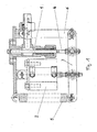
- Figur 1
- einen erfindungsgemäßen Betätiger mit einem kryogenen Ventil in geschlossener Ventilstellung
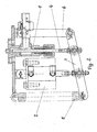
- Figur 2
- einen erfindungsgemäßen Betätiger mit einem kryogenen Ventil in offener Ventilstellung
- Figur 3
- eine isometrische Darstellung des erfindungsgemäßen Betätigers mit kryogenem Ventil
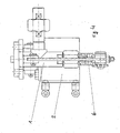
- Figur 4
- eine Seitenansicht des erfindungsgemäßen Betätigers mit kryogenem Ventil
- Figur 5
- eine weitere Seitenansicht des erfindungsgemäßen Betätigers mit kryogenem Ventil
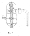
- Figur 6
- eine Draufsicht des erfindungsgemäßen Betätigers mit kryogenem Ventil
- Die Figuren zeigen einen Betätiger für ein kryogenes Ventil 1 mit einem pneumatischen Zylinder 2. Der pneumatische Zylinder 2 ist über einen Hebel 3 mit der Ventilnadel 4 verbunden, wobei der Hebel 3 an einer Seite mit einer Feder 5 verbunden ist und an der anderen Seite drehbar mit einem drehbar gelagerten Gestänge 6 verbunden ist.
- Durch Ausfahren des Kolbens des pneumatischen Zylinders 2 wird die Feder 5 gedehnt, die Ventilnadel 4 wird zurückgezogen und das Ventil 1 wird in die offene Ventilstellung gebracht. Das kryogenen Medium kann in dieser Stellung vom Ventil abgegeben werden.
- Zur Schließung des Ventils 1 wird die Rückstellkraft der Feder 5 benutzt, die Ventilnadel 4 bewegt sich in Richtung Ventilsitz und schließt das Ventil 1. Die Abgabe von kryogenem Medium ist damit unterbunden, das Ventil 1 ist geschlossen.
- Die Ausführungsform ohne Feder ist hier nicht gezeigt. Sie unterscheidet sich von der gezeigten Ausführung dadurch, dass die Feder 5 weggelassen ist und der pneumatische Zylinder 2 ein doppelt wirkender Zylinder ist. Der Hebel 3 kann dann selbstverständlich kürzer ausgebildet sein. Öffnen und Schließen erfolgt durch Verfahren des Kolbens des pneumatischen Zylinders 2 nach oben oder nach unten.
Claims (5)
- Kryogenes Ventil (1) zur Abgabe eines kryogenen Mediums mit einem Betätiger und einem pneumatischen Zylinder (2), dadurch gekennzeichnet, dass der pneumatische Zylinder (2) über einen Hebel (3) mit der Ventilnadel (4) in Wirkverbindung steht, wobei der Hebel (3) an einer Seite drehbar mit einem Gestänge (6) verbunden ist.
- Kryogenes Ventil nach Anspruch 1, dadurch gekennzeichnet, dass das Gestänge (6) drehbar gelagert ist.
- Kryogenes Ventil nach Anspruch 1 oder 2, dadurch gekennzeichnet, dass der Hebel (3) - bevorzugt an seiner anderen Seite - mit einer Feder (5) verbunden ist.
- Kryogenes Ventil nach einem der vorhergehenden Ansprüche, dadurch gekennzeichnet, dass das Ventil (1), der pneumatische Zylinder (2), das Gestänge (6) und gegebenenfalls die Feder (5) nebeneinander stehend angeordnet sind.
- Kryogenes Ventil nach einem der vorhergehenden Ansprüche, dadurch gekennzeichnet, dass der pneumatische Zylinder - und ggf. die Feder (5) - auf einer Seite des Ventils (1) und das Gestänge (6) auf der anderen Seite des Ventils (1) angeordnet sind.
Priority Applications (1)
| Application Number | Priority Date | Filing Date | Title |
|---|---|---|---|
| PL04023707T PL1522779T3 (pl) | 2003-10-10 | 2004-10-05 | Zawór kriogeniczny z napędem dźwigniowym |
Applications Claiming Priority (2)
| Application Number | Priority Date | Filing Date | Title |
|---|---|---|---|
| DE10347127A DE10347127A1 (de) | 2003-10-10 | 2003-10-10 | Hebelantrieb für ein kryogenes Ventil |
| DE10347127 | 2003-10-10 |
Publications (2)
| Publication Number | Publication Date |
|---|---|
| EP1522779A1 EP1522779A1 (de) | 2005-04-13 |
| EP1522779B1 true EP1522779B1 (de) | 2007-08-29 |
Family
ID=34306353
Family Applications (1)
| Application Number | Title | Priority Date | Filing Date |
|---|---|---|---|
| EP04023707A Expired - Lifetime EP1522779B1 (de) | 2003-10-10 | 2004-10-05 | Kryogenes Ventil mit einem Hebelantrieb |
Country Status (9)
| Country | Link |
|---|---|
| US (1) | US7156364B2 (de) |
| EP (1) | EP1522779B1 (de) |
| AT (1) | ATE371829T1 (de) |
| BR (1) | BRPI0404428B1 (de) |
| DE (2) | DE10347127A1 (de) |
| DK (1) | DK1522779T3 (de) |
| ES (1) | ES2291794T3 (de) |
| NO (1) | NO329567B1 (de) |
| PL (1) | PL1522779T3 (de) |
Families Citing this family (4)
| Publication number | Priority date | Publication date | Assignee | Title |
|---|---|---|---|---|
| KR200452735Y1 (ko) | 2009-02-26 | 2011-03-24 | (주)샘시스템 | 구동기와 관이음구를 연결하는 장치 |
| US8991636B2 (en) | 2013-03-15 | 2015-03-31 | Board Of Trustees Of Northern Illinois University | Web insulation system, valve for a web insulation system, and a storage container using the web insulation system |
| US11486610B2 (en) | 2020-02-12 | 2022-11-01 | Messer Industries Usa, Inc. | Injection nozzle and apparatus and methods regarding same |
| EP4403811A1 (de) | 2023-01-17 | 2024-07-24 | Linde GmbH | Kompaktes ventil für kryogene medien mit konditionierungssystem |
Family Cites Families (14)
| Publication number | Priority date | Publication date | Assignee | Title |
|---|---|---|---|---|
| US677940A (en) * | 1900-08-06 | 1901-07-09 | Emory M Carr | Steam-pump governor. |
| FR852211A (fr) * | 1938-10-07 | 1940-01-26 | Schneider & Cie | Perfectionnements aux dispositifs de commande à piston fonctionnant au moyen d'un fluide sous pression |
| US2490555A (en) * | 1944-10-28 | 1949-12-06 | Gen Electric | Valve actuating mechanism |
| US2708093A (en) * | 1952-12-22 | 1955-05-10 | Leber Felix | Valve operating means with electromagnetic blocking means |
| GB853148A (en) * | 1956-09-12 | 1960-11-02 | Rateau Sa Soc | Improvement in valve control devices for fluid under pressure |
| US3260496A (en) * | 1961-07-25 | 1966-07-12 | B H Hadley Inc | Thermal responsive high pressure butterfly valve seal means |
| US3684237A (en) * | 1970-05-04 | 1972-08-15 | Westinghouse Electric Corp | Variable force angle linkage |
| NL7113700A (de) * | 1970-10-13 | 1972-04-17 | ||
| DE2326609C3 (de) * | 1973-05-24 | 1978-06-22 | Paul 5419 Doettesfeld Kunz | Dampfschälanlage mit einem Druckbehälter |
| US5074325A (en) * | 1990-02-16 | 1991-12-24 | Westinghouse Electric Corp. | Pivoting control valve actuator and support assembly |
| US5078180A (en) * | 1990-07-30 | 1992-01-07 | Richard Collins | Automatically operated gate valve for recreational vehicles |
| US5333989A (en) * | 1992-12-23 | 1994-08-02 | General Electric Company | Electric actuators for steam turbine valves |
| US5586745A (en) * | 1995-06-05 | 1996-12-24 | The United States Of America As Represented By The United States Department Of Energy | Value for controlling flow of cryogenic fluid |
| US5967486A (en) * | 1997-05-20 | 1999-10-19 | Mccrory; Gene A. | Automated actuator for pull-open, push-closed valves |
-
2003
- 2003-10-10 DE DE10347127A patent/DE10347127A1/de not_active Withdrawn
-
2004
- 2004-10-05 DE DE502004004795T patent/DE502004004795D1/de not_active Expired - Lifetime
- 2004-10-05 EP EP04023707A patent/EP1522779B1/de not_active Expired - Lifetime
- 2004-10-05 PL PL04023707T patent/PL1522779T3/pl unknown
- 2004-10-05 ES ES04023707T patent/ES2291794T3/es not_active Expired - Lifetime
- 2004-10-05 AT AT04023707T patent/ATE371829T1/de active
- 2004-10-05 DK DK04023707T patent/DK1522779T3/da active
- 2004-10-08 BR BRPI0404428A patent/BRPI0404428B1/pt active IP Right Grant
- 2004-10-08 NO NO20044285A patent/NO329567B1/no not_active IP Right Cessation
- 2004-10-12 US US10/960,958 patent/US7156364B2/en not_active Expired - Lifetime
Also Published As
| Publication number | Publication date |
|---|---|
| BRPI0404428A (pt) | 2005-06-14 |
| NO329567B1 (no) | 2010-11-15 |
| ES2291794T3 (es) | 2008-03-01 |
| EP1522779A1 (de) | 2005-04-13 |
| DE502004004795D1 (de) | 2007-10-11 |
| BRPI0404428B1 (pt) | 2016-03-08 |
| US7156364B2 (en) | 2007-01-02 |
| NO20044285L (no) | 2005-04-11 |
| US20050133755A1 (en) | 2005-06-23 |
| DK1522779T3 (da) | 2007-11-26 |
| PL1522779T3 (pl) | 2007-12-31 |
| DE10347127A1 (de) | 2005-05-12 |
| ATE371829T1 (de) | 2007-09-15 |
Similar Documents
| Publication | Publication Date | Title |
|---|---|---|
| DE102017213744B3 (de) | Pneumatisches Ventil | |
| DE2511591C2 (de) | Hochvakuumschwenkventil | |
| EP0296618B1 (de) | Selbstschliessender Kraftstoffbehälterverschluss | |
| DE2751431C2 (de) | Entlüftungsventil für Druckgießformen | |
| DE10233601A1 (de) | Ventil mit kompaktem Betätigungsmechanismus | |
| DE2155681A1 (de) | Vorrichtung zur Betriebssicherung des Drosselklappen-Steuermechanismus für Vergaser von Brennkraftmaschinen | |
| DE3816980A1 (de) | Magnetische ausloesungs- bzw. arretierungs-steuerknueppel-steuerventil- struktur, insbesondere magnetische ausloesungs- bzw. arretierungs-steuerknueppel- stapelfernsteuerventil-struktur | |
| EP2652401A2 (de) | Gasventileinheit mit einer betätigungsmechanik für ein magnetventil | |
| DE69713303T2 (de) | Ventilbetätigungseinrichtung mit einer biegsamen druckeinrichtung | |
| EP4013570B1 (de) | Spannvorrichtung | |
| DE10137175A1 (de) | Motorabdeckung eines Kraftfahrzeugs mit wenigstens einer Be- und/oder Entlüftungsöffnung, mit einem Verschlusselement zum Verschließen der Be- und/oder Entlüftungsöffnung | |
| DE4102279C1 (de) | ||
| WO2011042009A1 (de) | Spannvorrichtung | |
| EP1522779A1 (de) | Kryogenes Ventil mit einem Hebelantrieb | |
| DE29912563U1 (de) | Öffnungsvorrichtung für eine Schranktür | |
| DE2812484C2 (de) | ||
| DE10051817A1 (de) | Vorrichtung zum Auslösen einer Gasfeder | |
| EP0922892A1 (de) | Antriebseinrichtung zum reversiblen Antrieb eines Ventils | |
| DE2212580C3 (de) | Gasfeuerzeug | |
| EP0939416B1 (de) | Druckbetätigter Schalter | |
| EP1177753A1 (de) | Haushaltsgerät mit einem bewegbaren Deckel | |
| EP1467133B1 (de) | Ventil mit piezoelektrischem Antrieb | |
| DE2240125C3 (de) | SchaltschloB mit Sprungschaltung | |
| DE19839510C1 (de) | Lichtventil | |
| DE1590707C (de) | Schlagwettersicheres Gehäuse fur elektrische Gerate mit schaltervernegel tem Gehausedeckel |
Legal Events
| Date | Code | Title | Description |
|---|---|---|---|
| PUAI | Public reference made under article 153(3) epc to a published international application that has entered the european phase |
Free format text: ORIGINAL CODE: 0009012 |
|
| AK | Designated contracting states |
Kind code of ref document: A1 Designated state(s): AT BE BG CH CY CZ DE DK EE ES FI FR GB GR HU IE IT LI LU MC NL PL PT RO SE SI SK TR |
|
| AX | Request for extension of the european patent |
Extension state: AL HR LT LV MK |
|
| 17P | Request for examination filed |
Effective date: 20050916 |
|
| AKX | Designation fees paid |
Designated state(s): AT BE BG CH CY CZ DE DK EE ES FI FR GB GR HU IE IT LI LU MC NL PL PT RO SE SI SK TR |
|
| AXX | Extension fees paid |
Extension state: LV Payment date: 20041005 |
|
| GRAP | Despatch of communication of intention to grant a patent |
Free format text: ORIGINAL CODE: EPIDOSNIGR1 |
|
| GRAS | Grant fee paid |
Free format text: ORIGINAL CODE: EPIDOSNIGR3 |
|
| GRAA | (expected) grant |
Free format text: ORIGINAL CODE: 0009210 |
|
| AK | Designated contracting states |
Kind code of ref document: B1 Designated state(s): AT BE BG CH CY CZ DE DK EE ES FI FR GB GR HU IE IT LI LU MC NL PL PT RO SE SI SK TR |
|
| AX | Request for extension of the european patent |
Extension state: LV |
|
| REG | Reference to a national code |
Ref country code: GB Ref legal event code: FG4D Free format text: NOT ENGLISH |
|
| REG | Reference to a national code |
Ref country code: CH Ref legal event code: EP |
|
| REG | Reference to a national code |
Ref country code: IE Ref legal event code: FG4D Free format text: LANGUAGE OF EP DOCUMENT: GERMAN |
|
| REF | Corresponds to: |
Ref document number: 502004004795 Country of ref document: DE Date of ref document: 20071011 Kind code of ref document: P |
|
| REG | Reference to a national code |
Ref country code: SE Ref legal event code: TRGR |
|
| REG | Reference to a national code |
Ref country code: DK Ref legal event code: T3 |
|
| GBT | Gb: translation of ep patent filed (gb section 77(6)(a)/1977) |
Effective date: 20071107 |
|
| BECA | Be: change of holder's address |
Owner name: LINDE A.G. Effective date: 20070829 Owner name: LEOPOLDSTRASSE 252, D-80807 MUENCHEN Effective date: 20070829 |
|
| REG | Reference to a national code |
Ref country code: PL Ref legal event code: T3 |
|
| REG | Reference to a national code |
Ref country code: HU Ref legal event code: HC9C Owner name: LINDE AKTIENGESELLSCHAFT, DE Effective date: 20071221 Ref country code: HU Ref legal event code: HC9C Owner name: LINDE AKTIENGESELLSCHAFT, DE Free format text: FORMER OWNER(S): LINDE AKTIENGESELLSCHAFT, DE |
|
| PG25 | Lapsed in a contracting state [announced via postgrant information from national office to epo] |
Ref country code: FI Free format text: LAPSE BECAUSE OF FAILURE TO SUBMIT A TRANSLATION OF THE DESCRIPTION OR TO PAY THE FEE WITHIN THE PRESCRIBED TIME-LIMIT Effective date: 20070829 |
|
| ET | Fr: translation filed | ||
| REG | Reference to a national code |
Ref country code: HU Ref legal event code: AG4A Ref document number: E002390 Country of ref document: HU |
|
| REG | Reference to a national code |
Ref country code: ES Ref legal event code: FG2A Ref document number: 2291794 Country of ref document: ES Kind code of ref document: T3 |
|
| REG | Reference to a national code |
Ref country code: IE Ref legal event code: FD4D |
|
| PG25 | Lapsed in a contracting state [announced via postgrant information from national office to epo] |
Ref country code: IE Free format text: LAPSE BECAUSE OF FAILURE TO SUBMIT A TRANSLATION OF THE DESCRIPTION OR TO PAY THE FEE WITHIN THE PRESCRIBED TIME-LIMIT Effective date: 20070829 Ref country code: MC Free format text: LAPSE BECAUSE OF NON-PAYMENT OF DUE FEES Effective date: 20071031 Ref country code: SK Free format text: LAPSE BECAUSE OF FAILURE TO SUBMIT A TRANSLATION OF THE DESCRIPTION OR TO PAY THE FEE WITHIN THE PRESCRIBED TIME-LIMIT Effective date: 20070829 Ref country code: PT Free format text: LAPSE BECAUSE OF FAILURE TO SUBMIT A TRANSLATION OF THE DESCRIPTION OR TO PAY THE FEE WITHIN THE PRESCRIBED TIME-LIMIT Effective date: 20080129 |
|
| PG25 | Lapsed in a contracting state [announced via postgrant information from national office to epo] |
Ref country code: RO Free format text: LAPSE BECAUSE OF FAILURE TO SUBMIT A TRANSLATION OF THE DESCRIPTION OR TO PAY THE FEE WITHIN THE PRESCRIBED TIME-LIMIT Effective date: 20070829 |
|
| PLBE | No opposition filed within time limit |
Free format text: ORIGINAL CODE: 0009261 |
|
| STAA | Information on the status of an ep patent application or granted ep patent |
Free format text: STATUS: NO OPPOSITION FILED WITHIN TIME LIMIT |
|
| 26N | No opposition filed |
Effective date: 20080530 |
|
| REG | Reference to a national code |
Ref country code: FR Ref legal event code: CA |
|
| PG25 | Lapsed in a contracting state [announced via postgrant information from national office to epo] |
Ref country code: EE Free format text: LAPSE BECAUSE OF FAILURE TO SUBMIT A TRANSLATION OF THE DESCRIPTION OR TO PAY THE FEE WITHIN THE PRESCRIBED TIME-LIMIT Effective date: 20070829 |
|
| REG | Reference to a national code |
Ref country code: CH Ref legal event code: PL |
|
| PG25 | Lapsed in a contracting state [announced via postgrant information from national office to epo] |
Ref country code: SI Free format text: LAPSE BECAUSE OF FAILURE TO SUBMIT A TRANSLATION OF THE DESCRIPTION OR TO PAY THE FEE WITHIN THE PRESCRIBED TIME-LIMIT Effective date: 20070829 |
|
| PG25 | Lapsed in a contracting state [announced via postgrant information from national office to epo] |
Ref country code: CY Free format text: LAPSE BECAUSE OF FAILURE TO SUBMIT A TRANSLATION OF THE DESCRIPTION OR TO PAY THE FEE WITHIN THE PRESCRIBED TIME-LIMIT Effective date: 20070829 |
|
| PG25 | Lapsed in a contracting state [announced via postgrant information from national office to epo] |
Ref country code: BG Free format text: LAPSE BECAUSE OF FAILURE TO SUBMIT A TRANSLATION OF THE DESCRIPTION OR TO PAY THE FEE WITHIN THE PRESCRIBED TIME-LIMIT Effective date: 20071129 Ref country code: LU Free format text: LAPSE BECAUSE OF NON-PAYMENT OF DUE FEES Effective date: 20071005 |
|
| PG25 | Lapsed in a contracting state [announced via postgrant information from national office to epo] |
Ref country code: TR Free format text: LAPSE BECAUSE OF FAILURE TO SUBMIT A TRANSLATION OF THE DESCRIPTION OR TO PAY THE FEE WITHIN THE PRESCRIBED TIME-LIMIT Effective date: 20070829 |
|
| PG25 | Lapsed in a contracting state [announced via postgrant information from national office to epo] |
Ref country code: CH Free format text: LAPSE BECAUSE OF NON-PAYMENT OF DUE FEES Effective date: 20081031 Ref country code: LI Free format text: LAPSE BECAUSE OF NON-PAYMENT OF DUE FEES Effective date: 20081031 |
|
| PG25 | Lapsed in a contracting state [announced via postgrant information from national office to epo] |
Ref country code: GR Free format text: LAPSE BECAUSE OF NON-PAYMENT OF DUE FEES Effective date: 20071031 |
|
| REG | Reference to a national code |
Ref country code: FR Ref legal event code: PLFP Year of fee payment: 12 |
|
| REG | Reference to a national code |
Ref country code: FR Ref legal event code: PLFP Year of fee payment: 13 |
|
| REG | Reference to a national code |
Ref country code: FR Ref legal event code: PLFP Year of fee payment: 14 |
|
| REG | Reference to a national code |
Ref country code: FR Ref legal event code: PLFP Year of fee payment: 15 |
|
| PGFP | Annual fee paid to national office [announced via postgrant information from national office to epo] |
Ref country code: BE Payment date: 20191022 Year of fee payment: 16 |
|
| REG | Reference to a national code |
Ref country code: DE Ref legal event code: R081 Ref document number: 502004004795 Country of ref document: DE Owner name: LINDE GMBH, DE Free format text: FORMER OWNER: LINDE AG, 80331 MUENCHEN, DE |
|
| REG | Reference to a national code |
Ref country code: BE Ref legal event code: MM Effective date: 20201031 |
|
| PG25 | Lapsed in a contracting state [announced via postgrant information from national office to epo] |
Ref country code: BE Free format text: LAPSE BECAUSE OF NON-PAYMENT OF DUE FEES Effective date: 20201031 |
|
| PGFP | Annual fee paid to national office [announced via postgrant information from national office to epo] |
Ref country code: CZ Payment date: 20230926 Year of fee payment: 20 |
|
| PGFP | Annual fee paid to national office [announced via postgrant information from national office to epo] |
Ref country code: PL Payment date: 20230926 Year of fee payment: 20 Ref country code: NL Payment date: 20231023 Year of fee payment: 20 |
|
| PGFP | Annual fee paid to national office [announced via postgrant information from national office to epo] |
Ref country code: GB Payment date: 20231025 Year of fee payment: 20 |
|
| PGFP | Annual fee paid to national office [announced via postgrant information from national office to epo] |
Ref country code: ES Payment date: 20231117 Year of fee payment: 20 |
|
| PGFP | Annual fee paid to national office [announced via postgrant information from national office to epo] |
Ref country code: SE Payment date: 20231025 Year of fee payment: 20 Ref country code: IT Payment date: 20231031 Year of fee payment: 20 Ref country code: HU Payment date: 20231004 Year of fee payment: 20 Ref country code: FR Payment date: 20231023 Year of fee payment: 20 Ref country code: DK Payment date: 20231025 Year of fee payment: 20 Ref country code: DE Payment date: 20231018 Year of fee payment: 20 Ref country code: AT Payment date: 20231019 Year of fee payment: 20 |
|
| REG | Reference to a national code |
Ref country code: DE Ref legal event code: R071 Ref document number: 502004004795 Country of ref document: DE |
|
| REG | Reference to a national code |
Ref country code: DK Ref legal event code: EUP Expiry date: 20241005 |
|
| REG | Reference to a national code |
Ref country code: NL Ref legal event code: MK Effective date: 20241004 |
|
| PG25 | Lapsed in a contracting state [announced via postgrant information from national office to epo] |
Ref country code: CZ Free format text: LAPSE BECAUSE OF EXPIRATION OF PROTECTION Effective date: 20241005 |
|
| REG | Reference to a national code |
Ref country code: ES Ref legal event code: FD2A Effective date: 20241025 |
|
| REG | Reference to a national code |
Ref country code: GB Ref legal event code: PE20 Expiry date: 20241004 |
|
| PG25 | Lapsed in a contracting state [announced via postgrant information from national office to epo] |
Ref country code: CZ Free format text: LAPSE BECAUSE OF EXPIRATION OF PROTECTION Effective date: 20241005 |
|
| REG | Reference to a national code |
Ref country code: AT Ref legal event code: MK07 Ref document number: 371829 Country of ref document: AT Kind code of ref document: T Effective date: 20241005 |
|
| REG | Reference to a national code |
Ref country code: SE Ref legal event code: EUG |
|
| PG25 | Lapsed in a contracting state [announced via postgrant information from national office to epo] |
Ref country code: GB Free format text: LAPSE BECAUSE OF EXPIRATION OF PROTECTION Effective date: 20241004 |
|
| PG25 | Lapsed in a contracting state [announced via postgrant information from national office to epo] |
Ref country code: ES Free format text: LAPSE BECAUSE OF EXPIRATION OF PROTECTION Effective date: 20241006 |
|
| PG25 | Lapsed in a contracting state [announced via postgrant information from national office to epo] |
Ref country code: GB Free format text: LAPSE BECAUSE OF EXPIRATION OF PROTECTION Effective date: 20241004 Ref country code: ES Free format text: LAPSE BECAUSE OF EXPIRATION OF PROTECTION Effective date: 20241006 |