EP1522740A1 - Dämpfungsventil für die hydraulische Steuerung hydraulischer Wegeventile - Google Patents
Dämpfungsventil für die hydraulische Steuerung hydraulischer Wegeventile Download PDFInfo
- Publication number
- EP1522740A1 EP1522740A1 EP03425649A EP03425649A EP1522740A1 EP 1522740 A1 EP1522740 A1 EP 1522740A1 EP 03425649 A EP03425649 A EP 03425649A EP 03425649 A EP03425649 A EP 03425649A EP 1522740 A1 EP1522740 A1 EP 1522740A1
- Authority
- EP
- European Patent Office
- Prior art keywords
- valve
- line
- fluid
- check valve
- hole
- Prior art date
- Legal status (The legal status is an assumption and is not a legal conclusion. Google has not performed a legal analysis and makes no representation as to the accuracy of the status listed.)
- Withdrawn
Links
- 239000012530 fluid Substances 0.000 claims abstract description 31
- 239000002184 metal Substances 0.000 claims description 4
- 238000010276 construction Methods 0.000 claims description 2
- 238000006073 displacement reaction Methods 0.000 description 2
- 238000010586 diagram Methods 0.000 description 1
- 230000000694 effects Effects 0.000 description 1
- 230000007935 neutral effect Effects 0.000 description 1
Images
Classifications
-
- E—FIXED CONSTRUCTIONS
- E02—HYDRAULIC ENGINEERING; FOUNDATIONS; SOIL SHIFTING
- E02F—DREDGING; SOIL-SHIFTING
- E02F9/00—Component parts of dredgers or soil-shifting machines, not restricted to one of the kinds covered by groups E02F3/00 - E02F7/00
- E02F9/20—Drives; Control devices
- E02F9/22—Hydraulic or pneumatic drives
- E02F9/2203—Arrangements for controlling the attitude of actuators, e.g. speed, floating function
- E02F9/2207—Arrangements for controlling the attitude of actuators, e.g. speed, floating function for reducing or compensating oscillations
-
- F—MECHANICAL ENGINEERING; LIGHTING; HEATING; WEAPONS; BLASTING
- F15—FLUID-PRESSURE ACTUATORS; HYDRAULICS OR PNEUMATICS IN GENERAL
- F15B—SYSTEMS ACTING BY MEANS OF FLUIDS IN GENERAL; FLUID-PRESSURE ACTUATORS, e.g. SERVOMOTORS; DETAILS OF FLUID-PRESSURE SYSTEMS, NOT OTHERWISE PROVIDED FOR
- F15B13/00—Details of servomotor systems ; Valves for servomotor systems
- F15B13/02—Fluid distribution or supply devices characterised by their adaptation to the control of servomotors
- F15B13/04—Fluid distribution or supply devices characterised by their adaptation to the control of servomotors for use with a single servomotor
- F15B13/042—Fluid distribution or supply devices characterised by their adaptation to the control of servomotors for use with a single servomotor operated by fluid pressure
- F15B13/0422—Fluid distribution or supply devices characterised by their adaptation to the control of servomotors for use with a single servomotor operated by fluid pressure with manually-operated pilot valves, e.g. joysticks
Definitions
- the invention is usefully applied in fluid distribution circuits in actuators or hydraulic motors for enactment in particular of lifting and lowering operations of booms of machine tools such as excavators or the like, or for rotation of parts or components of the machines.
- the boom carrying the bucket is activated by means of a hydraulic actuator supplied with fluid through a hydraulic directional valve which manages the fluid delivery in the two directions.
- the directional valve is commanded by a hydraulic joystick, generally provided with a lever which is directly manipulated by the operator.
- the joystick commands the movement of the main directional spool in order to modulate the fluid sent to the actuator.
- a cushion circuit is provided between the joystick and the directional valve for controlling the speed of displacement of the latter, and thus for controlling the speed of the excavator.
- These cushion circuits are provided, on each line bringing fluid from the joystick to the directional valve, with a check valve, through which the fluid is delivered, and a compensated flow check valve (essentially a choke) through which fluid return is effected.
- the two valves are arranged in parallel on each line, as each line can function alternatively either as a delivery or return line, so as to obtain, on each line and according to needs, a free delivery flow rate and a controlled return of the fluid.
- a hydraulic device which enables free discharge of the fluid coming from the main spool valve when two-way rapid movement commands are sent to the directional valve.
- These known devices comprise an auxiliary spool, commanded by the existing pressure in the line functioning as the delivery line between the joystick and the main spool, which auxiliary spool enables the flow control valve to be by-passed and discharge of the fluid coming from the main spool to be made directly; it is thus possible to make rapid alternating two-way movements of the main spool, and consequently the actuator and the machine operated thereby.
- a drawback of the above-described solution is that the realization thereof is complex and requires the inclusion of an auxiliary spool; and in turn the auxiliary valve requires oil-inlet lines and sometimes even an additional line of its own for direct fluid discharge, with a consequent complication in the hydraulic pipe system of the machine.
- the main aim of the present invention is to provide a cushion valve for hydraulic remote controls which can obviate the above-mentioned drawback in the prior art, i.e. by simplifying the realization of the cushion valves and the hydraulic circuits connected thereto.
- An advantage of the invention is that it provides a construction system which is particularly simple and compact for the cushion valve.
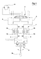
- 12 schematically denotes a hydraulic actuator which is supplied with fluid through a hydraulic directional valve 2 which manages fluid delivery in two directions.
- the directional valve 2 is commanded by a hydraulic joystick 3 provided with a lever 3a, directly activated by the operator.
- the lever 3a controls the travel of the directional valve 2 in order to modulate fluid delivery to the actuator.
- Both the directional valve 2 and the joystick 3 are provided with elastic return systems (in the absence of a manual command) to return the direction valve 2 into a central neutral position.
- two lines 4 and 5 which carry and return the fluid from the joystick to the directional valve 2, and which, according to the direction of movement of the lever 3a, function alternatively as delivery line or return line. All the above-described elements are however of widely known types.
- a cushion circuit denoted in its entirety by 1, is provided between the joystick 3 and the directional valve 2; the cushion circuit controls fluid return from the directional valve 2. Connection between the cushion circuit and the remaining components is obtained through two inlets, respectively V4 located on line 4 and V5 located on line 5, and two outlets, respectively C4 located on line 4 and C5 located on line 5.
- the cushion circuit 1 comprises, on each of the lines 4 and 5, a check valve, respectively 4a located on line 4 and 5a located on line 5, and a pressure compensated flow control valve, relatively 4b located on line 4 and 5b located on line 5.
- the valves are arranged in parallel circuit on the relative line in order that according to need free delivery or controlled return of fluid is obtained.
- the pressure compensated flow control valves 4b and 5b are effectively chokes, and limit the outflow speed through their passage apertures by dint of not allowing flow rates through which are above a certain constant and predetermined limit.
- Each of the check valves 4a and 5a, respectively located on lines 4 and 5, is piloted to open by a pilot pressure, which pilot pressure is constituted by the pressure of the fluid delivered through the check valve on the other line.
- the pilot pressures of the check valves act on the valves through respective pilot pistons 4c and 5c.
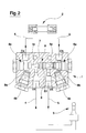
- the cushion is a compact element enclosed in a metal block 6.
- a threaded through-hole 7 is made in the metal block 6, with the check valves 4a and 5a being associated to the ends thereof; the valves 4a and 5a are cartridge-shaped and of known type.
- the valves 4a and 5a are screwed to the ends of the through-hole 7.
- the pilot pistons 4c and 5c are arranged and sealedly calibrated to slide in the central zone of the through-hole 7; in particular, the pilot pistons are made in a single piece S which exhibits a common central zone S1, which is sealedly slidable in the through-hole 7; the pistons 4c and 5c are made on opposite sides of the central portion S1 and interact respectively with the check valve 4a and the check valve 4b to open them.
- Two holes 8a and 8b are afforded in the block 6, having threaded ends to which are associated the pressure compensated flow control valves 4b and 5b, also cartridge-type, of known type and screwed into the respective holes 8a and 8b.
- Two inlet ports V4 and V5 are also afforded in the block 6, as well as two outlet ports C4 and C5 for the fluid; all the ports are arranged on either side of the block 6 with respect to the through-hole 7.
- the inlet port V4, located on the line 4 is directly connected to the through-hole 7 and opens into the through-hole 7 from the posterior part of the pilot piston 5c, in particular in the zone of the through-hole 7 comprised between the common central zone S1 of the element S and the check valve 4a.
- the inlet port V4 is also connected to the outlet port C4 by means of the pressure compensated flow control valve 4b and the check valve 4a.
- the inlet port V5, located on the line 5, is directly connected to the through-hole 7 and opens into the through-hole 7 from the posterior part of the pilot piston 4c, in particular in the zone of the through-hole 7 which is comprised between the common central zone S1 of the element S and the check valve 5a; the inlet port V5 is also connected to the outlet hole C5 by means of the pressure compensated flow control valve 5b and the check valve 5a.
- the device operates as described herein below.
- pressurised fluid is supplied to the line 4; flow-rate pressure on the line 4 causes, obviously, the opening of the check valve 4a present on the line itself, enabling free flow of fluid through the valve 4a; this pilot pressure also pilots the opening of the check valve 5a on the line 5, enabling a free outflow of the fluid and by-passing, in effect, the pressure compensated flow control valve 5b on the line 5.
- the device of the invention enables both check valves to be kept open, constantly by-passing the cushion valve and enabling rapid movements, in both directions, of the slide valve of the directional valve 2, with consequent consecutive rapid movements in both directions of the actuator 12.
- the invention provides a cushion valve that performs operations which in themselves are known, but the circuit layout of the cushion valve is extremely simple and is extremely simple to construct.
Priority Applications (1)
| Application Number | Priority Date | Filing Date | Title |
|---|---|---|---|
| EP03425649A EP1522740A1 (de) | 2003-10-06 | 2003-10-06 | Dämpfungsventil für die hydraulische Steuerung hydraulischer Wegeventile |
Applications Claiming Priority (1)
| Application Number | Priority Date | Filing Date | Title |
|---|---|---|---|
| EP03425649A EP1522740A1 (de) | 2003-10-06 | 2003-10-06 | Dämpfungsventil für die hydraulische Steuerung hydraulischer Wegeventile |
Publications (1)
| Publication Number | Publication Date |
|---|---|
| EP1522740A1 true EP1522740A1 (de) | 2005-04-13 |
Family
ID=34307080
Family Applications (1)
| Application Number | Title | Priority Date | Filing Date |
|---|---|---|---|
| EP03425649A Withdrawn EP1522740A1 (de) | 2003-10-06 | 2003-10-06 | Dämpfungsventil für die hydraulische Steuerung hydraulischer Wegeventile |
Country Status (1)
| Country | Link |
|---|---|
| EP (1) | EP1522740A1 (de) |
Cited By (3)
| Publication number | Priority date | Publication date | Assignee | Title |
|---|---|---|---|---|
| CN106224314A (zh) * | 2016-08-26 | 2016-12-14 | 宁波诚天液压有限公司 | 一种缓冲阀 |
| CN108252972A (zh) * | 2018-01-17 | 2018-07-06 | 邵立坤 | 一种插装式回转缓冲阀 |
| CN108999237A (zh) * | 2018-09-29 | 2018-12-14 | 徐州工程学院 | 一种液压挖掘机用智能控制系统及控制方法 |
Citations (7)
| Publication number | Priority date | Publication date | Assignee | Title |
|---|---|---|---|---|
| US3974742A (en) * | 1974-10-31 | 1976-08-17 | Caterpillar Tractor Co. | Lock valve assembly |
| US4362018A (en) * | 1980-06-12 | 1982-12-07 | Kobe Steel, Ltd. | Hydraulic rotation control circuit |
| EP0281635A1 (de) * | 1986-09-09 | 1988-09-14 | Hitachi Construction Machinery Co., Ltd. | Ventil |
| JPH04343925A (ja) * | 1991-05-22 | 1992-11-30 | Kubota Corp | バックホウ装置の油圧回路構造 |
| JPH05223105A (ja) * | 1991-12-17 | 1993-08-31 | Hitachi Constr Mach Co Ltd | 油圧パイロット装置 |
| JPH1181391A (ja) * | 1997-09-05 | 1999-03-26 | Komatsu Ltd | 作業機の制振制御装置 |
| JP2002121773A (ja) * | 2000-10-16 | 2002-04-26 | Komatsu Ltd | 油圧ショベルの作業機制振装置 |
-
2003
- 2003-10-06 EP EP03425649A patent/EP1522740A1/de not_active Withdrawn
Patent Citations (7)
| Publication number | Priority date | Publication date | Assignee | Title |
|---|---|---|---|---|
| US3974742A (en) * | 1974-10-31 | 1976-08-17 | Caterpillar Tractor Co. | Lock valve assembly |
| US4362018A (en) * | 1980-06-12 | 1982-12-07 | Kobe Steel, Ltd. | Hydraulic rotation control circuit |
| EP0281635A1 (de) * | 1986-09-09 | 1988-09-14 | Hitachi Construction Machinery Co., Ltd. | Ventil |
| JPH04343925A (ja) * | 1991-05-22 | 1992-11-30 | Kubota Corp | バックホウ装置の油圧回路構造 |
| JPH05223105A (ja) * | 1991-12-17 | 1993-08-31 | Hitachi Constr Mach Co Ltd | 油圧パイロット装置 |
| JPH1181391A (ja) * | 1997-09-05 | 1999-03-26 | Komatsu Ltd | 作業機の制振制御装置 |
| JP2002121773A (ja) * | 2000-10-16 | 2002-04-26 | Komatsu Ltd | 油圧ショベルの作業機制振装置 |
Non-Patent Citations (2)
| Title |
|---|
| PATENT ABSTRACTS OF JAPAN vol. 017, no. 671 (M - 1525) 10 December 1993 (1993-12-10) * |
| PATENT ABSTRACTS OF JAPAN vol. 2002, no. 08 5 August 2002 (2002-08-05) * |
Cited By (5)
| Publication number | Priority date | Publication date | Assignee | Title |
|---|---|---|---|---|
| CN106224314A (zh) * | 2016-08-26 | 2016-12-14 | 宁波诚天液压有限公司 | 一种缓冲阀 |
| CN106224314B (zh) * | 2016-08-26 | 2018-06-05 | 宁波诚天液压有限公司 | 一种缓冲阀 |
| CN108252972A (zh) * | 2018-01-17 | 2018-07-06 | 邵立坤 | 一种插装式回转缓冲阀 |
| CN108999237A (zh) * | 2018-09-29 | 2018-12-14 | 徐州工程学院 | 一种液压挖掘机用智能控制系统及控制方法 |
| CN108999237B (zh) * | 2018-09-29 | 2021-03-05 | 徐州工程学院 | 一种液压挖掘机用智能控制系统及控制方法 |
Similar Documents
| Publication | Publication Date | Title |
|---|---|---|
| JP5265078B2 (ja) | 流量調整器を備えた油圧系統 | |
| JP5297187B2 (ja) | 圧力補償装置を有する油圧システム | |
| KR101820324B1 (ko) | 파이프 레이어용 유압회로 | |
| CN107044144B (zh) | 工程机械的液压驱动装置 | |
| EP2955389B1 (de) | Hydraulisches System mit Energierückgewinnung | |
| US6895852B2 (en) | Apparatus and method for providing reduced hydraulic flow to a plurality of actuatable devices in a pressure compensated hydraulic system | |
| US11078646B2 (en) | Shovel and control valve for shovel | |
| WO2008150386A1 (en) | Hydraulic system having an external pressure compensator | |
| JP2017115992A (ja) | 作業機の油圧システム | |
| JP2564308B2 (ja) | 土工機械の作動部材に対する液体圧制御回路 | |
| RU2700971C2 (ru) | Гидравлическая система, способ управления и машина, содержащая данную гидравлическую систему | |
| EP2910796B1 (de) | Anordnung mit einer Steuerventileinrichtung mit einer Schwimmstellung | |
| GB2294558A (en) | Capacity control device for variable capacity hydraulic pump | |
| EP1522740A1 (de) | Dämpfungsventil für die hydraulische Steuerung hydraulischer Wegeventile | |
| KR20050086826A (ko) | 유압 이중-회로 시스템 | |
| WO2023104331A1 (en) | Hydraulic control system in working machine | |
| KR980009962A (ko) | 작동유 공급장치 | |
| WO2014135285A1 (en) | Regenerative circuit of hydraulic apparatus | |
| EP1558849A1 (de) | Hydraulisches zweikreisbremssystem | |
| US20170108015A1 (en) | Independent Metering Valves with Flow Sharing | |
| JP2000266009A (ja) | アクチュエータ制御装置 | |
| KR200215868Y1 (ko) | 건설중장비의 유압펌프 토출유량제어장치 | |
| CN110778560B (zh) | 致动器控制装置 | |
| KR20190115050A (ko) | 방향 전환 밸브 | |
| KR100198155B1 (ko) | 굴삭기의 아암 작동유 재생장치 |
Legal Events
| Date | Code | Title | Description |
|---|---|---|---|
| PUAI | Public reference made under article 153(3) epc to a published international application that has entered the european phase |
Free format text: ORIGINAL CODE: 0009012 |
|
| AK | Designated contracting states |
Kind code of ref document: A1 Designated state(s): AT BE BG CH CY CZ DE DK EE ES FI FR GB GR HU IE IT LI LU MC NL PT RO SE SI SK TR |
|
| AX | Request for extension of the european patent |
Extension state: AL LT LV MK |
|
| AKX | Designation fees paid | ||
| REG | Reference to a national code |
Ref country code: DE Ref legal event code: 8566 |
|
| STAA | Information on the status of an ep patent application or granted ep patent |
Free format text: STATUS: THE APPLICATION IS DEEMED TO BE WITHDRAWN |
|
| 18D | Application deemed to be withdrawn |
Effective date: 20051014 |