EP1522740A1 - A cushion valve for hydraulic remote controls of hydraulic directional valves - Google Patents
A cushion valve for hydraulic remote controls of hydraulic directional valves Download PDFInfo
- Publication number
- EP1522740A1 EP1522740A1 EP03425649A EP03425649A EP1522740A1 EP 1522740 A1 EP1522740 A1 EP 1522740A1 EP 03425649 A EP03425649 A EP 03425649A EP 03425649 A EP03425649 A EP 03425649A EP 1522740 A1 EP1522740 A1 EP 1522740A1
- Authority
- EP
- European Patent Office
- Prior art keywords
- valve
- line
- fluid
- check valve
- hole
- Prior art date
- Legal status (The legal status is an assumption and is not a legal conclusion. Google has not performed a legal analysis and makes no representation as to the accuracy of the status listed.)
- Withdrawn
Links
- 239000012530 fluid Substances 0.000 claims abstract description 31
- 239000002184 metal Substances 0.000 claims description 4
- 238000010276 construction Methods 0.000 claims description 2
- 238000006073 displacement reaction Methods 0.000 description 2
- 238000010586 diagram Methods 0.000 description 1
- 230000000694 effects Effects 0.000 description 1
- 230000007935 neutral effect Effects 0.000 description 1
Images
Classifications
-
- E—FIXED CONSTRUCTIONS
- E02—HYDRAULIC ENGINEERING; FOUNDATIONS; SOIL SHIFTING
- E02F—DREDGING; SOIL-SHIFTING
- E02F9/00—Component parts of dredgers or soil-shifting machines, not restricted to one of the kinds covered by groups E02F3/00 - E02F7/00
- E02F9/20—Drives; Control devices
- E02F9/22—Hydraulic or pneumatic drives
- E02F9/2203—Arrangements for controlling the attitude of actuators, e.g. speed, floating function
- E02F9/2207—Arrangements for controlling the attitude of actuators, e.g. speed, floating function for reducing or compensating oscillations
-
- F—MECHANICAL ENGINEERING; LIGHTING; HEATING; WEAPONS; BLASTING
- F15—FLUID-PRESSURE ACTUATORS; HYDRAULICS OR PNEUMATICS IN GENERAL
- F15B—SYSTEMS ACTING BY MEANS OF FLUIDS IN GENERAL; FLUID-PRESSURE ACTUATORS, e.g. SERVOMOTORS; DETAILS OF FLUID-PRESSURE SYSTEMS, NOT OTHERWISE PROVIDED FOR
- F15B13/00—Details of servomotor systems ; Valves for servomotor systems
- F15B13/02—Fluid distribution or supply devices characterised by their adaptation to the control of servomotors
- F15B13/04—Fluid distribution or supply devices characterised by their adaptation to the control of servomotors for use with a single servomotor
- F15B13/042—Fluid distribution or supply devices characterised by their adaptation to the control of servomotors for use with a single servomotor operated by fluid pressure
- F15B13/0422—Fluid distribution or supply devices characterised by their adaptation to the control of servomotors for use with a single servomotor operated by fluid pressure with manually-operated pilot valves, e.g. joysticks
Definitions
- the invention is usefully applied in fluid distribution circuits in actuators or hydraulic motors for enactment in particular of lifting and lowering operations of booms of machine tools such as excavators or the like, or for rotation of parts or components of the machines.
- the boom carrying the bucket is activated by means of a hydraulic actuator supplied with fluid through a hydraulic directional valve which manages the fluid delivery in the two directions.
- the directional valve is commanded by a hydraulic joystick, generally provided with a lever which is directly manipulated by the operator.
- the joystick commands the movement of the main directional spool in order to modulate the fluid sent to the actuator.
- a cushion circuit is provided between the joystick and the directional valve for controlling the speed of displacement of the latter, and thus for controlling the speed of the excavator.
- These cushion circuits are provided, on each line bringing fluid from the joystick to the directional valve, with a check valve, through which the fluid is delivered, and a compensated flow check valve (essentially a choke) through which fluid return is effected.
- the two valves are arranged in parallel on each line, as each line can function alternatively either as a delivery or return line, so as to obtain, on each line and according to needs, a free delivery flow rate and a controlled return of the fluid.
- a hydraulic device which enables free discharge of the fluid coming from the main spool valve when two-way rapid movement commands are sent to the directional valve.
- These known devices comprise an auxiliary spool, commanded by the existing pressure in the line functioning as the delivery line between the joystick and the main spool, which auxiliary spool enables the flow control valve to be by-passed and discharge of the fluid coming from the main spool to be made directly; it is thus possible to make rapid alternating two-way movements of the main spool, and consequently the actuator and the machine operated thereby.
- a drawback of the above-described solution is that the realization thereof is complex and requires the inclusion of an auxiliary spool; and in turn the auxiliary valve requires oil-inlet lines and sometimes even an additional line of its own for direct fluid discharge, with a consequent complication in the hydraulic pipe system of the machine.
- the main aim of the present invention is to provide a cushion valve for hydraulic remote controls which can obviate the above-mentioned drawback in the prior art, i.e. by simplifying the realization of the cushion valves and the hydraulic circuits connected thereto.
- An advantage of the invention is that it provides a construction system which is particularly simple and compact for the cushion valve.
- 12 schematically denotes a hydraulic actuator which is supplied with fluid through a hydraulic directional valve 2 which manages fluid delivery in two directions.
- the directional valve 2 is commanded by a hydraulic joystick 3 provided with a lever 3a, directly activated by the operator.
- the lever 3a controls the travel of the directional valve 2 in order to modulate fluid delivery to the actuator.
- Both the directional valve 2 and the joystick 3 are provided with elastic return systems (in the absence of a manual command) to return the direction valve 2 into a central neutral position.
- two lines 4 and 5 which carry and return the fluid from the joystick to the directional valve 2, and which, according to the direction of movement of the lever 3a, function alternatively as delivery line or return line. All the above-described elements are however of widely known types.
- a cushion circuit denoted in its entirety by 1, is provided between the joystick 3 and the directional valve 2; the cushion circuit controls fluid return from the directional valve 2. Connection between the cushion circuit and the remaining components is obtained through two inlets, respectively V4 located on line 4 and V5 located on line 5, and two outlets, respectively C4 located on line 4 and C5 located on line 5.
- the cushion circuit 1 comprises, on each of the lines 4 and 5, a check valve, respectively 4a located on line 4 and 5a located on line 5, and a pressure compensated flow control valve, relatively 4b located on line 4 and 5b located on line 5.
- the valves are arranged in parallel circuit on the relative line in order that according to need free delivery or controlled return of fluid is obtained.
- the pressure compensated flow control valves 4b and 5b are effectively chokes, and limit the outflow speed through their passage apertures by dint of not allowing flow rates through which are above a certain constant and predetermined limit.
- Each of the check valves 4a and 5a, respectively located on lines 4 and 5, is piloted to open by a pilot pressure, which pilot pressure is constituted by the pressure of the fluid delivered through the check valve on the other line.
- the pilot pressures of the check valves act on the valves through respective pilot pistons 4c and 5c.
- the cushion is a compact element enclosed in a metal block 6.
- a threaded through-hole 7 is made in the metal block 6, with the check valves 4a and 5a being associated to the ends thereof; the valves 4a and 5a are cartridge-shaped and of known type.
- the valves 4a and 5a are screwed to the ends of the through-hole 7.
- the pilot pistons 4c and 5c are arranged and sealedly calibrated to slide in the central zone of the through-hole 7; in particular, the pilot pistons are made in a single piece S which exhibits a common central zone S1, which is sealedly slidable in the through-hole 7; the pistons 4c and 5c are made on opposite sides of the central portion S1 and interact respectively with the check valve 4a and the check valve 4b to open them.
- Two holes 8a and 8b are afforded in the block 6, having threaded ends to which are associated the pressure compensated flow control valves 4b and 5b, also cartridge-type, of known type and screwed into the respective holes 8a and 8b.
- Two inlet ports V4 and V5 are also afforded in the block 6, as well as two outlet ports C4 and C5 for the fluid; all the ports are arranged on either side of the block 6 with respect to the through-hole 7.
- the inlet port V4, located on the line 4 is directly connected to the through-hole 7 and opens into the through-hole 7 from the posterior part of the pilot piston 5c, in particular in the zone of the through-hole 7 comprised between the common central zone S1 of the element S and the check valve 4a.
- the inlet port V4 is also connected to the outlet port C4 by means of the pressure compensated flow control valve 4b and the check valve 4a.
- the inlet port V5, located on the line 5, is directly connected to the through-hole 7 and opens into the through-hole 7 from the posterior part of the pilot piston 4c, in particular in the zone of the through-hole 7 which is comprised between the common central zone S1 of the element S and the check valve 5a; the inlet port V5 is also connected to the outlet hole C5 by means of the pressure compensated flow control valve 5b and the check valve 5a.
- the device operates as described herein below.
- pressurised fluid is supplied to the line 4; flow-rate pressure on the line 4 causes, obviously, the opening of the check valve 4a present on the line itself, enabling free flow of fluid through the valve 4a; this pilot pressure also pilots the opening of the check valve 5a on the line 5, enabling a free outflow of the fluid and by-passing, in effect, the pressure compensated flow control valve 5b on the line 5.
- the device of the invention enables both check valves to be kept open, constantly by-passing the cushion valve and enabling rapid movements, in both directions, of the slide valve of the directional valve 2, with consequent consecutive rapid movements in both directions of the actuator 12.
- the invention provides a cushion valve that performs operations which in themselves are known, but the circuit layout of the cushion valve is extremely simple and is extremely simple to construct.
Abstract
A cushion valve is applied to a directional valve (2) of known type, and
comprises, on each line (4, 5) which takes fluid from the joystick (3) to the
directional valve (2), a check valve (4a, 5a) and a pressure compensated flow
control valve (4b, 5b) arranged in parallel on a relative line (4, 5) in order to
obtain, on each line, according to circumstances, free delivery and controlled
return of the fluid; each check valve (4a, 5a) located on a line (4, 5) being
piloted to open by a pilot pressure constituted by a fluid pressure entering the
check valve present on another line (4, 5).
Description
- Specifically, though not exclusively, the invention is usefully applied in fluid distribution circuits in actuators or hydraulic motors for enactment in particular of lifting and lowering operations of booms of machine tools such as excavators or the like, or for rotation of parts or components of the machines. In excavators, the boom carrying the bucket is activated by means of a hydraulic actuator supplied with fluid through a hydraulic directional valve which manages the fluid delivery in the two directions. The directional valve is commanded by a hydraulic joystick, generally provided with a lever which is directly manipulated by the operator. The joystick commands the movement of the main directional spool in order to modulate the fluid sent to the actuator. A cushion circuit is provided between the joystick and the directional valve for controlling the speed of displacement of the latter, and thus for controlling the speed of the excavator. These cushion circuits are provided, on each line bringing fluid from the joystick to the directional valve, with a check valve, through which the fluid is delivered, and a compensated flow check valve (essentially a choke) through which fluid return is effected. The two valves are arranged in parallel on each line, as each line can function alternatively either as a delivery or return line, so as to obtain, on each line and according to needs, a free delivery flow rate and a controlled return of the fluid.
- In machine tools, for example excavators, it is often necessary to make rapid out-and-in movements of the boom in order to carry out certain operations, such as for example a rapid movement of the bucket of an excavator when pressing down underlying earth, which is achieved through rapid up and down movements of the excavator boom. The cushion valve, as described above, does not allow for such rapid movements, and therefore the overall performance of the machine is limited.
- To solve this problem the prior art teaches a hydraulic device which enables free discharge of the fluid coming from the main spool valve when two-way rapid movement commands are sent to the directional valve. These known devices comprise an auxiliary spool, commanded by the existing pressure in the line functioning as the delivery line between the joystick and the main spool, which auxiliary spool enables the flow control valve to be by-passed and discharge of the fluid coming from the main spool to be made directly; it is thus possible to make rapid alternating two-way movements of the main spool, and consequently the actuator and the machine operated thereby.
- A drawback of the above-described solution is that the realization thereof is complex and requires the inclusion of an auxiliary spool; and in turn the auxiliary valve requires oil-inlet lines and sometimes even an additional line of its own for direct fluid discharge, with a consequent complication in the hydraulic pipe system of the machine.
- The main aim of the present invention is to provide a cushion valve for hydraulic remote controls which can obviate the above-mentioned drawback in the prior art, i.e. by simplifying the realization of the cushion valves and the hydraulic circuits connected thereto.
- An advantage of the invention is that it provides a construction system which is particularly simple and compact for the cushion valve.
- These aims and advantages and more besides are all attained by the present invention, as it is characterised in the appended claims.
- Further characteristics and advantages of the present invention will better emerge from the detailed description that follows of a preferred but non-exclusive embodiment of the invention, illustrated purely by way of a nonlimiting example in the accompanying figures of the drawings, in which:
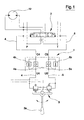
- figure 1 is a diagram of the cushion valve applied to a known-type hydraulic remote control;
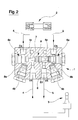
- figure 2 is a section view of a possible constructional realization of the cushion valve.
-
- With reference to figure 1 of the drawings, 12 schematically denotes a hydraulic actuator which is supplied with fluid through a hydraulic
directional valve 2 which manages fluid delivery in two directions. Thedirectional valve 2 is commanded by ahydraulic joystick 3 provided with alever 3a, directly activated by the operator. Thelever 3a controls the travel of thedirectional valve 2 in order to modulate fluid delivery to the actuator. Both thedirectional valve 2 and thejoystick 3 are provided with elastic return systems (in the absence of a manual command) to return thedirection valve 2 into a central neutral position. Also provided are twolines directional valve 2, and which, according to the direction of movement of thelever 3a, function alternatively as delivery line or return line. All the above-described elements are however of widely known types. - A cushion circuit, denoted in its entirety by 1, is provided between the
joystick 3 and thedirectional valve 2; the cushion circuit controls fluid return from thedirectional valve 2. Connection between the cushion circuit and the remaining components is obtained through two inlets, respectively V4 located online 4 and V5 located online 5, and two outlets, respectively C4 located online 4 and C5 located online 5. - The
cushion circuit 1 comprises, on each of thelines line line 5, and a pressure compensated flow control valve, relatively 4b located online line 5. The valves are arranged in parallel circuit on the relative line in order that according to need free delivery or controlled return of fluid is obtained. The pressure compensatedflow control valves - Each of the
check valves lines respective pilot pistons - As can be seen in figure 2, the cushion is a compact element enclosed in a
metal block 6. - A threaded through-hole 7 is made in the
metal block 6, with thecheck valves valves valves pilot pistons pistons check valve 4a and thecheck valve 4b to open them. - Two
holes block 6, having threaded ends to which are associated the pressure compensatedflow control valves respective holes - Two inlet ports V4 and V5 are also afforded in the
block 6, as well as two outlet ports C4 and C5 for the fluid; all the ports are arranged on either side of theblock 6 with respect to the through-hole 7. - The inlet port V4, located on the
line 4, is directly connected to the through-hole 7 and opens into the through-hole 7 from the posterior part of thepilot piston 5c, in particular in the zone of the through-hole 7 comprised between the common central zone S1 of the element S and thecheck valve 4a. The inlet port V4 is also connected to the outlet port C4 by means of the pressure compensatedflow control valve 4b and thecheck valve 4a. - The inlet port V5, located on the
line 5, is directly connected to the through-hole 7 and opens into the through-hole 7 from the posterior part of thepilot piston 4c, in particular in the zone of the through-hole 7 which is comprised between the common central zone S1 of the element S and thecheck valve 5a; the inlet port V5 is also connected to the outlet hole C5 by means of the pressure compensatedflow control valve 5b and thecheck valve 5a. - The device operates as described herein below.
- By switching the
lever 3a, for example leftwards with reference to figure 1, pressurised fluid is supplied to theline 4; flow-rate pressure on theline 4 causes, obviously, the opening of thecheck valve 4a present on the line itself, enabling free flow of fluid through thevalve 4a; this pilot pressure also pilots the opening of thecheck valve 5a on theline 5, enabling a free outflow of the fluid and by-passing, in effect, the pressure compensatedflow control valve 5b on theline 5. - By bringing the
lever 3a into the central position, fluid delivery to theline 4 is stopped; thedirectional valve 2 is returned (by the elastic elements it is provided with) into the central position with a gradual action due to the fact that the fluid slowly discharges from theline 5 through the pressure compensatedflow control valve 5b. - Obviously the above-described sequences are repeated, in inverted direction, displacing the
lever 3 a towards the right (see figure 1) instead of the left. - If it is wished to make rapid out and in movements, obtainable with rapid and consecutive displacements of the
lever 3a from right to left without stopping it in the central closed position, the device of the invention enables both check valves to be kept open, constantly by-passing the cushion valve and enabling rapid movements, in both directions, of the slide valve of thedirectional valve 2, with consequent consecutive rapid movements in both directions of theactuator 12. - The invention provides a cushion valve that performs operations which in themselves are known, but the circuit layout of the cushion valve is extremely simple and is extremely simple to construct.
Claims (4)
- A cushion valve for hydraulic remote controls of hydraulic directional valves, of a type applicable to a known-type directional valve (2), controlled by a hydraulic joystick (3) of known type and comprising, on each of lines (4, 5) delivering a fluid from the joystick (3) to the directional valve (2), a check valve (4a, 5a) and a pressure compensated flow control valve (4b, 5b) arranged in parallel on each line of the lines (4, 5) in order to obtain on each line of the lines (4, 5), according to need, a free delivery and a controlled return of the fluid, characterised in that each check valve (4a, 5a) located on each line of the lines (4, 5) is opened by a pilot pressure constituted by a pressure of the fluid entering another check valve (4a, 5a) present on another line of the lines (4, 5).
- The cushion valve of claim 1, characterised in that the pilot pressures act on the check valves (4a, 5a) through a pilot piston (4c, 5c); the check valves (4a, 5a) and pressure compensated flow control valves (4b, 5b) being of known type cartridge-construction.
- The cushion valve of claim 2, characterised in that it comprises a metal block (6) affording a through-hole (7) having threaded ends, to which ends are associated the check valves (4a, 5a), the pilot pistons (4c, 5c) being sealedly calibrated and slidable in a central portion of the through-hole (7); the metal block (6) further affording two holes (8a, 8b) having threaded ends to which threaded ends are connected the pressure compensated flow control valves (4b, 5b); two inlet ports (V4, V5) and two outlet ports (C4, C5) for the fluid being arranged on either side of the through-hole (7), the inlet port (V4) being directly connected to the through-hole (7) at a posterior part of the pilot piston (5c) and, through the pressure compensated flow control valve (4b) and the check valve (4a), to the outlet port (C4); the inlet port (V5) being directly connected at the through-hole (7) at a posterior part of the pilot piston (4c) and, through the pressure compensated flow control valve (5b) and the check valve (5a), to the outlet port (C5).
- The cushion valve of claim 3, characterised in that the pilot pistons (4c, 5c) are made in a single piece (S) having a common central zone (S1), sealedly calibrated and slidable in the through-hole (7), on opposite sides of which the pistons (4c, 5c) are fashioned, which pistons (4c, 5c) interact respectively with the check valve (4a) and the check valve (5a).
Priority Applications (1)
| Application Number | Priority Date | Filing Date | Title |
|---|---|---|---|
| EP03425649A EP1522740A1 (en) | 2003-10-06 | 2003-10-06 | A cushion valve for hydraulic remote controls of hydraulic directional valves |
Applications Claiming Priority (1)
| Application Number | Priority Date | Filing Date | Title |
|---|---|---|---|
| EP03425649A EP1522740A1 (en) | 2003-10-06 | 2003-10-06 | A cushion valve for hydraulic remote controls of hydraulic directional valves |
Publications (1)
| Publication Number | Publication Date |
|---|---|
| EP1522740A1 true EP1522740A1 (en) | 2005-04-13 |
Family
ID=34307080
Family Applications (1)
| Application Number | Title | Priority Date | Filing Date |
|---|---|---|---|
| EP03425649A Withdrawn EP1522740A1 (en) | 2003-10-06 | 2003-10-06 | A cushion valve for hydraulic remote controls of hydraulic directional valves |
Country Status (1)
| Country | Link |
|---|---|
| EP (1) | EP1522740A1 (en) |
Cited By (3)
| Publication number | Priority date | Publication date | Assignee | Title |
|---|---|---|---|---|
| CN106224314A (en) * | 2016-08-26 | 2016-12-14 | 宁波诚天液压有限公司 | A kind of trimmer valve |
| CN108252972A (en) * | 2018-01-17 | 2018-07-06 | 邵立坤 | A kind of plug-in rotary buffering valve |
| CN108999237A (en) * | 2018-09-29 | 2018-12-14 | 徐州工程学院 | A kind of hydraulic crawler excavator intelligence control system and control method |
Citations (7)
| Publication number | Priority date | Publication date | Assignee | Title |
|---|---|---|---|---|
| US3974742A (en) * | 1974-10-31 | 1976-08-17 | Caterpillar Tractor Co. | Lock valve assembly |
| US4362018A (en) * | 1980-06-12 | 1982-12-07 | Kobe Steel, Ltd. | Hydraulic rotation control circuit |
| EP0281635A1 (en) * | 1986-09-09 | 1988-09-14 | Hitachi Construction Machinery Co., Ltd. | Valve device |
| JPH04343925A (en) * | 1991-05-22 | 1992-11-30 | Kubota Corp | Hydraulic circuit structure for back hoe device |
| JPH05223105A (en) * | 1991-12-17 | 1993-08-31 | Hitachi Constr Mach Co Ltd | Oil pressure pilot device |
| JPH1181391A (en) * | 1997-09-05 | 1999-03-26 | Komatsu Ltd | Vibration controller for working machine |
| JP2002121773A (en) * | 2000-10-16 | 2002-04-26 | Komatsu Ltd | Work machine damping device for hydraulic excavator |
-
2003
- 2003-10-06 EP EP03425649A patent/EP1522740A1/en not_active Withdrawn
Patent Citations (7)
| Publication number | Priority date | Publication date | Assignee | Title |
|---|---|---|---|---|
| US3974742A (en) * | 1974-10-31 | 1976-08-17 | Caterpillar Tractor Co. | Lock valve assembly |
| US4362018A (en) * | 1980-06-12 | 1982-12-07 | Kobe Steel, Ltd. | Hydraulic rotation control circuit |
| EP0281635A1 (en) * | 1986-09-09 | 1988-09-14 | Hitachi Construction Machinery Co., Ltd. | Valve device |
| JPH04343925A (en) * | 1991-05-22 | 1992-11-30 | Kubota Corp | Hydraulic circuit structure for back hoe device |
| JPH05223105A (en) * | 1991-12-17 | 1993-08-31 | Hitachi Constr Mach Co Ltd | Oil pressure pilot device |
| JPH1181391A (en) * | 1997-09-05 | 1999-03-26 | Komatsu Ltd | Vibration controller for working machine |
| JP2002121773A (en) * | 2000-10-16 | 2002-04-26 | Komatsu Ltd | Work machine damping device for hydraulic excavator |
Non-Patent Citations (2)
| Title |
|---|
| PATENT ABSTRACTS OF JAPAN vol. 017, no. 671 (M - 1525) 10 December 1993 (1993-12-10) * |
| PATENT ABSTRACTS OF JAPAN vol. 2002, no. 08 5 August 2002 (2002-08-05) * |
Cited By (5)
| Publication number | Priority date | Publication date | Assignee | Title |
|---|---|---|---|---|
| CN106224314A (en) * | 2016-08-26 | 2016-12-14 | 宁波诚天液压有限公司 | A kind of trimmer valve |
| CN106224314B (en) * | 2016-08-26 | 2018-06-05 | 宁波诚天液压有限公司 | A kind of trimmer valve |
| CN108252972A (en) * | 2018-01-17 | 2018-07-06 | 邵立坤 | A kind of plug-in rotary buffering valve |
| CN108999237A (en) * | 2018-09-29 | 2018-12-14 | 徐州工程学院 | A kind of hydraulic crawler excavator intelligence control system and control method |
| CN108999237B (en) * | 2018-09-29 | 2021-03-05 | 徐州工程学院 | Intelligent control system and control method for hydraulic excavator |
Similar Documents
| Publication | Publication Date | Title |
|---|---|---|
| JP5265078B2 (en) | Hydraulic system with flow regulator | |
| JP5297187B2 (en) | Hydraulic system with pressure compensator | |
| KR101820324B1 (en) | Hydraulic circuit for pipe layer | |
| CN107044144B (en) | Hydraulic drive device for construction machine | |
| EP2955389B1 (en) | Hydraulic system with energy recovery | |
| RU2698149C2 (en) | Machine hydraulic system and machine | |
| US6895852B2 (en) | Apparatus and method for providing reduced hydraulic flow to a plurality of actuatable devices in a pressure compensated hydraulic system | |
| US11078646B2 (en) | Shovel and control valve for shovel | |
| JP2017115992A (en) | Hydraulic system of work machine | |
| JP2564308B2 (en) | Liquid pressure control circuit for working members of earthmoving machinery | |
| RU2700971C2 (en) | Hydraulic system, control method and machine comprising said hydraulic system | |
| GB2294558A (en) | Capacity control device for variable capacity hydraulic pump | |
| EP1522740A1 (en) | A cushion valve for hydraulic remote controls of hydraulic directional valves | |
| EP2910796B1 (en) | Assembly with a control valve device with a float position | |
| KR20050086826A (en) | Hydraulic dual circuit system | |
| WO2023104331A1 (en) | Hydraulic control system in working machine | |
| KR980009962A (en) | Hydraulic oil supply | |
| WO2014135285A1 (en) | Regenerative circuit of hydraulic apparatus | |
| EP1558849A1 (en) | Double-circuit hydraulic system | |
| US20170108015A1 (en) | Independent Metering Valves with Flow Sharing | |
| JP2000266009A (en) | Actuator controller | |
| KR200215868Y1 (en) | Hydraulic pump discharge flow control device for construction equipment | |
| CN110778560B (en) | Actuator control device | |
| KR20190115050A (en) | Directional valve | |
| KR100198155B1 (en) | Arm working oil remaking device of excavator |
Legal Events
| Date | Code | Title | Description |
|---|---|---|---|
| PUAI | Public reference made under article 153(3) epc to a published international application that has entered the european phase |
Free format text: ORIGINAL CODE: 0009012 |
|
| AK | Designated contracting states |
Kind code of ref document: A1 Designated state(s): AT BE BG CH CY CZ DE DK EE ES FI FR GB GR HU IE IT LI LU MC NL PT RO SE SI SK TR |
|
| AX | Request for extension of the european patent |
Extension state: AL LT LV MK |
|
| AKX | Designation fees paid | ||
| REG | Reference to a national code |
Ref country code: DE Ref legal event code: 8566 |
|
| STAA | Information on the status of an ep patent application or granted ep patent |
Free format text: STATUS: THE APPLICATION IS DEEMED TO BE WITHDRAWN |
|
| 18D | Application deemed to be withdrawn |
Effective date: 20051014 |