EP1522704B1 - Zylinderblock für eine Brennkraftmaschine - Google Patents
Zylinderblock für eine Brennkraftmaschine Download PDFInfo
- Publication number
- EP1522704B1 EP1522704B1 EP04023252A EP04023252A EP1522704B1 EP 1522704 B1 EP1522704 B1 EP 1522704B1 EP 04023252 A EP04023252 A EP 04023252A EP 04023252 A EP04023252 A EP 04023252A EP 1522704 B1 EP1522704 B1 EP 1522704B1
- Authority
- EP
- European Patent Office
- Prior art keywords
- cylinder
- cylinder block
- wall
- jacket
- walls
- Prior art date
- Legal status (The legal status is an assumption and is not a legal conclusion. Google has not performed a legal analysis and makes no representation as to the accuracy of the status listed.)
- Expired - Lifetime
Links
- 238000002485 combustion reaction Methods 0.000 title claims description 14
- XLYOFNOQVPJJNP-UHFFFAOYSA-N water Substances O XLYOFNOQVPJJNP-UHFFFAOYSA-N 0.000 claims description 26
- 230000003014 reinforcing effect Effects 0.000 claims description 11
- 238000010276 construction Methods 0.000 claims description 6
- 230000002093 peripheral effect Effects 0.000 claims description 5
- 239000000498 cooling water Substances 0.000 description 4
- 238000010438 heat treatment Methods 0.000 description 4
- 239000000446 fuel Substances 0.000 description 3
- XAGFODPZIPBFFR-UHFFFAOYSA-N aluminium Chemical compound [Al] XAGFODPZIPBFFR-UHFFFAOYSA-N 0.000 description 2
- 229910052782 aluminium Inorganic materials 0.000 description 2
- 238000001816 cooling Methods 0.000 description 2
- 230000001629 suppression Effects 0.000 description 2
- 239000013585 weight reducing agent Substances 0.000 description 2
- 230000004323 axial length Effects 0.000 description 1
- 230000001419 dependent effect Effects 0.000 description 1
- 239000000203 mixture Substances 0.000 description 1
Images


Classifications
-
- F—MECHANICAL ENGINEERING; LIGHTING; HEATING; WEAPONS; BLASTING
- F02—COMBUSTION ENGINES; HOT-GAS OR COMBUSTION-PRODUCT ENGINE PLANTS
- F02F—CYLINDERS, PISTONS OR CASINGS, FOR COMBUSTION ENGINES; ARRANGEMENTS OF SEALINGS IN COMBUSTION ENGINES
- F02F7/00—Casings, e.g. crankcases
- F02F7/0002—Cylinder arrangements
- F02F7/0007—Crankcases of engines with cylinders in line
Definitions
- the present invention relates to a cylinder blocks of an internal combustion engine according to the preamble of independent claim 1.
- a cylinder blocks is of a so-called shallow bottom water jacket type wherein a bottom of a water jacket surrounding each cylinder is positioned above a lower deck portion of the cylinder block.
- Such a cylinder block is known from the prior art document US 4,515,112 .
- crank case 24 As is seen from Figs. 1 and 2, from lower deck portion 22, there extends downward a crank case 24.
- crank case 24 comprises a plurality of bearing cap mounting walls 26 that rotatably support a crankshaft with the aid of bearing caps (not shown).
- a jacket bottom wall 16 defining therein a bottom surface of water jacket 18 extends between a lower end of each jacket side wall 14 and a middle portion of the corresponding cylinder wall 12. With this, jacket bottom wall 16 is positioned above lower deck portion 22, so that water jacket 18 is formed about only an upper part of each cylinder wall 12. That is, the shallow bottom water jacket 18 is provided.
Landscapes
- Engineering & Computer Science (AREA)
- Chemical & Material Sciences (AREA)
- Combustion & Propulsion (AREA)
- Mechanical Engineering (AREA)
- General Engineering & Computer Science (AREA)
- Cylinder Crankcases Of Internal Combustion Engines (AREA)
Claims (9)
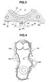
- Zylinderblock einer Brennkraftmaschine, aufweisend:einen oberen Deckabschnitt (20), auf dem ein Zylinderkopf montiert werden soll; einen unteren Deckabschnitt (22), von dem sich ein Kurbelgehäuse (24) abwärts erstreckt; ausgerichtete Zylinderwände (12), die sich jeweils vertikal zwischendem oberen und unteren Deckabschnitt (20, 22) erstrecken, wobei die Zylinderwände (12) jeweils darin gebildete Zylinderbohrungen (11) begrenzen; Mantelseitenwände (14) jeweils die Zylinderwände (12) umgeben, so dass ein Wassermantel (18) zwischen jeder Mantelseitenwand (14) und der entsprechenden Zylinderwand (12) gebildet wird;Mantelbodenwände (16), die sich jeweils zwischen einem vertikalen untersten Ende von jeder Mantelseitenwand (14) und einem vertikalen Mittelteil der entsprechenden Zylinderwand (12) erstrecken, wobei die Mantelbodenwände (16) oberhalb des unteren Deckabschnittes (22) positioniert sind;eine vordere Wand (28), die eine axiale Endwand des Zylinderblocks (10) bildet, wobei die vordere Wand (28) mit einem vorderen Teil des oberen Deckabschnittes (20), einem vorderen Teil des unteren Deckabschnittes (22), einem vorderen der Zylinderwände, einer vorderen der Mantelseitenwände (14) und einer vorderen der Mantelbodenwände (16) einstückig ist;gekennzeichnet durcheine Verstärkungsanordnung, einstückig gebildet an der vorderen Wand (28) zum Verstärken einer gesamten Konstruktion des Zylinderblocks (10), wobei die Verstärkungsanordnung von einem Typ ist, der sich von einer Hauptoberfläche der vorderen Wand erhebt, wobei die Verstärkungsanordnung sich wechselseitig kreuzende vertikale und seitliche Rippen (42, 44) aufweist, wobei sich die vertikale Rippe (42) zwischen dem oberen Deckabschnitt (20) und dem unteren Deckabschnitt (22) erstreckt und die seitliche Rippe (44) eine angehobene Kante der vorderen der Mantelbodenwände (16) bildet.
- Zylinderblock nach Anspruch 1, dadurch gekennzeichnet, dass die Verstärkungsanordnung außerdem zwei Kopfschraubennaben (36a, 36b) aufweist, die an der vorderen Wand (28) einstückig gebildet sind, wobei jede Kopfschraubennabe (36a, 36b) aufgebaut ist, eine Kopfschraube zum Befestigen des Zylinderkopfes an dem oberen Deckabschnitt (20) zu erfassen.
- Zylinderblock nach Anspruch 2, dadurch gekennzeichnet, dass die Kopfschraubennaben (36a, 36b) jeweils untere Enden haben, zwischen denen sich die seitliche Rippe (44) erstreckt.
- Zylinderblock nach zumindest einem der Ansprüche 1 bis 3, dadurch gekennzeichnet, dass die vertikalen und seitlichen Rippen (42, 44) an ihrem Kreuzungsabschnitt eine Schraubennabe (46) aufweisen, die aufgebaut ist, um eine Verbindungsschraube zu erfassen, die zum Befestigen eines Mittelabschnittes einer vorderen Abdeckung (38) an der vorderen Wand (28) verwendet wird.
- Zylinderblock nach Anspruch 4, dadurch gekennzeichnet, dass die vordere Wand (28) an ihrem Umfängsabschnitt mit einer Mehrzahl von Schraubenbohrungen (36) gebildet ist, die aufgebaut sind, die Verbindungsschrauben, verwendet zum Befestigen eines Umfangsabschnittes der vorderen Abdeckung (38) an der vorderen Wand (28), zu erfassen.
- Zylinderblock nach zumindest einem der Ansprüche 1 bis 5, dadurch gekennzeichnet, dass sich die vertikale Rippe (42) entlang einer gedachten Ebene "L1", auf der die Achsen der Zylinderbohrungen (11) liegen, erstreckt.
- Zylinderblock nach zumindest einem der Ansprüche 1 bis 6, dadurch gekennzeichnet, dass die Verstärkungsanordnung eine angehobene Schraubennabe (46) aufweist, die einstückig an der vorderen der Mantelbodenwände (16) gebildet ist, um eine Verbindungsschraube, verwendet zum Befestigen eines Mittelabschnittes einer vorderen Abdeckung (38) an der vorderen Wand (28), zu erfassen.
- Zylinderblock nach Anspruch 7, dadurch gekennzeichnet, dass die angehobene Schraubennabe (46) auf einer gedachten Ebene positioniert ist, auf der die jeweiligen Achsen der Zylinderbohrungen (11) liegen.
- Zylinderblock nach Anspruch 8, dadurch gekennzeichnet, dass die angehobene Schraubennabe (46) angeordnet ist, um einen im Wesentlichen Mittelabschnitt einer vorderen Abdeckung (38) daran mittels einer Verbindungsschraube zu verbinden.
Applications Claiming Priority (2)
| Application Number | Priority Date | Filing Date | Title |
|---|---|---|---|
| JP2003351586A JP4196803B2 (ja) | 2003-10-10 | 2003-10-10 | 内燃機関のシリンダブロック |
| JP2003351586 | 2003-10-10 |
Publications (2)
| Publication Number | Publication Date |
|---|---|
| EP1522704A1 EP1522704A1 (de) | 2005-04-13 |
| EP1522704B1 true EP1522704B1 (de) | 2007-07-04 |
Family
ID=34309273
Family Applications (1)
| Application Number | Title | Priority Date | Filing Date |
|---|---|---|---|
| EP04023252A Expired - Lifetime EP1522704B1 (de) | 2003-10-10 | 2004-09-29 | Zylinderblock für eine Brennkraftmaschine |
Country Status (5)
| Country | Link |
|---|---|
| US (1) | US7077079B2 (de) |
| EP (1) | EP1522704B1 (de) |
| JP (1) | JP4196803B2 (de) |
| CN (1) | CN100591908C (de) |
| DE (1) | DE602004007339T2 (de) |
Families Citing this family (4)
| Publication number | Priority date | Publication date | Assignee | Title |
|---|---|---|---|---|
| EP1699512B1 (de) | 2003-11-03 | 2012-06-20 | Glaxo Group Limited | Fluidabgabevorrichtung |
| JP4187045B2 (ja) * | 2007-03-16 | 2008-11-26 | トヨタ自動車株式会社 | シリンダブロック |
| CN101956622B (zh) * | 2010-10-31 | 2012-05-23 | 无锡开普动力有限公司 | 一种直列水冷发动机机体 |
| JP6009104B2 (ja) * | 2013-12-27 | 2016-10-19 | 愛知機械工業株式会社 | シリンダブロック及び内燃機関 |
Family Cites Families (10)
| Publication number | Priority date | Publication date | Assignee | Title |
|---|---|---|---|---|
| JPS5816334U (ja) * | 1973-06-21 | 1983-02-01 | ナシヨナル リサ−チ デベロツプメント コ−ポレ−シヨン | 内燃機関 |
| US4237847A (en) * | 1979-03-21 | 1980-12-09 | Cummins Engine Company, Inc. | Composite engine block having high strength to weight ratio |
| JPS6313407Y2 (de) * | 1980-10-31 | 1988-04-15 | ||
| JPS5874851A (ja) * | 1981-10-28 | 1983-05-06 | Toyota Motor Corp | アルミニウム合金製シリンダブロツク |
| IT1182082B (it) * | 1984-12-13 | 1987-09-30 | Honda Motor Co Ltd | Struttura di blocco clindri per motore a combustione interna a piu' cilindri |
| JPH0579195U (ja) * | 1992-03-31 | 1993-10-26 | マツダ株式会社 | V型エンジンのベルトカバー取付構造 |
| US5253615A (en) * | 1992-12-24 | 1993-10-19 | Ford Motor Company | Cylinder block cylinder bore isolator |
| JP3079835B2 (ja) * | 1993-04-16 | 2000-08-21 | スズキ株式会社 | シリンダブロック構造 |
| JP3644299B2 (ja) | 1999-04-02 | 2005-04-27 | 日産自動車株式会社 | 水冷式内燃機関のシリンダブロック |
| JP3843724B2 (ja) * | 2000-10-03 | 2006-11-08 | マツダ株式会社 | エンジンのシリンダブロック構造 |
-
2003
- 2003-10-10 JP JP2003351586A patent/JP4196803B2/ja not_active Expired - Lifetime
-
2004
- 2004-09-29 EP EP04023252A patent/EP1522704B1/de not_active Expired - Lifetime
- 2004-09-29 DE DE602004007339T patent/DE602004007339T2/de not_active Expired - Lifetime
- 2004-10-07 US US10/959,577 patent/US7077079B2/en not_active Expired - Lifetime
- 2004-10-10 CN CN200410084939A patent/CN100591908C/zh not_active Expired - Lifetime
Also Published As
| Publication number | Publication date |
|---|---|
| JP2005113855A (ja) | 2005-04-28 |
| CN100591908C (zh) | 2010-02-24 |
| DE602004007339T2 (de) | 2007-10-31 |
| JP4196803B2 (ja) | 2008-12-17 |
| CN1605736A (zh) | 2005-04-13 |
| EP1522704A1 (de) | 2005-04-13 |
| US7077079B2 (en) | 2006-07-18 |
| DE602004007339D1 (de) | 2007-08-16 |
| US20050076861A1 (en) | 2005-04-14 |
Similar Documents
| Publication | Publication Date | Title |
|---|---|---|
| US8474442B2 (en) | Structural oil baffle for engine covers | |
| US5611301A (en) | Structural enclosure of combustion engines for the purpose of reducing engine noise | |
| JP3967552B2 (ja) | エンジン用気液分離装置 | |
| CN106894906B (zh) | 多缸发动机的冷却结构 | |
| JP4258339B2 (ja) | 内燃機関のシリンダブロック | |
| CA1057148A (en) | Cylinder head mounting apparatus for internal combustion engines | |
| JPH07197865A (ja) | V型多気筒エンジンの吸気装置 | |
| EP1522704B1 (de) | Zylinderblock für eine Brennkraftmaschine | |
| US4643137A (en) | Engine construction | |
| KR100523307B1 (ko) | 내연 기관용 실린더 블록 | |
| US5873331A (en) | Cylinder head for a multi-cylinder internal combustion engine | |
| JP4262756B2 (ja) | 多気筒エンジン | |
| EP0208312A2 (de) | Zylinderkopf mit um den Aussenumfang der Befestigungsstützen angeordneten, auf die Quetschzone gerichteten Kühlmittelpassagen | |
| US5743218A (en) | Liquid cooled cylinder head for an internal combustion engine | |
| US6338660B1 (en) | Exhaust system for an outboard motor | |
| JP6399074B2 (ja) | インタークーラ付きエンジンの吸気装置 | |
| JP7332261B2 (ja) | 多気筒内燃機関の本体ブロック | |
| JP2003035229A (ja) | V型エンジンの吸気装置 | |
| US7036479B2 (en) | Cylinder block for engine | |
| JP7456713B2 (ja) | 多気筒内燃機関の本体ブロック | |
| JP2839826B2 (ja) | サイアミーズ型シリンダブロックの構造 | |
| JP3837313B2 (ja) | エンジン | |
| JP3962269B2 (ja) | 多気筒エンジン | |
| JP2025082688A (ja) | エンジン | |
| JP7303492B2 (ja) | エンジン構造 |
Legal Events
| Date | Code | Title | Description |
|---|---|---|---|
| PUAI | Public reference made under article 153(3) epc to a published international application that has entered the european phase |
Free format text: ORIGINAL CODE: 0009012 |
|
| 17P | Request for examination filed |
Effective date: 20040929 |
|
| AK | Designated contracting states |
Kind code of ref document: A1 Designated state(s): AT BE BG CH CY CZ DE DK EE ES FI FR GB GR HU IE IT LI LU MC NL PL PT RO SE SI SK TR |
|
| AX | Request for extension of the european patent |
Extension state: AL HR LT LV MK |
|
| AKX | Designation fees paid |
Designated state(s): DE FR GB |
|
| 17Q | First examination report despatched |
Effective date: 20051103 |
|
| GRAP | Despatch of communication of intention to grant a patent |
Free format text: ORIGINAL CODE: EPIDOSNIGR1 |
|
| GRAS | Grant fee paid |
Free format text: ORIGINAL CODE: EPIDOSNIGR3 |
|
| GRAA | (expected) grant |
Free format text: ORIGINAL CODE: 0009210 |
|
| AK | Designated contracting states |
Kind code of ref document: B1 Designated state(s): DE FR GB |
|
| REG | Reference to a national code |
Ref country code: GB Ref legal event code: FG4D |
|
| REF | Corresponds to: |
Ref document number: 602004007339 Country of ref document: DE Date of ref document: 20070816 Kind code of ref document: P |
|
| ET | Fr: translation filed | ||
| PLBE | No opposition filed within time limit |
Free format text: ORIGINAL CODE: 0009261 |
|
| STAA | Information on the status of an ep patent application or granted ep patent |
Free format text: STATUS: NO OPPOSITION FILED WITHIN TIME LIMIT |
|
| 26N | No opposition filed |
Effective date: 20080407 |
|
| REG | Reference to a national code |
Ref country code: FR Ref legal event code: PLFP Year of fee payment: 13 |
|
| REG | Reference to a national code |
Ref country code: FR Ref legal event code: PLFP Year of fee payment: 14 |
|
| REG | Reference to a national code |
Ref country code: FR Ref legal event code: PLFP Year of fee payment: 15 |
|
| PGFP | Annual fee paid to national office [announced via postgrant information from national office to epo] |
Ref country code: GB Payment date: 20230823 Year of fee payment: 20 |
|
| PGFP | Annual fee paid to national office [announced via postgrant information from national office to epo] |
Ref country code: FR Payment date: 20230822 Year of fee payment: 20 Ref country code: DE Payment date: 20230822 Year of fee payment: 20 |
|
| REG | Reference to a national code |
Ref country code: DE Ref legal event code: R071 Ref document number: 602004007339 Country of ref document: DE |
|
| PG25 | Lapsed in a contracting state [announced via postgrant information from national office to epo] |
Ref country code: GB Free format text: LAPSE BECAUSE OF EXPIRATION OF PROTECTION Effective date: 20240928 |
|
| REG | Reference to a national code |
Ref country code: GB Ref legal event code: PE20 Expiry date: 20240928 |
|
| PG25 | Lapsed in a contracting state [announced via postgrant information from national office to epo] |
Ref country code: GB Free format text: LAPSE BECAUSE OF EXPIRATION OF PROTECTION Effective date: 20240928 |