EP1522704B1 - Cylinder block of internal combustion engine - Google Patents
Cylinder block of internal combustion engine Download PDFInfo
- Publication number
- EP1522704B1 EP1522704B1 EP04023252A EP04023252A EP1522704B1 EP 1522704 B1 EP1522704 B1 EP 1522704B1 EP 04023252 A EP04023252 A EP 04023252A EP 04023252 A EP04023252 A EP 04023252A EP 1522704 B1 EP1522704 B1 EP 1522704B1
- Authority
- EP
- European Patent Office
- Prior art keywords
- cylinder
- cylinder block
- wall
- jacket
- walls
- Prior art date
- Legal status (The legal status is an assumption and is not a legal conclusion. Google has not performed a legal analysis and makes no representation as to the accuracy of the status listed.)
- Expired - Lifetime
Links
- 238000002485 combustion reaction Methods 0.000 title claims description 14
- XLYOFNOQVPJJNP-UHFFFAOYSA-N water Substances O XLYOFNOQVPJJNP-UHFFFAOYSA-N 0.000 claims description 26
- 230000003014 reinforcing effect Effects 0.000 claims description 11
- 238000010276 construction Methods 0.000 claims description 6
- 230000002093 peripheral effect Effects 0.000 claims description 5
- 239000000498 cooling water Substances 0.000 description 4
- 238000010438 heat treatment Methods 0.000 description 4
- 239000000446 fuel Substances 0.000 description 3
- XAGFODPZIPBFFR-UHFFFAOYSA-N aluminium Chemical compound [Al] XAGFODPZIPBFFR-UHFFFAOYSA-N 0.000 description 2
- 229910052782 aluminium Inorganic materials 0.000 description 2
- 238000001816 cooling Methods 0.000 description 2
- 230000001629 suppression Effects 0.000 description 2
- 239000013585 weight reducing agent Substances 0.000 description 2
- 230000004323 axial length Effects 0.000 description 1
- 230000001419 dependent effect Effects 0.000 description 1
- 239000000203 mixture Substances 0.000 description 1
Images


Classifications
-
- F—MECHANICAL ENGINEERING; LIGHTING; HEATING; WEAPONS; BLASTING
- F02—COMBUSTION ENGINES; HOT-GAS OR COMBUSTION-PRODUCT ENGINE PLANTS
- F02F—CYLINDERS, PISTONS OR CASINGS, FOR COMBUSTION ENGINES; ARRANGEMENTS OF SEALINGS IN COMBUSTION ENGINES
- F02F7/00—Casings, e.g. crankcases
- F02F7/0002—Cylinder arrangements
- F02F7/0007—Crankcases of engines with cylinders in line
Definitions
- the present invention relates to a cylinder blocks of an internal combustion engine according to the preamble of independent claim 1.
- a cylinder blocks is of a so-called shallow bottom water jacket type wherein a bottom of a water jacket surrounding each cylinder is positioned above a lower deck portion of the cylinder block.
- Such a cylinder block is known from the prior art document US 4,515,112 .
- crank case 24 As is seen from Figs. 1 and 2, from lower deck portion 22, there extends downward a crank case 24.
- crank case 24 comprises a plurality of bearing cap mounting walls 26 that rotatably support a crankshaft with the aid of bearing caps (not shown).
- a jacket bottom wall 16 defining therein a bottom surface of water jacket 18 extends between a lower end of each jacket side wall 14 and a middle portion of the corresponding cylinder wall 12. With this, jacket bottom wall 16 is positioned above lower deck portion 22, so that water jacket 18 is formed about only an upper part of each cylinder wall 12. That is, the shallow bottom water jacket 18 is provided.
Landscapes
- Engineering & Computer Science (AREA)
- Chemical & Material Sciences (AREA)
- Combustion & Propulsion (AREA)
- Mechanical Engineering (AREA)
- General Engineering & Computer Science (AREA)
- Cylinder Crankcases Of Internal Combustion Engines (AREA)
Description
- The present invention relates to a cylinder blocks of an internal combustion engine according to the preamble of independent claim 1. Such a cylinder blocks is of a so-called shallow bottom water jacket type wherein a bottom of a water jacket surrounding each cylinder is positioned above a lower deck portion of the cylinder block. Such a cylinder block is known from the prior art document
US 4,515,112 . -
Japanese Laid-open Patent Application (Tokkaihei) 6-299900 Japanese Laid-open Patent Application 2000-291488 - With the shallow bottom water jacket, an upper part of the cylinder wall near the combustion chamber is effectively cooled by cooling water and due to absence of water jacket around the lower end of the cylinder wall, weight reduction of the cylinder block is possible accordingly. The above-mentioned published patent applications describe various advantages that are induced by such shallow bottom water jacket construction, which are for example, suppression of over cooling, improvement in fuel consumption, improvement in exhaust characteristics, improvement in heating characteristics of heating system, etc.,.
- However, it has been revealed that due to its inherent construction of the shallow bottom water jacket, the jacket bottom wall of the cylinder block, particularly, the jacket bottom wall near a front wall of the cylinder block tends to receive a big stress under operation of the engine. That is, the jacket bottom wall of such position is attacked by a stress concentration. If the stress concentration is abnormally high, it would bring about a deformation of the cylinder wall and thus that of the front wall.
- Accordingly, it is an object of the present invention to provide a cylinder block of an internal combustion engine as indicted above, which has a satisfied rigidity against a stress concentration.
- According to the present invention said object is solved by a cylinder block of an internal combustion engine having the features of independent claim 1.
- Preferred embodiments are laid down in the dependent claims.
- Accordingly, te it is provided a cylinder block of a shallow bottom water jacket type, wherein a jacket bottom wall near a front wall can exhibit a high rigidity against such stress concentration.
- Furthermore, it is provided a cylinder block of a shallow bottom water jacket type, which is constructed to suppress or at least minimize vibration of a front cover that is fixed to the front wall of the cylinder block.
Hereinafter, the present invention is illustrated and explained in detail by means of preferred embodiments in conjunction with the accompanying drawings. In the drawings wherein: - Fig. 1 is a front view of a cylinder block of an internal combustion engine, according to the present teaching;
- Fig. 2 is a sectional view taken along the line "II-II" of Fig. 1;
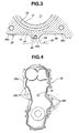
- Fig. 3 is a sectional view taken along the line "III-III" of Fig. 1; and
- Fig. 4 is a back view a front cover that is to be fixed to a front wall of the cylinder block.
- Preferring to the drawings, particularly Figs. 1 and 2, there is shown a
cylinder block 10 of an internal combustion engine, according to the present teaching. The engine to whichcylinder block 10 is practically applied is of an in-line four cylinder water cooled type. In use, the engine is transversely mounted in an engine room of a vehicle body with its intake side facing forward and its exhaust side facing backward. -
Cylinder block 10 is constructed of a die-cast aluminum allow or the like. - As is seen from Figs. 2 and 3,
cylinder block 10 is of a so-called open deck type having awater jacket 18 defined therein, of which upper end is largely exposed to anupper deck portion 20 ofcylinder block 10. - As is understood from Figs. 2 and 3, in
cylinder block 10, there are formed four cylinders (or cylinder bores) 11 which are aligned. Although not shown, a piston is operatively disposed in each ofcylinders 11. - Each
cylinder 11 is defined by acylindrical cylinder wall 12. - As is understood from Fig. 2, a generally upper half of each
cylinder wall 12 is surrounded by a cylindricaljacket side wall 14 leavingtherebetween water jacket 18. As is known, heat ofcylinder walls 12 produced as a result of combustion of air/fuel mixture in combustion chambers ofcylinders 11 is absorbed by cooling water that is forced to flow inwater jacket 18. - In order to reduce an axial length of
cylinder block 10, a so-called siamesed arrangement is employed wherein mutually adjacent parts of neighboringcylinder walls 12 are merged to with another. - As is seen from Fig. 2, each
cylinder wall 12 extends vertically between the above-mentionedupper deck portion 20 and alower deck portion 22. - As is seen from Figs. 1 and 2, from
lower deck portion 22, there extends downward acrank case 24. As is known,crank case 24 comprises a plurality of bearingcap mounting walls 26 that rotatably support a crankshaft with the aid of bearing caps (not shown). - As is understood from Fig. 2, on
upper deck portion 20, there is tightly mounted a cylinder head (not shown) with a cylinder head gasket hermetically put therebetween. For this tight mounting, a plurality of head bolts (not shown) are used. - A
jacket bottom wall 16 defining therein a bottom surface ofwater jacket 18 extends between a lower end of eachjacket side wall 14 and a middle portion of thecorresponding cylinder wall 12. With this,jacket bottom wall 16 is positioned abovelower deck portion 22, so thatwater jacket 18 is formed about only an upper part of eachcylinder wall 12. That is, the shallowbottom water jacket 18 is provided. - Due to this construction of
water jacket 18, the upper portion ofcylinder wall 12 near a combustion chamber is effectively cooled by cooling water, and due to absence of water jacket around the lower part ofcylinder wall 12, weight reduction ofcylinder block 10 is possible. Of course, other advantages such as suppression of over cooling, improvement in fuel consumption, improvement in exhaust characteristics, improvement in heating characteristics of heating system, etc., are also obtainable. - As is seen from Figs. 1 and 2, to a
front wall 28 ofcylinder block 10 to which a front cover 38 (see Fig. 4) is to be fixed, there are exposed a front part ofupper deck portion 20, a front part oflower deck portion 22, a front one ofcylinder walls 12, a front one ofjacket side walls 14 and a front one ofjacket bottom walls 16. That is,front wall 28 is substantially constructed by the front part ofupper deck portion 20, the front part oflower deck portion 22, the front one ofcylinder walls 12, the front one ofjacket side walls 14 and the front one ofjacket bottom walls 16. - It is to be noted that when the corresponding engine is transversely installed in the engine room,
front wall 28 ofcylinder block 10 faces leftward with respect to the vehicle. - As is seen from Figs. 1 and 2, to
front wall 28 ofcylinder block 10, there are also exposed anupper deck flange 30 that extends alongupper deck portion 20, alower deck flange 32 that extends alonglower deck portion 22, a cover mountingleft flange 34a that extends along a left periphery ofcylinder block 10, a cover mountingright flange 34b that extends along a right periphery ofcylinder block 10, and left and righthead bolt bosses - Cover mounting left and
right flanges bolt openings 35 for connecting a peripheral portion offront cover 38 thereto by means of connecting bolts (not shown). - As is seen from Fig. 2,
lower deck flange 32 is formed with awater passage 33 that is communicated with the above-mentionedwater jacket 18. Due to provision ofsuch water passage 33,lower deck flange 32 is expanded to have a rounded outer surface, as shown. If desired,such water passage 33 may be removed fromlower deck flange 32. - Front cover 38 (see Fig. 4) is constructed of a die-cast aluminum allow or the like. As shown,
front cover 38 is formed with a plurality ofbolt openings 38b at itsperipheral flange portion 38a. That is, the above-mentioned connecting bolts pass throughbolt openings 38b for securingfront cover 38 tofront wall 28 ofcylinder block 10. - As is best seen from Fig. 1,
front wall 28 ofcylinder block 10 is integrally formed with a reinforcing structure for reinforcing an entire construction ofcylinder block 10. - The reinforcing structure comprises a
vertical rib 42 and alateral rib 44 which are arranged to cross at generally right angles. - As shown,
vertical rib 42 is arranged at an upper half area offront wall 28 and extends vertically along an imaginary plane "L1" on which the axes of the fourcylinders 11 lie. -
Vertical rib 42 has an upper end merged with a front edge ofupper deck flange 30 and a lower end merged with a front edge oflower deck flange 32. That is,vertical rib 42 extends vertically between the front edge ofupper deck flange 30 and that oflower deck flange 32. - As is understood from Figs. 1 and 2,
lateral rib 44 is arranged at the upper half area offront wall 28 and extends laterally along the front one ofjacket bottom walls 16. That is,lateral rib 44 constitutes a raised ridge of the front one ofjacket bottom walls 16. - As is seen from Fig. 1,
lateral rib 44 has a left end merged with lefthead bolt boss 36a and a right end merged with right head bolt boss 37b. - As is seen from Fig. 2, at the area of
front wall 28,jacket side wall 14 projects beyondcylinder wall 12, andvertical rib 42 has a common top ridge throughout the length thereof. Thus, anupper part 42A ofvertical rib 42 that is arranged onjacket side wall 14 has a smaller projection degree fromjacket wall 14 and alower part 42B ofvertical rib 42 that is arranged on the lower portion ofcylinder wall 12 has a larger projection degree fromcylinder wall 12. - As is best seen from Fig. 1, at the portion of
front wall 28 wherevertical rib 42 andlateral rib 44 cross, there is integrally formed abolt boss 46 that has a threadedbolt opening 46a. - As is understood from Figs. 1, 3 and 4, when
front cover 38 is fixed tofront wall 28 ofcylinder block 10, a center bolt (not shown) passing through a center bolt boss opening 39 offront cover 38 is engaged with threaded bolt opening 46a ofbolt boss 46 offront wall 28. Preferably,bolt boss 46 is cylindrical in shape and has a larger size and thickness. - In the following, various advantages provided by the present teaching will be described.
- According to the teaching, reinforcing structure is provided by
front wall 28 ofcylinder block 10. That is, due to provision ofvertical rib 42 andlateral rib 44 which cross at generally right angles, the rigidity offront wall 28 and thus that ofcylinder block 10 is remarkably increased. Thus, undesired deformation ofcylinder wall 12 and that offront wall 28 are assuredly suppressed. - Since
lateral rib 44 is constructed to constitute the ridge of the front one of jacketbottom walls 16,jacket bottom wall 16 where a stress is concentrated under operation of the engine can have a satisfied rigidity. Thus, undesired deformation of jacketbottom wall 16 and thus that ofcylinder wall 12 are suppressed. - According to the teaching, the upper end of
vertical rib 42 is merged withupper deck flange 30, which increases the rigidity ofupper deck flange 30. Thus, undesired deformation ofupper deck flange 30, which would be caused by a strong resiliency of a cylinder head gasket hermetically put betweencylinder head 10 and a cylinder head (not shown), is assuredly suppressed. - According to the teaching, the center portion of
front cover 38 is tightly bolted to boltboss 46 offront wall 28 ofcylinder block 10 in addition to the bolting of the peripheral portion thereof tofront wall 28 ofcylinder block 10. Accordingly, undesired vibration offront cover 38 is assuredly suppressed. -
Bolt boss 46 is provided by making good use of the crossing part betweenvertical rib 42 andlateral rib 44. This brings about a simpler construction ofcylinder block 10 as compared with a conventional case wherein such bolt boss (46) is independently raised fromfront wall 28. - According to the teaching,
vertical rib 42 extends betweenupper deck flange 30 andlower deck flange 32 andlateral rib 44 extends between lefthead bolt boss 36a and righthead bolt boss 36b. Thus, a so-called grid shaped reinforcing structure is provided byfront wall 28 ofcylinder block 10, which assuredly providesfront wall 28 with a satisfied rigidity against the stress concentration. - Although the foregoing description is directed to the in-line four cylinder water cooler type internal combustion engine, the present teaching is applicable to other type internal combustion engines such as in-line three cylinder engine, in-line five cylinder engine, in-line six cylinder engine, in-line seven cylinder engine, in-line eight cylinder engine and the like.
Claims (9)
- A cylinder block of an internal combustion engine, comprising:an upper deck portion (20) on which a cylinder head is to be mounted;a lower deck portion (22) from which a crank case (24) extends downward;aligned cylinder walls (12) each extending vertically between the upper and lower deck portions (20, 22), the cylinder walls (12) having cylinder bores (11) defined therein respectively;jacket side walls (14) respectively surrounding the cylinder walls (12) so that a water jacket (18) is defined between each jacket side wall (14) and the corresponding cylinder wall (12);jacket bottom walls (16) each extending between a vertically lowermost end of each jacket side wall (14) and a vertically middle part of the corresponding cylinder wall (12), the jacket bottom walls (16) being positioned above the lower deck portion (22); a front wall (28) that constitutes an axial end wall of the cylinder block (10), the front wall (28) being integral with a front part of the upper deck portion (20), a front part of the lower deck portion (22), a front one of the cylinder walls (12), a front one of the jacket side walls (14) and a front one of the jacket bottom walls (16);characterized bya reinforcing structure integrally formed on the front wall (28) for reinforcing an entire construction of the cylinder block (10), the reinforcing structure being of a type that is raised from a major surface of the front wall, wherein the reinforcing structure comprises mutually crossing vertical and lateral ribs (42, 44), the vertical rib (42) extending between the upper deck portion (20) and the lower deck portion (22), and the lateral rib (44) forming a raised ridge of the front one of the jacket bottom walls (16).
- A cylinder block according to claim 1, characterized in that the reinforcing structure further comprises two head bolt bosses (36a, 36b) that are integrally formed on the front wall (28), each head bolt boss (36a, 36b) being constructed to catch a head bolt used for securing the cylinder head to the upper deck portion (20).
- A cylinder block according to claim 2, characterized in that the head bolt bosses (36a, 36b) have respective lower ends between which the lateral rib (44) extends.
- A cylinder block according to at least one of the claim 1 to 3, characterized in that the vertical and lateral ribs (42, 44) have at their crossing portion a bolt boss (46) that is constructed to catch a connecting bolt used for securing a middle portion of a front cover (38) to the front wall (28).
- A cylinder block according to claim 4, characterized in that the front wall (28) is formed at its peripheral portion with a plurality of bolt openings (35) that are constructed to catch connecting bolts used for securing a peripheral portion of the front cover (38) to the front wall (28).
- A cylinder block according to at least one of the claims 1 to 5, characterized in that the vertical rib (42) extends vertically along an imaginary plane "L1" on which axes of the cylinder bores (11) lie.
- A cylinder block according to at least one of the claims 1 to 6, characterized in that the reinforcing structure comprises a raised bolt boss (46) that is integrally formed on the front one of the jacket bottom walls (16) to catch a connecting bolt used for securing a middle portion of a front cover (38) to the front wall (28).
- A cylinder block according to claim 7, characterized in that the raised bolt boss (46) is positioned on an imaginary plane on which respective axes of the cylinder bores (11) lie.
- A cylinder block according to claim 8, characterized in that the raised bolt boss (46) is arranged to connect a generally middle portion of a front cover (38) thereto by means of a connecting bolt.
Applications Claiming Priority (2)
| Application Number | Priority Date | Filing Date | Title |
|---|---|---|---|
| JP2003351586 | 2003-10-10 | ||
| JP2003351586A JP4196803B2 (en) | 2003-10-10 | 2003-10-10 | Internal combustion engine cylinder block |
Publications (2)
| Publication Number | Publication Date |
|---|---|
| EP1522704A1 EP1522704A1 (en) | 2005-04-13 |
| EP1522704B1 true EP1522704B1 (en) | 2007-07-04 |
Family
ID=34309273
Family Applications (1)
| Application Number | Title | Priority Date | Filing Date |
|---|---|---|---|
| EP04023252A Expired - Lifetime EP1522704B1 (en) | 2003-10-10 | 2004-09-29 | Cylinder block of internal combustion engine |
Country Status (5)
| Country | Link |
|---|---|
| US (1) | US7077079B2 (en) |
| EP (1) | EP1522704B1 (en) |
| JP (1) | JP4196803B2 (en) |
| CN (1) | CN100591908C (en) |
| DE (1) | DE602004007339T2 (en) |
Families Citing this family (4)
| Publication number | Priority date | Publication date | Assignee | Title |
|---|---|---|---|---|
| PL1699512T3 (en) | 2003-11-03 | 2012-11-30 | Glaxo Group Ltd | A fluid dispensing device |
| JP4187045B2 (en) * | 2007-03-16 | 2008-11-26 | トヨタ自動車株式会社 | Cylinder block |
| CN101956622B (en) * | 2010-10-31 | 2012-05-23 | 无锡开普动力有限公司 | Water-cooled straight engine body |
| EP3088719B1 (en) * | 2013-12-27 | 2020-02-05 | Aichi Machine Industry Co., Ltd. | Cylinder block and internal combustion engine |
Family Cites Families (10)
| Publication number | Priority date | Publication date | Assignee | Title |
|---|---|---|---|---|
| JPS5816334U (en) * | 1973-06-21 | 1983-02-01 | ナシヨナル リサ−チ デベロツプメント コ−ポレ−シヨン | internal combustion engine |
| US4237847A (en) * | 1979-03-21 | 1980-12-09 | Cummins Engine Company, Inc. | Composite engine block having high strength to weight ratio |
| JPS6313407Y2 (en) * | 1980-10-31 | 1988-04-15 | ||
| JPS5874851A (en) * | 1981-10-28 | 1983-05-06 | Toyota Motor Corp | Cylinder block made of aluminum alloy |
| IT1182082B (en) * | 1984-12-13 | 1987-09-30 | Honda Motor Co Ltd | CYLINDER LOCK STRUCTURE FOR MULTI-CYLINDER INTERNAL COMBUSTION ENGINE |
| JPH0579195U (en) * | 1992-03-31 | 1993-10-26 | マツダ株式会社 | Belt cover mounting structure for V-type engine |
| US5253615A (en) * | 1992-12-24 | 1993-10-19 | Ford Motor Company | Cylinder block cylinder bore isolator |
| JP3079835B2 (en) * | 1993-04-16 | 2000-08-21 | スズキ株式会社 | Cylinder block structure |
| JP3644299B2 (en) * | 1999-04-02 | 2005-04-27 | 日産自動車株式会社 | Cylinder block for water-cooled internal combustion engine |
| JP3843724B2 (en) * | 2000-10-03 | 2006-11-08 | マツダ株式会社 | Engine cylinder block structure |
-
2003
- 2003-10-10 JP JP2003351586A patent/JP4196803B2/en not_active Expired - Lifetime
-
2004
- 2004-09-29 DE DE602004007339T patent/DE602004007339T2/en not_active Expired - Lifetime
- 2004-09-29 EP EP04023252A patent/EP1522704B1/en not_active Expired - Lifetime
- 2004-10-07 US US10/959,577 patent/US7077079B2/en not_active Expired - Lifetime
- 2004-10-10 CN CN200410084939A patent/CN100591908C/en not_active Expired - Lifetime
Also Published As
| Publication number | Publication date |
|---|---|
| DE602004007339D1 (en) | 2007-08-16 |
| CN100591908C (en) | 2010-02-24 |
| CN1605736A (en) | 2005-04-13 |
| US20050076861A1 (en) | 2005-04-14 |
| US7077079B2 (en) | 2006-07-18 |
| JP4196803B2 (en) | 2008-12-17 |
| EP1522704A1 (en) | 2005-04-13 |
| JP2005113855A (en) | 2005-04-28 |
| DE602004007339T2 (en) | 2007-10-31 |
Similar Documents
| Publication | Publication Date | Title |
|---|---|---|
| US8474442B2 (en) | Structural oil baffle for engine covers | |
| US5611301A (en) | Structural enclosure of combustion engines for the purpose of reducing engine noise | |
| JP3967552B2 (en) | Gas-liquid separator for engines | |
| CN106894906B (en) | The cooling structure of multicylinder engine | |
| JP4258339B2 (en) | Internal combustion engine cylinder block | |
| CA1057148A (en) | Cylinder head mounting apparatus for internal combustion engines | |
| JPH07197865A (en) | Intake device for V-type multi-cylinder engine | |
| EP1522704B1 (en) | Cylinder block of internal combustion engine | |
| US4643137A (en) | Engine construction | |
| KR100523307B1 (en) | Cylinder block for internal combustion engine | |
| US5873331A (en) | Cylinder head for a multi-cylinder internal combustion engine | |
| JP4262756B2 (en) | Multi-cylinder engine | |
| EP0208312A2 (en) | Cylinder head with coolant passage passing around outside of cylinder head fixing bolt boss and directing coolant flow toward squish area cooling passage portion | |
| US5743218A (en) | Liquid cooled cylinder head for an internal combustion engine | |
| US6338660B1 (en) | Exhaust system for an outboard motor | |
| JP6399074B2 (en) | Engine intake system with intercooler | |
| JP7332261B2 (en) | Body block of multi-cylinder internal combustion engine | |
| JP2003035229A (en) | V-type engine intake system | |
| US7036479B2 (en) | Cylinder block for engine | |
| JP7456713B2 (en) | Main block of multi-cylinder internal combustion engine | |
| JP3843954B2 (en) | Engine cylinder block structure | |
| JP2839826B2 (en) | Structure of Siamese type cylinder block | |
| JP3837313B2 (en) | engine | |
| JP3962269B2 (en) | Multi-cylinder engine | |
| JP2025082688A (en) | engine |
Legal Events
| Date | Code | Title | Description |
|---|---|---|---|
| PUAI | Public reference made under article 153(3) epc to a published international application that has entered the european phase |
Free format text: ORIGINAL CODE: 0009012 |
|
| 17P | Request for examination filed |
Effective date: 20040929 |
|
| AK | Designated contracting states |
Kind code of ref document: A1 Designated state(s): AT BE BG CH CY CZ DE DK EE ES FI FR GB GR HU IE IT LI LU MC NL PL PT RO SE SI SK TR |
|
| AX | Request for extension of the european patent |
Extension state: AL HR LT LV MK |
|
| AKX | Designation fees paid |
Designated state(s): DE FR GB |
|
| 17Q | First examination report despatched |
Effective date: 20051103 |
|
| GRAP | Despatch of communication of intention to grant a patent |
Free format text: ORIGINAL CODE: EPIDOSNIGR1 |
|
| GRAS | Grant fee paid |
Free format text: ORIGINAL CODE: EPIDOSNIGR3 |
|
| GRAA | (expected) grant |
Free format text: ORIGINAL CODE: 0009210 |
|
| AK | Designated contracting states |
Kind code of ref document: B1 Designated state(s): DE FR GB |
|
| REG | Reference to a national code |
Ref country code: GB Ref legal event code: FG4D |
|
| REF | Corresponds to: |
Ref document number: 602004007339 Country of ref document: DE Date of ref document: 20070816 Kind code of ref document: P |
|
| ET | Fr: translation filed | ||
| PLBE | No opposition filed within time limit |
Free format text: ORIGINAL CODE: 0009261 |
|
| STAA | Information on the status of an ep patent application or granted ep patent |
Free format text: STATUS: NO OPPOSITION FILED WITHIN TIME LIMIT |
|
| 26N | No opposition filed |
Effective date: 20080407 |
|
| REG | Reference to a national code |
Ref country code: FR Ref legal event code: PLFP Year of fee payment: 13 |
|
| REG | Reference to a national code |
Ref country code: FR Ref legal event code: PLFP Year of fee payment: 14 |
|
| REG | Reference to a national code |
Ref country code: FR Ref legal event code: PLFP Year of fee payment: 15 |
|
| PGFP | Annual fee paid to national office [announced via postgrant information from national office to epo] |
Ref country code: GB Payment date: 20230823 Year of fee payment: 20 |
|
| PGFP | Annual fee paid to national office [announced via postgrant information from national office to epo] |
Ref country code: FR Payment date: 20230822 Year of fee payment: 20 Ref country code: DE Payment date: 20230822 Year of fee payment: 20 |
|
| REG | Reference to a national code |
Ref country code: DE Ref legal event code: R071 Ref document number: 602004007339 Country of ref document: DE |
|
| PG25 | Lapsed in a contracting state [announced via postgrant information from national office to epo] |
Ref country code: GB Free format text: LAPSE BECAUSE OF EXPIRATION OF PROTECTION Effective date: 20240928 |
|
| REG | Reference to a national code |
Ref country code: GB Ref legal event code: PE20 Expiry date: 20240928 |
|
| PG25 | Lapsed in a contracting state [announced via postgrant information from national office to epo] |
Ref country code: GB Free format text: LAPSE BECAUSE OF EXPIRATION OF PROTECTION Effective date: 20240928 |