EP1522394A2 - Kreissäge mit einem verstellbaren Spaltkeil - Google Patents
Kreissäge mit einem verstellbaren Spaltkeil Download PDFInfo
- Publication number
- EP1522394A2 EP1522394A2 EP04009771A EP04009771A EP1522394A2 EP 1522394 A2 EP1522394 A2 EP 1522394A2 EP 04009771 A EP04009771 A EP 04009771A EP 04009771 A EP04009771 A EP 04009771A EP 1522394 A2 EP1522394 A2 EP 1522394A2
- Authority
- EP
- European Patent Office
- Prior art keywords
- adjusting
- circular saw
- splitting wedge
- adjustment
- spacer
- Prior art date
- Legal status (The legal status is an assumption and is not a legal conclusion. Google has not performed a legal analysis and makes no representation as to the accuracy of the status listed.)
- Granted
Links
Images


Classifications
-
- B—PERFORMING OPERATIONS; TRANSPORTING
- B27—WORKING OR PRESERVING WOOD OR SIMILAR MATERIAL; NAILING OR STAPLING MACHINES IN GENERAL
- B27G—ACCESSORY MACHINES OR APPARATUS FOR WORKING WOOD OR SIMILAR MATERIALS; TOOLS FOR WORKING WOOD OR SIMILAR MATERIALS; SAFETY DEVICES FOR WOOD WORKING MACHINES OR TOOLS
- B27G19/00—Safety guards or devices specially adapted for wood saws; Auxiliary devices facilitating proper operation of wood saws
- B27G19/08—Accessories for keeping open the saw kerf, e.g. riving knives or wedge plates
Definitions
- the present invention relates to a circular saw with an adjustable Splitting wedge according to the preamble of claim 1.
- DE 83 12 668 U is a circular saw with an adjustable riving knife known.
- the alignment of the splitting wedge in the plane of the saw blade is done by a set screw, by means of which the splitting wedge can be bent.
- the riving knife is firmly connected to a lower end with a housing.
- the adjusting screw is arranged above the fixed connection, so that the Upper part of the splitting wedge by adjusting the adjusting screw in the plane of the Saw blade can be pressed.
- a disadvantage of this arrangement is that the splitting wedge of a constant bending load is exposed. Furthermore, the riving knife must be so thin that the Bending by the set screw is easily possible. This leads to a total unstable construction. A bending of the splitting wedge during the sawing process is also possible through the workpiece and causes an imprecise Cut.
- Another possibility is to split the riving knife on a high-precision To attach mounting part, so that an adjustment of the riving knife no longer necessary is.
- the disadvantage of this is high production costs for the support part and a lack of customization of saw blades different Thickness.
- the present invention is based on the problem, the splitting wedge on a Circular saw to construct so that it is stable and at the same time a Adjustment in the plane of the saw blade with ease of use allows becomes.
- a basic idea of the present invention is that the splitting wedge must not be bent in the plane of the saw blade, but firmly a spacer is mounted and parallel through this in the plane of the saw blade is adjusted.
- splitting wedge in addition to the parallel adjustment also in its position relative to the saw blade is adjustable.
- the spacer has two adjustment components, the relative to each other at inclined planes along are displaceable.
- the inclined planes on the adjusting components be formed by several pips. There should be such an angle be predeterminable that with a slight displacement of the two inclined planes against each other already a recognizable parallel offset of the splitting wedge is present. For this purpose, several teeth are not mandatory. Using several points is the bearing surface between the adjusting components but larger, without the adjustment itself made thicker Need to become.
- adjustment components are centered by a combination of a write and a nut including a diaphragm spring are held together and the splitting wedge is fastened at the same time by means of this combination can be dispensed with an additional fastener for the riving knife.
- the two adjusting components are pressed against each other by the disc spring, as long as no additional force acts.
- the additional force is advantageously applied by a set screw, one of the adjusting components relative to the other adjusting component shifts.
- the spacer has no two adjustment components but instead a steering linkage.
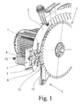
- the circular saw shown in Fig. 1 has a support structure 1, a saw blade 2, a splitting wedge 3 and a spacer 4.
- the saw blade 2 is rotatable attached to the support structure 1 and is driven by a motor.
- the spacer 4 is attached to the support structure 1.
- the splitting wedge 3 is by means of a fastener 5, on the spacer 4 in a holding position attached and by the spacer 4 parallel to itself in the plane of the saw blade 2 adjustable.
- the fastening element 5 has, preferably, a combination of a screw and a nut on.
- the riving knife 3 has an arcuate slot 7 here.
- the fastener 5, with which the splitting wedge 3 is fastened to the spacer 4 extends through the slot 7.
- Through the slot 7 is a change the holding position of the riving knife 3 allows.
- the change of the holding position then allows a height and / or distance adjustment of the splitting wedge. 3 relative to the saw blade 2.
- the spacer 4 has two protruding tabs 8, 9 (FIG. 1), preferably on the top and bottom on. When attached to the spacer 4 Splitting wedge 3 protrude the two tabs 8, 9 in the arcuate slot 7 of Splitting wedge 3 into it. From the tabs 8, 9 opposite side is a fixing plate 10, the recesses 11, 12 for the tabs 8, 9th has pressed against the riving knife 3. The fastening element 5, the Splitting wedge 3 attached to the spacer 4, fixed beyond the also Fastening washer 10 to riving knife 3 and spacer 4.
- the spacer 4 has a first and a second adjusting member 13, 14 and an adjusting mechanism 15.
- the first Adjustment member 13 is attached to the support structure 1.
- the splitting wedge 3 is attached to the second adjustment member 14.
- the adjusting components 13, 14 each have an inclined plane 16, 17.
- the adjusting components 13,14 are with the inclined planes 16, 17 arranged against each other. A shift the inclined planes 16, 17 against each other thus causes a parallel adjustment of the splitting wedge 3.
- the inclined planes 16, 17 respectively several spikes 18, 19, 20 on.
- such an angle can be specified, that at a small displacement of the two inclined planes 16, 17 against each other already a recognizable parallel offset of the splitting wedge 3 is present.
- the teeth 18, 19, 20 ensures that the support surface between the adjusting components 13, 14 remains large, without requiring the adjustment components 13, 14 must be thicker. The large contact surface leads to a more stable guidance of the splitting wedge 3.
- Both adjusting components 13, 14 each have a recess 21 in the middle, 22 on (Fig. 2, 3). They are by means of a fastener 5a, which through the recesses 21, 22 extends, fastened against each other.
- the fastener 5a is the same as the fastener 5, with which the splitting wedge 3 on the spacer 4 or more precisely is attached to the second adjustment member 14 of the spacer 4.
- a plate spring 23 is provided which generates a restoring force.
- the restoring force By the restoring force, the two adjustment components 13, 14 against each other pressed, as long as no counterforce acts.
- the restoring force it can also by another construction, in particular another Spring arrangement, be provided.
- the counterforce for the adjustment of the Splitting wedge 3 is applied by the adjusting mechanism 15.
- the first adjustment member 13 is, preferably, attached to the support structure and the second adjustment member 14 with the riving knife 3 is through the Adjusting mechanism 15 relative to the first adjustment member 13 adjustable.
- the adjusting mechanism 15 has a projection 24 on the second adjusting component 14, an adjusting screw 25 and a stop 26.
- the supernatant 24 protrudes into an edge-side recess 27 of the first adjustment member 13th into it.
- the projection 24 has an internal thread parallel to the plane of the Saw blade 2 runs on.
- the screw 25th screwed is the screw 25th screwed.
- the screw 25 is preferably designed as Allen screw.
- composite arrangement lies the screw 25 to the stop 26 at.
- the stop 26 is replaced by a Surface formed on the first adjustment member 13.
- the internal thread is preferably by an inserted into the supernatant 24 hex nut realized.
- the adjusting components 13, 14 are preferably unprocessed cast aluminum parts. This allows a cost-effective production.
- the handlebars 30, 31 are connected by one or two connecting rods 32, 33rd connected with each other.
- the handlebars 30, 31 together with the Connecting rods 32, 33 a parallelogram.
- the adjustment mechanism 15th is attached to the second handlebar 31.
- the adjustment mechanism 15th has an adjusting screw 25, preferably an Allen screw, and an internal thread 28 perpendicular to the plane of the saw blade 2.
- the adjusting screw 25 is screwed into the internal thread 28.
- the set screw 25 is located on a stop 26 on the first handlebar 31st at. By turning the screw 25 in a clockwise direction, the handlebars 30, 31 shifted parallel to each other.
- a restoring force is required, which is the shift the two handlebars 30, 31 realized relative to each other.
- the Restoring force is, preferably, by a tension spring 34, which between the two handlebars 30, 31 is arranged, provided.
Landscapes
- Life Sciences & Earth Sciences (AREA)
- Engineering & Computer Science (AREA)
- Mechanical Engineering (AREA)
- Wood Science & Technology (AREA)
- Forests & Forestry (AREA)
- Details Of Cutting Devices (AREA)
- Sawing (AREA)
- Stringed Musical Instruments (AREA)
- Harvester Elements (AREA)
- Soil Working Implements (AREA)
- Knives (AREA)
Abstract
Description
- Fig. 1
- eine perspektivische, ausschnittweise Ansicht einer Kreissäge mit einem Distanzstück zur Spaltkeilverstellung,
- Fig. 2
- eine perspektivische Ansicht eines Verstellbauteils,
- Fig. 3
- eine perspektivische Ansicht eines Distanzstücks,
- Fig. 4
- eine perspektivische Ansicht eines weiteren Ausführungsbeispiels.
Claims (9)
- Kreissäge mit einem an einer Tragkonstruktion (1) drehbar gelagerten Sägeblatt (2) und einem relativ zu dem Sägeblatt (2) verstellbaren Spaltkeil (3),
dadurch gekennzeichnet, daß der Spaltkeil (3) an einem Distanzstück (4) befestigt und mittels des Distanzstückes (4) relativ zu der Tragkonstruktion (1) parallel zu sich selbst in die Ebene des Sägeblatts (2) verstellbar ist. - Kreissäge nach Anspruch 1, dadurch gekennzeichnet, daß der Spaltkeil (3) mittels eines Befestigungselements (5) an dem Distanzstück (4) in einer Haltestellung befestigt ist,
wobei, vorzugsweise, das Befestigungselement (5) eine Kombination aus einer Schraube und einer Mutter aufweist. - Kreissäge nach Anspruch 2 dadurch gekennzeichnet, daß der Spaltkeil (3) einen, vorzugsweise bogenförmigen Schlitz (7) aufweist, durch den das Befestigungselement (5) verläuft, so daß durch Änderung der Haltestellung eine Höhen- und/oder Distanzverstellung des Spaltkeils (3) relativ zum Sägeblatt (2) möglich ist,
wobei, vorzugsweise, das Distanzstück (4) zwei Laschen (8, 9) aufweist, die Laschen (8, 9) in zusammengesetztem Zustand in den Schlitz (7) des Spaltkeils (3) hineinragen und eine Befestigungsscheibe (10) mit Aussparungen (11, 12) für die Laschen (8, 9) in zusammengesetztem Zustand von der den Laschen (8, 9) gegenüberliegenden Seite gegen den Spaltkeil (3) drückend angeordnet ist. - Kreissäge nach einem der Ansprüche 1 bis 3, dadurch gekennzeichnet, daß das Distanzstück (4) ein erstes und ein zweites Verstellbauteil (13, 14) und einen Verstellmechanismus (15) aufweist, daß die Verstellbauteile (13, 14) schiefe Ebenen (16, 17) aufweisen, daß die Verstellbauteile (13, 14) mit den schiefen Ebenen (16, 17) gegeneinander angeordnet und gegeneinander verschiebbar sind und daß die Parallelverstellung des Spaltkeils (3) durch die Verschiebung der schiefen Ebenen (16, 17) relativ zueinander erfolgt,
wobei, vorzugsweise, die schiefen Ebenen (16, 17) mehrere Zacken (18, 19, 20) aufweisen, wobei ein solcher Winkel vorgebbar ist, daß bei einer geringen Verschiebung der beiden schiefen Ebenen (16, 17) gegeneinander bereits ein erkennbarer paralleler Versatz des Spaltkeils (3) vorliegt. - Kreissäge nach Anspruch 4, dadurch gekennzeichnet, daß die Verstellbauteile (13, 14) mit den schiefen Ebenen (16, 17) gegeneinander angeordnet und verschiebbar sind und jeweils eine Aussparung (21, 22) aufweisen und daß die Verstellbauteile (13, 14) mittels eines Befestigungselements (5), welches durch die Aussparungen (21, 22) verläuft, zusammengehalten werden, und/oder
daß die Verstellbauteile (13, 14) mittels einer Rückstellkraft gegeneinander gedrückt sind, solange keine Gegenkraft wirkt, wobei, vorzugsweise, die Rückstellkraft mittels einer Tellerfeder (23) an dem Befestigungselement (5) erzeugt wird, und/oder
daß das erste Verstellbauteil (13) an der Tragkonstruktion (1) angebracht ist und das zweite Verstellbauteil (14) durch den Verstellmechanismus (15) relativ zu dem ersten Verstellbauteil (13) verstellbar ist, und/oder
daß der Verstellmechanismus (15) eine Stellschraube (25), vorzugsweise eine Inbusschraube, aufweist, die an einem Anschlag (26) des ersten Verstellbauteiles (13) anliegt und in ein Innengewinde in dem zweiten Verstellbauteil (14) geschraubt ist, wobei, vorzugsweise, das Innengewinde durch eine in das zweite Verstellbauteil (14) eingelegte Sechskantmutter realisiert ist, und/oder
daß die Verstellbauteile (13, 14) unbearbeitete Aluminiumgußteile sind. - Kreissäge nach einem der Ansprüche 1 bis 3, dadurch gekennzeichnet, daß das Distanzstück (4) ein erste und eine zweite Lenkstange (30, 31), mindestens eine Verbindungsstange (32, 33) und einen Verstellmechanismus (15) aufweist, daß die Lenkstangen (30, 31) mittels der Verbindungsstange(n) (32, 33) verbunden sind und daß die Parallelverstellung des Spaltkeils (3) durch eine Verstellung der Lenkstangen (30, 31) relativ zueinander erfolgt.
- Kreissäge nach Anspruch 6, dadurch gekennzeichnet, daß die erste Lenkstange (30) an der Tragkonstruktion (1) angebracht ist, und
daß der Spaltkeil (3) an der zweiten Lenkstange (31) mittels eines Befestigungselementes (5) befestigt ist, und/oder
daß der Verstellmechanismus (15) an einer der Lenkstangen (30, 31), vorzugsweise, an der zweiten Lenkstange (31), befestigt ist, und/oder
daß der Verstellmechanismus (15) eine Stellschraube (25), vorzugsweise eine Inbusschraube, aufweist, die an einem Anschlag (26) an der ersten Lenkstange (30) anliegt und in ein Innengewinde (28) in der zweiten Lenkstange (31) eingeschraubt ist, und/oder
daß die Lenkstangen (30, 31) mittels einer Rückstellkraft gegeneinander gedrückt sind, solange keine Gegenkraft wirkt, wobei, vorzugsweise, die Rückstellkraft mittels einer Zugfeder (34) zwischen den Lenkstangen (30, 31) erzeugt wird, wobei, vorzugsweise, die Zugfeder (34) zwischen den Lenkstangen (30, 31) um die Stellschraube (25) herum, angeordnet ist, und/oder
daß sich die Lenkstangen (30, 31) bei größtmöglichem Versatz des Spaltkeils (3) parallel gegenüberstehen. - Kreissäge nach einem der Ansprüche 1 bis 7, dadurch gekennzeichnet, daß die Kreissäge eine Tischkreissäge ist.
- Kreissäge nach einem der Ansprüche 1 bis 7, dadurch gekennzeichnet, daß die Kreissäge eine Handkreissäge ist.
Applications Claiming Priority (2)
| Application Number | Priority Date | Filing Date | Title |
|---|---|---|---|
| DE10347915 | 2003-10-10 | ||
| DE10347915A DE10347915B3 (de) | 2003-10-10 | 2003-10-10 | Kreissäge mit einem verstellbaren Spaltkeil |
Publications (3)
| Publication Number | Publication Date |
|---|---|
| EP1522394A2 true EP1522394A2 (de) | 2005-04-13 |
| EP1522394A3 EP1522394A3 (de) | 2007-01-10 |
| EP1522394B1 EP1522394B1 (de) | 2008-07-30 |
Family
ID=33483137
Family Applications (1)
| Application Number | Title | Priority Date | Filing Date |
|---|---|---|---|
| EP04009771A Expired - Lifetime EP1522394B1 (de) | 2003-10-10 | 2004-04-24 | Kreissäge mit einem verstellbaren Spaltkeil |
Country Status (3)
| Country | Link |
|---|---|
| EP (1) | EP1522394B1 (de) |
| AT (1) | ATE402796T1 (de) |
| DE (2) | DE10347915B3 (de) |
Cited By (1)
| Publication number | Priority date | Publication date | Assignee | Title |
|---|---|---|---|---|
| CN101450399B (zh) * | 2007-12-06 | 2010-08-25 | 张理政 | 具有保护结构的锯切装置 |
Families Citing this family (4)
| Publication number | Priority date | Publication date | Assignee | Title |
|---|---|---|---|---|
| WO2016040447A1 (en) | 2014-09-09 | 2016-03-17 | Robert Bosch Gmbh | Table saw riving knife mounting arrangement |
| US12263615B2 (en) | 2020-11-23 | 2025-04-01 | Milwaukee Electric Tool Corporation | Circular saw |
| US12465982B2 (en) | 2022-02-24 | 2025-11-11 | Techtronic Cordless Gp | Track saw including plunge lockout mechanism |
| US12083613B2 (en) | 2022-10-18 | 2024-09-10 | Techtronic Cordless Gp | Track saw including plunge lockout mechanism |
Family Cites Families (3)
| Publication number | Priority date | Publication date | Assignee | Title |
|---|---|---|---|---|
| CH214230A (de) * | 1940-04-18 | 1941-04-15 | Mey Kg Maschf Mafell | Handkreissäge. |
| DE917746C (de) * | 1940-09-12 | 1954-09-09 | Leona Pflaumer Geb Steuer | Vorrichtung zum Halten des Spaltkeiles einer Kreissaege |
| GB2273078A (en) * | 1992-12-04 | 1994-06-08 | Black & Decker Inc | Adjustable riving knife |
-
2003
- 2003-10-10 DE DE10347915A patent/DE10347915B3/de not_active Expired - Fee Related
-
2004
- 2004-04-24 EP EP04009771A patent/EP1522394B1/de not_active Expired - Lifetime
- 2004-04-24 DE DE502004007718T patent/DE502004007718D1/de not_active Expired - Lifetime
- 2004-04-24 AT AT04009771T patent/ATE402796T1/de active
Cited By (1)
| Publication number | Priority date | Publication date | Assignee | Title |
|---|---|---|---|---|
| CN101450399B (zh) * | 2007-12-06 | 2010-08-25 | 张理政 | 具有保护结构的锯切装置 |
Also Published As
| Publication number | Publication date |
|---|---|
| DE10347915B3 (de) | 2004-12-23 |
| ATE402796T1 (de) | 2008-08-15 |
| EP1522394A3 (de) | 2007-01-10 |
| DE502004007718D1 (de) | 2008-09-11 |
| EP1522394B1 (de) | 2008-07-30 |
Similar Documents
| Publication | Publication Date | Title |
|---|---|---|
| DE4114187C2 (de) | ||
| DE19523348A1 (de) | Einstellmechanismus des Schrägstellungswinkels einer Verbund-Gehrungssäge | |
| DE19619820A1 (de) | Pedalkurbel mit verstellbarem Kurbelradius für Fahrradergometer | |
| DE68914276T2 (de) | Schnell einrastende zusatzeinheit für maschinen-schraubstöcke. | |
| EP2183072B1 (de) | Handwerkzeugmaschine | |
| EP0389604A1 (de) | Spanneinrichtung | |
| EP2412490A1 (de) | Befestigungsvorrichtung | |
| EP1955801A2 (de) | Gehrungssäge mit Winkelfixierungseinrichtung | |
| DE3209984A1 (de) | Schraubzwinge | |
| EP3272207A1 (de) | Arbeitsgerät mit über ein schwenkgelenk verbundenen teilgehäusen | |
| EP1663588B1 (de) | Grundplatte für ein elektrowerkzeug und verfahren zur herstellung derselben | |
| EP1522394B1 (de) | Kreissäge mit einem verstellbaren Spaltkeil | |
| EP1466689A1 (de) | Säbelsäge mit Führungsvorrichtung | |
| DE202008016711U1 (de) | Werkzeugmaschine, insbesondere Kapp- und Gehrungssäge | |
| DE4209668A1 (de) | Steuergerät, insbesondere zur Fernbedienung von hydraulischen Komponenten | |
| DE202021104502U1 (de) | Fixierwerkzeug, Fixierwerkzeugsatz sowie Zubehörsatz zur Benutzung zusammen mit einem tragbaren Bearbeitungsgerät | |
| DE102009036308B4 (de) | Sägeblattklemme | |
| DE20220893U1 (de) | Sägeblattbefestigungsvorrichtung für Stichsägen | |
| DE4233233C2 (de) | Handhebelpresse | |
| EP1916356A2 (de) | Fußplatte, Nivelliereinheit sowie Leitungskanal | |
| DE102005027818B4 (de) | Haltegriff mit universell verwendbarer Messerklinge | |
| DE10224127C1 (de) | Halter für ein Drehwerkzeug, insbesondere für einen Abstechstahl | |
| DE9306314U1 (de) | Vorrichtung zum Zertrennen von Gitterrosten | |
| EP4617022A1 (de) | Montageelement für eine führungsschiene sowie führungsanordnung zum führen einer handkreissäge | |
| DE233909C (de) |
Legal Events
| Date | Code | Title | Description |
|---|---|---|---|
| PUAI | Public reference made under article 153(3) epc to a published international application that has entered the european phase |
Free format text: ORIGINAL CODE: 0009012 |
|
| AK | Designated contracting states |
Kind code of ref document: A2 Designated state(s): AT BE BG CH CY CZ DE DK EE ES FI FR GB GR HU IE IT LI LU MC NL PL PT RO SE SI SK TR |
|
| AX | Request for extension of the european patent |
Extension state: AL HR LT LV MK |
|
| PUAL | Search report despatched |
Free format text: ORIGINAL CODE: 0009013 |
|
| AK | Designated contracting states |
Kind code of ref document: A3 Designated state(s): AT BE BG CH CY CZ DE DK EE ES FI FR GB GR HU IE IT LI LU MC NL PL PT RO SE SI SK TR |
|
| AX | Request for extension of the european patent |
Extension state: AL HR LT LV MK |
|
| 17P | Request for examination filed |
Effective date: 20070503 |
|
| AKX | Designation fees paid |
Designated state(s): AT BE BG CH CY CZ DE DK EE ES FI FR GB GR HU IE IT LI LU MC NL PL PT RO SE SI SK TR |
|
| GRAP | Despatch of communication of intention to grant a patent |
Free format text: ORIGINAL CODE: EPIDOSNIGR1 |
|
| GRAS | Grant fee paid |
Free format text: ORIGINAL CODE: EPIDOSNIGR3 |
|
| GRAA | (expected) grant |
Free format text: ORIGINAL CODE: 0009210 |
|
| AK | Designated contracting states |
Kind code of ref document: B1 Designated state(s): AT BE BG CH CY CZ DE DK EE ES FI FR GB GR HU IE IT LI LU MC NL PL PT RO SE SI SK TR |
|
| REG | Reference to a national code |
Ref country code: GB Ref legal event code: FG4D Free format text: NOT ENGLISH |
|
| REG | Reference to a national code |
Ref country code: CH Ref legal event code: EP |
|
| REF | Corresponds to: |
Ref document number: 502004007718 Country of ref document: DE Date of ref document: 20080911 Kind code of ref document: P |
|
| REG | Reference to a national code |
Ref country code: IE Ref legal event code: FG4D Free format text: LANGUAGE OF EP DOCUMENT: GERMAN |
|
| PG25 | Lapsed in a contracting state [announced via postgrant information from national office to epo] |
Ref country code: PT Free format text: LAPSE BECAUSE OF FAILURE TO SUBMIT A TRANSLATION OF THE DESCRIPTION OR TO PAY THE FEE WITHIN THE PRESCRIBED TIME-LIMIT Effective date: 20081230 Ref country code: ES Free format text: LAPSE BECAUSE OF FAILURE TO SUBMIT A TRANSLATION OF THE DESCRIPTION OR TO PAY THE FEE WITHIN THE PRESCRIBED TIME-LIMIT Effective date: 20081110 |
|
| PG25 | Lapsed in a contracting state [announced via postgrant information from national office to epo] |
Ref country code: SI Free format text: LAPSE BECAUSE OF FAILURE TO SUBMIT A TRANSLATION OF THE DESCRIPTION OR TO PAY THE FEE WITHIN THE PRESCRIBED TIME-LIMIT Effective date: 20080730 Ref country code: BG Free format text: LAPSE BECAUSE OF FAILURE TO SUBMIT A TRANSLATION OF THE DESCRIPTION OR TO PAY THE FEE WITHIN THE PRESCRIBED TIME-LIMIT Effective date: 20081030 Ref country code: FI Free format text: LAPSE BECAUSE OF FAILURE TO SUBMIT A TRANSLATION OF THE DESCRIPTION OR TO PAY THE FEE WITHIN THE PRESCRIBED TIME-LIMIT Effective date: 20080730 |
|
| REG | Reference to a national code |
Ref country code: IE Ref legal event code: FD4D |
|
| PG25 | Lapsed in a contracting state [announced via postgrant information from national office to epo] |
Ref country code: IE Free format text: LAPSE BECAUSE OF FAILURE TO SUBMIT A TRANSLATION OF THE DESCRIPTION OR TO PAY THE FEE WITHIN THE PRESCRIBED TIME-LIMIT Effective date: 20080730 Ref country code: DK Free format text: LAPSE BECAUSE OF FAILURE TO SUBMIT A TRANSLATION OF THE DESCRIPTION OR TO PAY THE FEE WITHIN THE PRESCRIBED TIME-LIMIT Effective date: 20080730 Ref country code: EE Free format text: LAPSE BECAUSE OF FAILURE TO SUBMIT A TRANSLATION OF THE DESCRIPTION OR TO PAY THE FEE WITHIN THE PRESCRIBED TIME-LIMIT Effective date: 20080730 |
|
| PG25 | Lapsed in a contracting state [announced via postgrant information from national office to epo] |
Ref country code: CZ Free format text: LAPSE BECAUSE OF FAILURE TO SUBMIT A TRANSLATION OF THE DESCRIPTION OR TO PAY THE FEE WITHIN THE PRESCRIBED TIME-LIMIT Effective date: 20080730 Ref country code: SK Free format text: LAPSE BECAUSE OF FAILURE TO SUBMIT A TRANSLATION OF THE DESCRIPTION OR TO PAY THE FEE WITHIN THE PRESCRIBED TIME-LIMIT Effective date: 20080730 Ref country code: RO Free format text: LAPSE BECAUSE OF FAILURE TO SUBMIT A TRANSLATION OF THE DESCRIPTION OR TO PAY THE FEE WITHIN THE PRESCRIBED TIME-LIMIT Effective date: 20080730 |
|
| PLBE | No opposition filed within time limit |
Free format text: ORIGINAL CODE: 0009261 |
|
| STAA | Information on the status of an ep patent application or granted ep patent |
Free format text: STATUS: NO OPPOSITION FILED WITHIN TIME LIMIT |
|
| 26N | No opposition filed |
Effective date: 20090506 |
|
| BERE | Be: lapsed |
Owner name: METABOWERKE G.M.B.H. Effective date: 20090430 |
|
| PG25 | Lapsed in a contracting state [announced via postgrant information from national office to epo] |
Ref country code: SE Free format text: LAPSE BECAUSE OF FAILURE TO SUBMIT A TRANSLATION OF THE DESCRIPTION OR TO PAY THE FEE WITHIN THE PRESCRIBED TIME-LIMIT Effective date: 20081030 |
|
| PG25 | Lapsed in a contracting state [announced via postgrant information from national office to epo] |
Ref country code: MC Free format text: LAPSE BECAUSE OF NON-PAYMENT OF DUE FEES Effective date: 20090430 |
|
| PG25 | Lapsed in a contracting state [announced via postgrant information from national office to epo] |
Ref country code: BE Free format text: LAPSE BECAUSE OF NON-PAYMENT OF DUE FEES Effective date: 20090430 Ref country code: PL Free format text: LAPSE BECAUSE OF FAILURE TO SUBMIT A TRANSLATION OF THE DESCRIPTION OR TO PAY THE FEE WITHIN THE PRESCRIBED TIME-LIMIT Effective date: 20080730 |
|
| PG25 | Lapsed in a contracting state [announced via postgrant information from national office to epo] |
Ref country code: GR Free format text: LAPSE BECAUSE OF FAILURE TO SUBMIT A TRANSLATION OF THE DESCRIPTION OR TO PAY THE FEE WITHIN THE PRESCRIBED TIME-LIMIT Effective date: 20081031 |
|
| PG25 | Lapsed in a contracting state [announced via postgrant information from national office to epo] |
Ref country code: LU Free format text: LAPSE BECAUSE OF NON-PAYMENT OF DUE FEES Effective date: 20090424 |
|
| PG25 | Lapsed in a contracting state [announced via postgrant information from national office to epo] |
Ref country code: HU Free format text: LAPSE BECAUSE OF FAILURE TO SUBMIT A TRANSLATION OF THE DESCRIPTION OR TO PAY THE FEE WITHIN THE PRESCRIBED TIME-LIMIT Effective date: 20090131 |
|
| PGFP | Annual fee paid to national office [announced via postgrant information from national office to epo] |
Ref country code: CH Payment date: 20110421 Year of fee payment: 8 |
|
| PG25 | Lapsed in a contracting state [announced via postgrant information from national office to epo] |
Ref country code: TR Free format text: LAPSE BECAUSE OF FAILURE TO SUBMIT A TRANSLATION OF THE DESCRIPTION OR TO PAY THE FEE WITHIN THE PRESCRIBED TIME-LIMIT Effective date: 20080730 |
|
| PGFP | Annual fee paid to national office [announced via postgrant information from national office to epo] |
Ref country code: AT Payment date: 20110418 Year of fee payment: 8 |
|
| PG25 | Lapsed in a contracting state [announced via postgrant information from national office to epo] |
Ref country code: CY Free format text: LAPSE BECAUSE OF FAILURE TO SUBMIT A TRANSLATION OF THE DESCRIPTION OR TO PAY THE FEE WITHIN THE PRESCRIBED TIME-LIMIT Effective date: 20080730 |
|
| PGFP | Annual fee paid to national office [announced via postgrant information from national office to epo] |
Ref country code: IT Payment date: 20110427 Year of fee payment: 8 |
|
| REG | Reference to a national code |
Ref country code: CH Ref legal event code: PL |
|
| REG | Reference to a national code |
Ref country code: AT Ref legal event code: MM01 Ref document number: 402796 Country of ref document: AT Kind code of ref document: T Effective date: 20120424 |
|
| PG25 | Lapsed in a contracting state [announced via postgrant information from national office to epo] |
Ref country code: LI Free format text: LAPSE BECAUSE OF NON-PAYMENT OF DUE FEES Effective date: 20120430 Ref country code: CH Free format text: LAPSE BECAUSE OF NON-PAYMENT OF DUE FEES Effective date: 20120430 Ref country code: AT Free format text: LAPSE BECAUSE OF NON-PAYMENT OF DUE FEES Effective date: 20120424 |
|
| PG25 | Lapsed in a contracting state [announced via postgrant information from national office to epo] |
Ref country code: IT Free format text: LAPSE BECAUSE OF NON-PAYMENT OF DUE FEES Effective date: 20120424 |
|
| REG | Reference to a national code |
Ref country code: FR Ref legal event code: PLFP Year of fee payment: 12 |
|
| PGFP | Annual fee paid to national office [announced via postgrant information from national office to epo] |
Ref country code: NL Payment date: 20150422 Year of fee payment: 12 |
|
| PGFP | Annual fee paid to national office [announced via postgrant information from national office to epo] |
Ref country code: GB Payment date: 20150423 Year of fee payment: 12 Ref country code: DE Payment date: 20150422 Year of fee payment: 12 |
|
| PGFP | Annual fee paid to national office [announced via postgrant information from national office to epo] |
Ref country code: FR Payment date: 20150422 Year of fee payment: 12 |
|
| REG | Reference to a national code |
Ref country code: DE Ref legal event code: R119 Ref document number: 502004007718 Country of ref document: DE |
|
| REG | Reference to a national code |
Ref country code: NL Ref legal event code: MM Effective date: 20160501 |
|
| GBPC | Gb: european patent ceased through non-payment of renewal fee |
Effective date: 20160424 |
|
| REG | Reference to a national code |
Ref country code: FR Ref legal event code: ST Effective date: 20161230 |
|
| PG25 | Lapsed in a contracting state [announced via postgrant information from national office to epo] |
Ref country code: DE Free format text: LAPSE BECAUSE OF NON-PAYMENT OF DUE FEES Effective date: 20161101 Ref country code: NL Free format text: LAPSE BECAUSE OF NON-PAYMENT OF DUE FEES Effective date: 20160501 Ref country code: GB Free format text: LAPSE BECAUSE OF NON-PAYMENT OF DUE FEES Effective date: 20160424 Ref country code: FR Free format text: LAPSE BECAUSE OF NON-PAYMENT OF DUE FEES Effective date: 20160502 |