EP1522074B1 - Vorrichtung und verfahren zur handhabung von platten - Google Patents
Vorrichtung und verfahren zur handhabung von platten Download PDFInfo
- Publication number
- EP1522074B1 EP1522074B1 EP03762638A EP03762638A EP1522074B1 EP 1522074 B1 EP1522074 B1 EP 1522074B1 EP 03762638 A EP03762638 A EP 03762638A EP 03762638 A EP03762638 A EP 03762638A EP 1522074 B1 EP1522074 B1 EP 1522074B1
- Authority
- EP
- European Patent Office
- Prior art keywords
- jaws
- another
- objects
- aperture
- away
- Prior art date
- Legal status (The legal status is an assumption and is not a legal conclusion. Google has not performed a legal analysis and makes no representation as to the accuracy of the status listed.)
- Expired - Lifetime
Links
- 238000000034 method Methods 0.000 title claims abstract description 13
- 238000007373 indentation Methods 0.000 claims description 14
- 238000006073 displacement reaction Methods 0.000 claims description 8
- 238000004519 manufacturing process Methods 0.000 description 7
- 230000000694 effects Effects 0.000 description 3
- 230000032258 transport Effects 0.000 description 3
- 230000005484 gravity Effects 0.000 description 2
- 239000000463 material Substances 0.000 description 2
- 239000011248 coating agent Substances 0.000 description 1
- 238000000576 coating method Methods 0.000 description 1
- 230000000295 complement effect Effects 0.000 description 1
- 239000002131 composite material Substances 0.000 description 1
- 230000001419 dependent effect Effects 0.000 description 1
- 238000005516 engineering process Methods 0.000 description 1
- 239000010410 layer Substances 0.000 description 1
- 239000002184 metal Substances 0.000 description 1
- 239000000203 mixture Substances 0.000 description 1
- 238000004806 packaging method and process Methods 0.000 description 1
- 239000004033 plastic Substances 0.000 description 1
- 239000011253 protective coating Substances 0.000 description 1
- 230000001681 protective effect Effects 0.000 description 1
- 239000011241 protective layer Substances 0.000 description 1
- 239000002990 reinforced plastic Substances 0.000 description 1
- 230000000717 retained effect Effects 0.000 description 1
Images



Classifications
-
- B—PERFORMING OPERATIONS; TRANSPORTING
- B65—CONVEYING; PACKING; STORING; HANDLING THIN OR FILAMENTARY MATERIAL
- B65G—TRANSPORT OR STORAGE DEVICES, e.g. CONVEYORS FOR LOADING OR TIPPING, SHOP CONVEYOR SYSTEMS OR PNEUMATIC TUBE CONVEYORS
- B65G33/00—Screw or rotary spiral conveyors
- B65G33/02—Screw or rotary spiral conveyors for articles
-
- G—PHYSICS
- G11—INFORMATION STORAGE
- G11B—INFORMATION STORAGE BASED ON RELATIVE MOVEMENT BETWEEN RECORD CARRIER AND TRANSDUCER
- G11B17/00—Guiding record carriers not specifically of filamentary or web form, or of supports therefor
- G11B17/08—Guiding record carriers not specifically of filamentary or web form, or of supports therefor from consecutive-access magazine of disc records
-
- G—PHYSICS
- G11—INFORMATION STORAGE
- G11B—INFORMATION STORAGE BASED ON RELATIVE MOVEMENT BETWEEN RECORD CARRIER AND TRANSDUCER
- G11B23/00—Record carriers not specific to the method of recording or reproducing; Accessories, e.g. containers, specially adapted for co-operation with the recording or reproducing apparatus ; Intermediate mediums; Apparatus or processes specially adapted for their manufacture
-
- Y—GENERAL TAGGING OF NEW TECHNOLOGICAL DEVELOPMENTS; GENERAL TAGGING OF CROSS-SECTIONAL TECHNOLOGIES SPANNING OVER SEVERAL SECTIONS OF THE IPC; TECHNICAL SUBJECTS COVERED BY FORMER USPC CROSS-REFERENCE ART COLLECTIONS [XRACs] AND DIGESTS
- Y10—TECHNICAL SUBJECTS COVERED BY FORMER USPC
- Y10S—TECHNICAL SUBJECTS COVERED BY FORMER USPC CROSS-REFERENCE ART COLLECTIONS [XRACs] AND DIGESTS
- Y10S414/00—Material or article handling
- Y10S414/121—Perforated article handling
Definitions
- the present invention concerns an object handling apparatus and method, and in particular an object handling apparatus and method adapted to stack and/or unload objects such as discs having at least one aperture therein defining an inner rim, such as compact discs, dvd's, floppy discs, mobile phone covers, etc.
- the production and post production handling of such mass produced objects invariably involves the use of automated robotic equipment in manipulating and/or transporting the objects during the various manufacturing stages.
- United States Patent US 4 865 509 discloses an apparatus for handling objects having the features of the pre-characterising portion of Claim 1.
- the present invention therefore provides, from a first aspect, an apparatus for handling objects, each object having an aperture therein defining a rim, the apparatus comprising a first set of jaws moveable towards and away from one another; means for effecting extension of the first set of jaws through the aperture of at least one of the objects, displacement of the first set of jaws away from one another into engagement with the rim of the at least one object, and displacement of the first set of jaws towards each other, characterised in that the apparatus further includes a second set of jaws moveable towards and away from one another, the second set of jaws providing a support on which, in use, one or more objects may be stacked, or unloaded from; said first set of jaws being located adjacent the second set of jaws such that, in use, said first set of jaws and said second set of jaws may pass through said aperture;; means for retracting the first set of jaws such as to position the rim over the second set of jaws; and means for actuating the second set of jaws away from one another into engagement with said
- a method of handling objects comprising extending the first set of jaws through the aperture of at least one of the objects; displacing the first set of jaws away from one another into engagement with the rim of the at least one object; retracting the first set of jaws such as to position the rim over the second set of jaws; displacing the second set of jaws away from one another to engage the rim; and displacing the first set of jaws towards one another.
- the method and apparatus of the present invention enable a large number of a particular object to be handled at once, thus dramatically reducing the number of operations required to transfer a given number of the objects from one location to another, and thus the time and cost of manufacture.
- aperture is intended to mean an opening in an object through which another object may pass, and is not intended to be limited to apertures which are closed on all sides, and could for example cover an aperture formed within, and by, a penannular object.
- circuitry is intended to cover electrical, mechanical, hydraulic, and pneumatic equipment, whether individually or in combination, which is arranged and adapted to effect the displacement of mechanical components, and could for example include servo motors, solenoids, hydraulic/pneumatic rams, in addition to any other control equipment necessary to operate the above devices.
- an object handling apparatus generally indicated as 10, which, in use, one or more objects such as discs 12, each having an aperture 14 therein defining a rim 15, may be stacked on and/or unloaded from.
- the apparatus 10 is primarily intended to be used in a substantially horizontal orientation.
- the purpose of the apparatus 10 is to pick up and stack one or more of the discs 12, which in practice will take the form of articles such as CD's (compact discs), DVD's (digital video discs), computer discs, mobile phone covers, etc, (not shown).
- the apparatus 10 is primarily intended to form an integral component of an assembly line (not shown), and may be articulated to move the discs 12 stacked thereon from one located to another, and to then unload the discs 12 as required. For example, during the production of CD's or DVD's, once the requisite information (e.g.
- the disc 12 will normally be transferred to a packaging assembly line, where the disc 12 is inserted into a suitable case or the like (not shown).
- a suitable case or the like (not shown).
- Some form of machine or robotic arm (not shown) will conventionally be utilised to effect the transfer, and indeed the large number of additional transfers required in any high volume assembly line operation.
- the apparatus 10 would therefore likely be utilised on the end of a suitably modified robotic arm in place of conventional grippers (not shown).
- the apparatus 10 is preferably provided with control circuitry (not shown), which may be comprised of electrical components (e.g.
- servo motors hydraulic or pneumatic rams (not shown) or any other functional equivalents, in order to - operate the apparatus 10, all of which are conventionally utilised in powering robotic arms or the like, ensuring that the apparatus 10 may be easily retro-fitted to existing equipment, or integrated into an existing assembly line.
- the apparatus 10 primarily comprises an elongate support 16 which, in use, the discs 12 are stacked on and/or unloaded from.
- the support 16 includes a plurality of indentations in the form of grooves 22 equally spaced from one another along the length of the support 16, into each of which grooves 22 a single disc 12 may be seated, as will be described in greater detail hereinafter.
- the apparatus 10 further comprises an elongate arm 18 which is adapted, again as will be described in detail hereinafter, to retrieve a disc 12 from a given location and stack said disc 12 onto the support 16, and repeating this stacking with a plurality of the discs 12, before transferring same to another location.
- the arm 18 includes a plurality of indentations 24 within each of which a single disc 12 is seated during transport onto or off the support 16.
- the grooves 22 and indentations 24 prevent, during use, any of the discs 12 seated on either the support 16 or arm 18 from contacting, and therefore possibly damaging, one another.
- the support 16 and arm 18 are disposed, in the embodiment illustrated, in parallel to one another, the arm 18 being moveable relative to the support 16.
- the support 16 is substantially penannular in cross-section, thereby defining a centrally disposed channel 20, within and about which the arm 18 is moveable.
- the channel 20 serves to both support-and guide the arm 18, while ensuring that the combined cross sectional area of the support 16 and arm 18 is kept to a minimum, in order to permit same to pass through the aperture 14 of each disc 12 as required, and as will be described in detail hereunder.
- the channel 20 results in the rim 15 of each disc 12 being contacted at two locations when seated on the support 16, one on either side of the channel 20, thereby providing increased stability to the discs 12 when being transported to any other location.
- the support 16 is mounted to a body 26, within which is located a base 28 to which the arm 18 is mounted.
- the base 28 is moveable within the body 26, as indicated above, by such means as hydraulics, pneumatics, or the like, such as to effect movement of the arm 18 relative to the support 16.
- the apparatus 10 is primarily intended for use in a substantially horizontal position, and as the support 16 and arm 18 are fixed at one end to the body 24, the apparatus is cantilever in form. Therefore, depending on the operating loads experienced by the apparatus, which will vary depending on the number and composition of objects (e.g. discs 12) to be stacked thereon, both the support 16 and arm 18 are preferably formed from a rigid material, for example a metal, a composite, a plastic or reinforced plastic, or indeed any other suitable alternative.
- a suitable protective coating or layer (not shown), for example rubber or the like, may be provided on the support 16 and arm 18, in particular on the contact surfaces thereof, in order to reduce the possibility of damage to the objects.
- the apparatus 10 is located such that contiguous free ends of the support 16 and arm 18 are located proximal a first disc 12, and in particular the apparatus 10 is located such that the support 16 and the arm 18 are aligned with the aperture 14 in the disc 12. It will of course be appreciated that this initial alignment is likely to be performed via computer control. In this initial state the arm 18 is fully recessed within the channel 20. Referring then to Figure 1(B) , the arm 18 is extended through the aperture 14, in a first direction A, such that the first indentation 24 is coplanar with the disc 12.
- This extension may be effected by, for example, the extension of a hydraulic/pneumatic ram, a solenoid, or an electric motor (not shown) located internally of the body 26, or alternatively forming part of the robotic arm (not shown) or the like, to which the apparatus 10 is mounted.
- the arm 18 is raised upwardly, in a second direction B substantially perpendicular to the first direction A, out of the channel 20, thereby engaging the rim 15 of the aperture 14, within the first indentation 24, such as to pick the disc 12 up from its rest position. Again this displacement is effected by one or more of the devices mentioned above with reference to Figure 1(B) .
- the displacement of the arm 18, such as to contact the rim 15, is preferably in a direction substantially parallel to the plane of the disc 12. This ensures an accurate contact between the rim 15 and base of the indentation 24, thereby ensuring no relative movement between the disc 12 and the arm 18 following the initial contact therebetween. Any such relative movement could cause momentary swinging of the disc 12, which could then contact, and possibly damage, any adjacent disc 12.
- the arm 18, while remaining out of the channel 20, is retracted in the direction A such as to effectively draw the support 16 through the aperture 14, until the disc 12 is aligned with the first groove 22 on the support 16.
- the support 16 must be shaped and dimensioned to allow passage through the aperture 14.
- the size and shape of the support 16 will vary depending on the object with which the apparatus 10 is to be used. It will also be apparent that the penannular shape of the support 16 makes efficient use of the available space, having a relatively large cross-sectional area to-provide-rigidity along the length thereof, while effectively housing the arm 18 in the central channel 20.
- the arm 18 is dropped back into the channel 20 in the direction B, thereby lowering the disc 12 into engagement with the first groove 22 on the support 16.
- the arm 18 is preferably retracted in a direction substantially parallel to the plane of the disc 12, to ensure an accurate transfer of the disc 12 from the indentation 24 of the arm 18, to the respective groove 22 of the support 16, for the reason hereinbefore described.
- the disc 12 is fully disengaged therefrom.
- the apparatus 10 has returned to the initial configuration illustrated in Figure 1(A) , but with a disc 12 seated on the support 16, in the first groove 22 thereof.
- the upper surface of the support 16, in addition to the plurality of grooves 22, is preferably arcuate such as to provide complementary contact along a substantial portion of the rim 15 of the aperture 14.
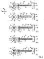
- FIG. 2(A)-(E) the apparatus 10 is illustrated with a first disc 12 seated within the first groove 22 of the support 16, and the second disc 12' being retrieved and stacked onto the support 16.
- Figure 2(A) shows the arm 18 being extended through the aperture 14 of the second disc 12'. While the arm 18 is being extended in direction A, it is kept retracted within the channel 20, such as not to engage the first disc 12 seated on the support 16.
- the arm 18 is again lowered into the channel 20 in direction B, thereby resulting in the first and second discs 12, 12' each being lowered into adjacent grooves 22 on the support 16, such as to again return the apparatus 10 to it's initial configuration.
- the above sequence may then be repeated by again extending the arm 18 such as to retrieve a third disc 12". It will therefore be appreciated that as the above sequence is repeated, the plurality of discs 12 will be simultaneously moved rearwardly along the support 16, one groove 22 at a time, towards the body 26.
- the apparatus 10 is therefore provided with a sensor 30 mounted to the body 26, which sensor 30 is adapted to detect when the final groove 22 on the support 16 has been filled with a disc 12, thereby indicating that all of the grooves 22 on the support 16 have been filled.
- the sensor 30 is adapted to generate a signal which may terminate operation of the apparatus 10, generate a signal to which an operator responds, or displace the apparatus 10 to a new location within the assembly line (not shown).
- the sensor 30 preferably operates as a proximity detector, utilising conventional infrared or ultrasonic technology or the like, although the sensor 30 could be of any other suitable type.
- the last groove 22 in the support 16 could be provided with a pressure sensor (not shown) or the like disposed therein, which would therefore be operable to determine when the groove 22 had been filled with a disc 12.
- the above sequence may be reversed in order to unload the discs 12 from the apparatus 10 to any given location.
- Such reversal of the above sequence would preferably be effected by computer control, for example following transport of the loaded apparatus 10 to another location at which the discs 12 are required.
- an object handling apparatus generally indicated as 110, embodying the invention and for use in stacking and/or unloading objects such as discs 112 from an off horizontal, preferably vertical, orientation.
- like components have been accorded like reference numerals, and unless otherwise stated, perform a like function.
- the apparatus 110 essentially comprises a support in the form of a first pair of jaws 116, and an arm in the form of a second pair of jaws 118 located in parallel spaced relation to the first jaws 116.
- the first jaws 116 are mounted to a body 126, while the second jaws 118 are mounted to a base 128 disposed within the body 126.
- the apparatus 110 is provided with control circuitry (not shown) comprising electrical components (e.g. servo motors), hydraulic or pneumatic rams (not shown) or any other functional equivalents, in order to power the apparatus 110.
- control circuitry (not shown) is operable to control the movement of the first jaws 116 relative to one another and the second jaws 118, and the second jaws 118 relative to one another and the first jaws 116.
- the apparatus 110 operates on the same basic principal as the apparatus 10 of the first embodiment, with a number of variations described hereunder, in order to enable the apparatus 110 to operate in a non-horizontal position. The apparatus 110 is therefore not dependent on gravity to hold the discs 112 in position thereon.
- the apparatus 110 is located such that the free ends of the first jaws 116 and second jaws 118 are located proximal an aperture 114 of the disc 112 to be stacked.
- the second jaws 118 are extended in a direction A such as to pass through the aperture 114 until a first set of indentations 124 are disposed coplanar with the disc 112.
- the second jaws 118 are then advanced away from one another, in a direction B substantially perpendicular to direction A, such as to engage a rim 115 of the aperture 114, at a pair of oppositely disposed points, as defined by the first set of indentations 124.
- the second jaws 118 are then retracted in direction A, as illustrated in Figure 3(D) , such as to effectively draw the first jaws 118 through the aperture 114 of the disc 112, until the rim 115 of the disc 112 is aligned with a first set of grooves 122 on the first jaws 116.
- the first jaws 116 are disposed in close proximity with one another in order to prevent fouling thereof with the rim 115.
- the first jaws 116 are then advanced, as illustrated in Figure 3(E) , away from one another in a direction C substantially perpendicular to both direction A and B, such as to engage the rim 115 of the aperture 114.
- the second jaws 118 may then be advanced towards one another in direction B such as to disengage the disc 112, which is then supported solely by the first jaws 116.
- the first jaws 116 and the second jaws 118 should be displaced towards and away from each disc 112 in a direction substantially parallel to the plane of the disc 112, in order to prevent any unwanted movement between the disc 112 and the apparatus 110.
- the above sequence may then be repeated to stack a second disk 112' and subsequent discs 112.
- the second jaws 118 are advanced in direction A through the aperture 114 of the second disc 112'.
- the second jaws 118 are then advanced away from one another in direction B such as to engage both the first and second discs 112, 112' in respective indentations 124.
- the first jaws 116 are then advanced towards one another in direction C such as to disengage the first disc 112.
- the second jaws 118 are then retracted in direction A such as to draw the second disc 112' over the first jaws 116. This retraction of the second jaws 118 also draws the first disc 112 further along the first jaws 116.
- the first jaws 116 are then advanced away from one another in direction C such as to engage both the first and second disc 112, 112' within respective grooves 122, wherein the second jaws 118 are advanced towards one another in direction B such as to disengage the first and second discs 112, 112'.
- the first and second discs 112, 112' are each engaged in a respective groove 122 of each of the first jaws 116, such as to retain the discs 112, 112' stacked in position on the apparatus 110.
- the above sequence may then be repeated to stack further discs 112 onto the apparatus 110, each sequence advancing the plurality of discs 112 upwardly along the first jaws 116.
- the apparatus 110 is also provided with a sensor 130, mounted to the body 126 and located proximal the final grooves 22 on the first jaws 116, such as to detect the presence of a disc 112 in said grooves 122, and thus generate an appropriate signal to cease operation of the apparatus 110, and optionally transfer the discs 112, 112', 112" to another location for unloading.
- a sensor 130 mounted to the body 126 and located proximal the final grooves 22 on the first jaws 116, such as to detect the presence of a disc 112 in said grooves 122, and thus generate an appropriate signal to cease operation of the apparatus 110, and optionally transfer the discs 112, 112', 112" to another location for unloading.
- both the first jaws 116 and the second jaws 118 may be provided with a layer or coating of protective material, for example rubber or the like, to reduce the possibility of damage to the discs 112 during operation of the apparatus 110.
- the apparatus 110 is primarily intended to vertically stack discs 112, it could of course be applied to discs (not shown) in any orientation, including horizontal. It will therefore also be appreciated that the apparatus 110 could be utilised to stack discs 112 which are presented to the apparatus 110 at one orientation, and which discs 112 could subsequently be unloaded from the apparatus 110 at an alternative orientation, which would not be possible with the apparatus 10 of the first embodiment. Therefore, although the configuration and operation of the apparatus 110 is slightly more complex than that of the first embodiment, the apparatus 110 does provided greater versatility.
Landscapes
- Engineering & Computer Science (AREA)
- Mechanical Engineering (AREA)
- Manufacturing Optical Record Carriers (AREA)
- Polarising Elements (AREA)
- Manipulator (AREA)
- Press Drives And Press Lines (AREA)
- Specific Conveyance Elements (AREA)
- Sheets, Magazines, And Separation Thereof (AREA)
- Reciprocating Conveyors (AREA)
- Automatic Disk Changers (AREA)
Claims (9)
- Vorrichtung (110) zum Handhaben von Gegenständen (112), wobei jeder Gegenstand eine darin enthaltene Öffnung (114) aufweist, die einen Rand (115) begrenzt, wobei die Vorrichtung Folgendes aufweist: einen ersten Satz von Backen (118), die zueinander hin und voneinander weg bewegt werden können; Mittel zum Bewirken des Ausfahrens der Backen des ersten Satzes durch die Öffnung mindestens eines der Gegenstände, Verschiebung der Backen des ersten Satzes voneinander weg in Eingriff mit dem Rand des mindestens einen der Gegenstände, und Verschiebung der Backen des ersten Satzes zueinander hin, dadurch gekennzeichnet, dass die Vorrichtung weiter einen zweiten Satz von Backen (116) einschließt, die zueinander hin und voneinander weg bewegt werden können, wobei der zweite Backensatz einen Träger bereitstellt, auf dem in Gebrauch einer oder mehrere der Gegenstände gestapelt werden oder von dem dieselben entladen werden können, wobei der erste Backensatz angrenzend an den zweiten Backensatz angeordnet ist, so dass in Gebrauch der erste Backensatz und der zweite Backensatz durch die Öffnung hindurchgehen können; Mittel zum Zurückziehen des ersten Backensatzes, um so den Rand über dem zweiten Backensatz zu positionieren; und Mittel zum Antreiben der Backen des zweiten Satzes voneinander weg in Eingriff mit dem Rand, und zum Antreiben der Backen des zweiten Satzes zueinander hin.
- Vorrichtung zum Handhaben von Gegenständen nach Anspruch 1, bei dem der erste und zweite Backensatz länglich sind, und im Wesentlichen parallel zueinander sind.
- Vorrichtung zum Handhaben von Gegenständen nach Anspruch 1 oder 2, bei der der erste Backensatz mit einer Mehrzahl von Einkerbungen (124) versehen ist, die mit Abstand entlang der Länge desselben vorgesehen sind.
- Vorrichtung zum Handhaben von Gegenständen nach einem der Ansprüche 1 bis 3, bei der der zweite Backensatz mit einer Mehrzahl von Einkerbungen (122) versehen ist, die mit Abstand entlang der Länge desselben vorgesehen sind.
- Vorrichtung zum Handhaben von Gegenständen nach einem jeglichen vorhergehenden Anspruch, wobei die Vorrichtung mit einem Sensor (130) versehen ist, der zum Erkennen angepasst ist, wenn eine vorgegebene Anzahl der Gegenstände auf dem Träger gestapelt worden ist.
- Vorrichtung zum Handhaben von Gegenständen nach einem vorhergehenden Anspruch, bei der die Backen des ersten Satzes in einer Richtung zueinander hin und voneinander weg bewegt werden können, die im Wesentlichen senkrecht zu der Richtung ist, in der die Backen des zweiten Satzes zueinander hin und voneinander weg bewegt werden können.
- Verfahren zum Handhaben von Gegenständen (112) in einer Vorrichtung (110) nach einem der Ansprüche 1 bis 6, wobei jeder Gegenstand eine darin vorgesehene Öffnung (114) aufweist, die einen Rand (115) begrenzt, wobei das Verfahren Folgendes umfasst: Ausfahren des ersten Backensatzes durch die Öffnung mindestens eines der Gegenstände, Verschieben der Backen des ersten Satzes voneinander weg in Eingriff mit dem Rand des mindestens einen der Gegenstände, dadurch gekennzeichnet, dass das Verfahren weiter Folgendes umfasst: Zurückziehen des ersten Backensatzes, um so den Rand über dem zweiten Backensatz zu positionieren; Verschieben der Backen des zweiten Satzes voneinander weg, um den Rand zu ergreifen; und Verschieben der Backen des ersten Satzes zueinander hin.
- Verfahren nach Anspruch 7, bei dem die Backen des ersten Satzes durch die Öffnung entlang einer ersten Achse ausgefahren werden können und entlang einer zweiten Achse zueinander hin und voneinander weg bewegt werden können, wobei die erste und zweite Achse im Wesentlichen senkrecht zueinander sind.
- Verfahren nach Anspruch 8, bei dem die Backen des zweiten Satzes entlang einer dritten Achse zueinander hin und voneinander weg bewegt werden können, die im Wesentlichen senkrecht zu der ersten Achse und der zweiten Achse ist.
Applications Claiming Priority (3)
| Application Number | Priority Date | Filing Date | Title |
|---|---|---|---|
| GB0215419 | 2002-07-04 | ||
| GBGB0215419.3A GB0215419D0 (en) | 2002-07-04 | 2002-07-04 | Object handling apparatus and method |
| PCT/EP2003/007262 WO2004004983A2 (en) | 2002-07-04 | 2003-07-04 | Apparatus and method for handling discs provided with an aperture |
Publications (2)
| Publication Number | Publication Date |
|---|---|
| EP1522074A2 EP1522074A2 (de) | 2005-04-13 |
| EP1522074B1 true EP1522074B1 (de) | 2008-10-22 |
Family
ID=9939795
Family Applications (1)
| Application Number | Title | Priority Date | Filing Date |
|---|---|---|---|
| EP03762638A Expired - Lifetime EP1522074B1 (de) | 2002-07-04 | 2003-07-04 | Vorrichtung und verfahren zur handhabung von platten |
Country Status (9)
| Country | Link |
|---|---|
| US (1) | US7320491B2 (de) |
| EP (1) | EP1522074B1 (de) |
| JP (1) | JP2005531473A (de) |
| AT (1) | ATE412240T1 (de) |
| AU (1) | AU2003250900A1 (de) |
| DE (1) | DE60324282D1 (de) |
| GB (1) | GB0215419D0 (de) |
| MY (1) | MY138078A (de) |
| WO (1) | WO2004004983A2 (de) |
Families Citing this family (1)
| Publication number | Priority date | Publication date | Assignee | Title |
|---|---|---|---|---|
| US10240903B2 (en) * | 2016-01-14 | 2019-03-26 | Action Target Inc. | Projectile collection system |
Family Cites Families (10)
| Publication number | Priority date | Publication date | Assignee | Title |
|---|---|---|---|---|
| US4290734A (en) * | 1980-05-19 | 1981-09-22 | Dysan Corporation | Rigid disc handling device and method |
| US4354603A (en) * | 1980-10-14 | 1982-10-19 | Dysan Corporation | Rigid magnetic disc stacker |
| JPS60236929A (ja) * | 1984-05-09 | 1985-11-25 | Eguchi Menki Seisakusho:Kk | 箱移送装置 |
| US4645401A (en) * | 1984-06-13 | 1987-02-24 | Disc Technology Corporation | Magnetic disc handling system |
| US4865509A (en) | 1987-10-29 | 1989-09-12 | Phase 2 Automation | Walking beam gripper |
| JPH04119526A (ja) * | 1990-09-10 | 1992-04-21 | Hitachi Electron Eng Co Ltd | ディスク移載装置 |
| US5259719A (en) * | 1991-12-30 | 1993-11-09 | Intelmatec Corporation | Apparatus for transferring disks between a cassette and a pallet |
| JPH0563788U (ja) * | 1992-02-03 | 1993-08-24 | 新明和工業株式会社 | ディスクのチャック装置 |
| JPH05318375A (ja) | 1992-05-25 | 1993-12-03 | Nec Corp | ロボットハンド |
| JPH07153073A (ja) | 1993-12-01 | 1995-06-16 | Kawasaki Heavy Ind Ltd | ディスク装着システム |
-
2002
- 2002-07-04 GB GBGB0215419.3A patent/GB0215419D0/en not_active Ceased
-
2003
- 2003-07-04 JP JP2004518725A patent/JP2005531473A/ja active Pending
- 2003-07-04 DE DE60324282T patent/DE60324282D1/de not_active Expired - Fee Related
- 2003-07-04 EP EP03762638A patent/EP1522074B1/de not_active Expired - Lifetime
- 2003-07-04 US US10/520,247 patent/US7320491B2/en not_active Expired - Fee Related
- 2003-07-04 AU AU2003250900A patent/AU2003250900A1/en not_active Abandoned
- 2003-07-04 WO PCT/EP2003/007262 patent/WO2004004983A2/en not_active Ceased
- 2003-07-04 AT AT03762638T patent/ATE412240T1/de not_active IP Right Cessation
- 2003-07-04 MY MYPI20032529A patent/MY138078A/en unknown
Also Published As
| Publication number | Publication date |
|---|---|
| EP1522074A2 (de) | 2005-04-13 |
| MY138078A (en) | 2009-04-30 |
| ATE412240T1 (de) | 2008-11-15 |
| AU2003250900A1 (en) | 2004-01-23 |
| WO2004004983A3 (en) | 2004-04-15 |
| GB0215419D0 (en) | 2002-08-14 |
| DE60324282D1 (de) | 2008-12-04 |
| US7320491B2 (en) | 2008-01-22 |
| WO2004004983A2 (en) | 2004-01-15 |
| JP2005531473A (ja) | 2005-10-20 |
| AU2003250900A8 (en) | 2004-01-23 |
| US20050232738A1 (en) | 2005-10-20 |
Similar Documents
| Publication | Publication Date | Title |
|---|---|---|
| CN101715381B (zh) | 板材切割中心的装载/卸载系统、其送料盘和装卸方法 | |
| JP2598551B2 (ja) | 物体を基板から取り出すための運搬装置 | |
| KR100638942B1 (ko) | 각각의 웨이퍼를 처리하기 위한 장치 및 방법 | |
| US20110033270A1 (en) | Displaceable lift truck equipped with releasable engaging means for making up a mixed pack of slab material and method associated therewith | |
| US20180195246A1 (en) | Deploying marker objects | |
| US2841300A (en) | Method of and means for handling coils of wire | |
| JPH1050804A (ja) | 独立リニアデュアルブレードロボット及び搬送方法 | |
| GB1559973A (en) | Depalletizer | |
| US20060269389A1 (en) | Handling unit for palletizing | |
| CN113305819A (zh) | 一种物流搬运用的机械臂 | |
| AU2024287219A1 (en) | Retractor Gripper | |
| EP1522074B1 (de) | Vorrichtung und verfahren zur handhabung von platten | |
| WO2006021678A1 (fr) | Poste de realisation d'un travail sur une piece | |
| CN117284679A (zh) | 取物机构、物品搬运方法及搬运机器人 | |
| US5465476A (en) | HDA headload carriage tooling | |
| CN118684004B (zh) | 一种基于视觉的码垛控制系统及方法 | |
| US20070018469A1 (en) | Contamination-free edge gripping mechanism with withdrawable pads and method for loading/unloading and transferring flat objects | |
| LU86458A1 (fr) | Installation automatisee pour briqueter la paroi interieure d'une enceinte | |
| JP2857097B2 (ja) | 真空処理装置 | |
| JPH04116022A (ja) | ワークストッカ | |
| CN118514099A (zh) | 一种钻取式抓取不规则物体的装置及方法 | |
| JP3261513B2 (ja) | 荷積み装置及びその方法 | |
| JPH05139316A (ja) | 筒状又は柱状の物体の運搬装置 | |
| FR2823188A1 (fr) | Methode et manipulateur pour le transfert de supports de composants electroniques et/ou informatiques conformes en disques | |
| JP3211953B2 (ja) | シールドセグメントの坑内ストック・移送・積出し法及び施設 |
Legal Events
| Date | Code | Title | Description |
|---|---|---|---|
| PUAI | Public reference made under article 153(3) epc to a published international application that has entered the european phase |
Free format text: ORIGINAL CODE: 0009012 |
|
| 17P | Request for examination filed |
Effective date: 20050204 |
|
| AK | Designated contracting states |
Kind code of ref document: A2 Designated state(s): AT BE BG CH CY CZ DE DK EE ES FI FR GB GR HU IE IT LI LU MC NL PT RO SE SI SK TR |
|
| AX | Request for extension of the european patent |
Extension state: AL LT LV MK |
|
| DAX | Request for extension of the european patent (deleted) | ||
| 17Q | First examination report despatched |
Effective date: 20061222 |
|
| GRAP | Despatch of communication of intention to grant a patent |
Free format text: ORIGINAL CODE: EPIDOSNIGR1 |
|
| GRAS | Grant fee paid |
Free format text: ORIGINAL CODE: EPIDOSNIGR3 |
|
| GRAA | (expected) grant |
Free format text: ORIGINAL CODE: 0009210 |
|
| AK | Designated contracting states |
Kind code of ref document: B1 Designated state(s): AT BE BG CH CY CZ DE DK EE ES FI FR GB GR HU IE IT LI LU MC NL PT RO SE SI SK TR |
|
| REG | Reference to a national code |
Ref country code: GB Ref legal event code: FG4D |
|
| REG | Reference to a national code |
Ref country code: CH Ref legal event code: EP |
|
| REG | Reference to a national code |
Ref country code: IE Ref legal event code: FG4D |
|
| REF | Corresponds to: |
Ref document number: 60324282 Country of ref document: DE Date of ref document: 20081204 Kind code of ref document: P |
|
| NLV1 | Nl: lapsed or annulled due to failure to fulfill the requirements of art. 29p and 29m of the patents act | ||
| PG25 | Lapsed in a contracting state [announced via postgrant information from national office to epo] |
Ref country code: BG Free format text: LAPSE BECAUSE OF FAILURE TO SUBMIT A TRANSLATION OF THE DESCRIPTION OR TO PAY THE FEE WITHIN THE PRESCRIBED TIME-LIMIT Effective date: 20090122 Ref country code: AT Free format text: LAPSE BECAUSE OF FAILURE TO SUBMIT A TRANSLATION OF THE DESCRIPTION OR TO PAY THE FEE WITHIN THE PRESCRIBED TIME-LIMIT Effective date: 20081022 Ref country code: ES Free format text: LAPSE BECAUSE OF FAILURE TO SUBMIT A TRANSLATION OF THE DESCRIPTION OR TO PAY THE FEE WITHIN THE PRESCRIBED TIME-LIMIT Effective date: 20090202 |
|
| PG25 | Lapsed in a contracting state [announced via postgrant information from national office to epo] |
Ref country code: NL Free format text: LAPSE BECAUSE OF FAILURE TO SUBMIT A TRANSLATION OF THE DESCRIPTION OR TO PAY THE FEE WITHIN THE PRESCRIBED TIME-LIMIT Effective date: 20081022 Ref country code: FI Free format text: LAPSE BECAUSE OF FAILURE TO SUBMIT A TRANSLATION OF THE DESCRIPTION OR TO PAY THE FEE WITHIN THE PRESCRIBED TIME-LIMIT Effective date: 20081022 Ref country code: SI Free format text: LAPSE BECAUSE OF FAILURE TO SUBMIT A TRANSLATION OF THE DESCRIPTION OR TO PAY THE FEE WITHIN THE PRESCRIBED TIME-LIMIT Effective date: 20081022 Ref country code: PT Free format text: LAPSE BECAUSE OF FAILURE TO SUBMIT A TRANSLATION OF THE DESCRIPTION OR TO PAY THE FEE WITHIN THE PRESCRIBED TIME-LIMIT Effective date: 20090323 |
|
| PG25 | Lapsed in a contracting state [announced via postgrant information from national office to epo] |
Ref country code: DK Free format text: LAPSE BECAUSE OF FAILURE TO SUBMIT A TRANSLATION OF THE DESCRIPTION OR TO PAY THE FEE WITHIN THE PRESCRIBED TIME-LIMIT Effective date: 20081022 Ref country code: EE Free format text: LAPSE BECAUSE OF FAILURE TO SUBMIT A TRANSLATION OF THE DESCRIPTION OR TO PAY THE FEE WITHIN THE PRESCRIBED TIME-LIMIT Effective date: 20081022 Ref country code: BE Free format text: LAPSE BECAUSE OF FAILURE TO SUBMIT A TRANSLATION OF THE DESCRIPTION OR TO PAY THE FEE WITHIN THE PRESCRIBED TIME-LIMIT Effective date: 20081022 Ref country code: RO Free format text: LAPSE BECAUSE OF FAILURE TO SUBMIT A TRANSLATION OF THE DESCRIPTION OR TO PAY THE FEE WITHIN THE PRESCRIBED TIME-LIMIT Effective date: 20081022 |
|
| PLBE | No opposition filed within time limit |
Free format text: ORIGINAL CODE: 0009261 |
|
| STAA | Information on the status of an ep patent application or granted ep patent |
Free format text: STATUS: NO OPPOSITION FILED WITHIN TIME LIMIT |
|
| PG25 | Lapsed in a contracting state [announced via postgrant information from national office to epo] |
Ref country code: IT Free format text: LAPSE BECAUSE OF FAILURE TO SUBMIT A TRANSLATION OF THE DESCRIPTION OR TO PAY THE FEE WITHIN THE PRESCRIBED TIME-LIMIT Effective date: 20081022 Ref country code: CZ Free format text: LAPSE BECAUSE OF FAILURE TO SUBMIT A TRANSLATION OF THE DESCRIPTION OR TO PAY THE FEE WITHIN THE PRESCRIBED TIME-LIMIT Effective date: 20081022 Ref country code: SE Free format text: LAPSE BECAUSE OF FAILURE TO SUBMIT A TRANSLATION OF THE DESCRIPTION OR TO PAY THE FEE WITHIN THE PRESCRIBED TIME-LIMIT Effective date: 20090122 |
|
| 26N | No opposition filed |
Effective date: 20090723 |
|
| PG25 | Lapsed in a contracting state [announced via postgrant information from national office to epo] |
Ref country code: SK Free format text: LAPSE BECAUSE OF FAILURE TO SUBMIT A TRANSLATION OF THE DESCRIPTION OR TO PAY THE FEE WITHIN THE PRESCRIBED TIME-LIMIT Effective date: 20081022 |
|
| PGFP | Annual fee paid to national office [announced via postgrant information from national office to epo] |
Ref country code: IE Payment date: 20090722 Year of fee payment: 7 |
|
| PGFP | Annual fee paid to national office [announced via postgrant information from national office to epo] |
Ref country code: GB Payment date: 20090722 Year of fee payment: 7 |
|
| PG25 | Lapsed in a contracting state [announced via postgrant information from national office to epo] |
Ref country code: MC Free format text: LAPSE BECAUSE OF NON-PAYMENT OF DUE FEES Effective date: 20090731 |
|
| REG | Reference to a national code |
Ref country code: CH Ref legal event code: PL |
|
| REG | Reference to a national code |
Ref country code: FR Ref legal event code: ST Effective date: 20100331 |
|
| PG25 | Lapsed in a contracting state [announced via postgrant information from national office to epo] |
Ref country code: FR Free format text: LAPSE BECAUSE OF NON-PAYMENT OF DUE FEES Effective date: 20090731 Ref country code: LI Free format text: LAPSE BECAUSE OF NON-PAYMENT OF DUE FEES Effective date: 20090731 Ref country code: CH Free format text: LAPSE BECAUSE OF NON-PAYMENT OF DUE FEES Effective date: 20090731 |
|
| PG25 | Lapsed in a contracting state [announced via postgrant information from national office to epo] |
Ref country code: DE Free format text: LAPSE BECAUSE OF NON-PAYMENT OF DUE FEES Effective date: 20100202 |
|
| PG25 | Lapsed in a contracting state [announced via postgrant information from national office to epo] |
Ref country code: GR Free format text: LAPSE BECAUSE OF FAILURE TO SUBMIT A TRANSLATION OF THE DESCRIPTION OR TO PAY THE FEE WITHIN THE PRESCRIBED TIME-LIMIT Effective date: 20090123 |
|
| GBPC | Gb: european patent ceased through non-payment of renewal fee |
Effective date: 20100704 |
|
| PG25 | Lapsed in a contracting state [announced via postgrant information from national office to epo] |
Ref country code: LU Free format text: LAPSE BECAUSE OF NON-PAYMENT OF DUE FEES Effective date: 20090704 |
|
| PG25 | Lapsed in a contracting state [announced via postgrant information from national office to epo] |
Ref country code: HU Free format text: LAPSE BECAUSE OF FAILURE TO SUBMIT A TRANSLATION OF THE DESCRIPTION OR TO PAY THE FEE WITHIN THE PRESCRIBED TIME-LIMIT Effective date: 20090423 |
|
| PG25 | Lapsed in a contracting state [announced via postgrant information from national office to epo] |
Ref country code: GB Free format text: LAPSE BECAUSE OF NON-PAYMENT OF DUE FEES Effective date: 20100704 Ref country code: IE Free format text: LAPSE BECAUSE OF NON-PAYMENT OF DUE FEES Effective date: 20100705 |
|
| PG25 | Lapsed in a contracting state [announced via postgrant information from national office to epo] |
Ref country code: TR Free format text: LAPSE BECAUSE OF FAILURE TO SUBMIT A TRANSLATION OF THE DESCRIPTION OR TO PAY THE FEE WITHIN THE PRESCRIBED TIME-LIMIT Effective date: 20081022 |
|
| PG25 | Lapsed in a contracting state [announced via postgrant information from national office to epo] |
Ref country code: CY Free format text: LAPSE BECAUSE OF FAILURE TO SUBMIT A TRANSLATION OF THE DESCRIPTION OR TO PAY THE FEE WITHIN THE PRESCRIBED TIME-LIMIT Effective date: 20081022 |