EP1520982B1 - Brennstoffeinspritzventil - Google Patents
Brennstoffeinspritzventil Download PDFInfo
- Publication number
- EP1520982B1 EP1520982B1 EP04023132A EP04023132A EP1520982B1 EP 1520982 B1 EP1520982 B1 EP 1520982B1 EP 04023132 A EP04023132 A EP 04023132A EP 04023132 A EP04023132 A EP 04023132A EP 1520982 B1 EP1520982 B1 EP 1520982B1
- Authority
- EP
- European Patent Office
- Prior art keywords
- fuel injection
- injection valve
- seal
- fuel
- valve according
- Prior art date
- Legal status (The legal status is an assumption and is not a legal conclusion. Google has not performed a legal analysis and makes no representation as to the accuracy of the status listed.)
- Expired - Lifetime
Links
- 239000000446 fuel Substances 0.000 title claims description 56
- 238000002347 injection Methods 0.000 claims description 40
- 239000007924 injection Substances 0.000 claims description 40
- 239000011324 bead Substances 0.000 claims description 9
- 238000002485 combustion reaction Methods 0.000 claims description 8
- 239000013013 elastic material Substances 0.000 claims description 2
- 238000007789 sealing Methods 0.000 description 13
- 230000000694 effects Effects 0.000 description 2
- 238000010276 construction Methods 0.000 description 1
- 230000001419 dependent effect Effects 0.000 description 1
- 238000011161 development Methods 0.000 description 1
- 230000018109 developmental process Effects 0.000 description 1
- 229920001971 elastomer Polymers 0.000 description 1
- 239000000806 elastomer Substances 0.000 description 1
- 238000005538 encapsulation Methods 0.000 description 1
- 238000001125 extrusion Methods 0.000 description 1
- 238000007765 extrusion coating Methods 0.000 description 1
- 238000001914 filtration Methods 0.000 description 1
- 238000009434 installation Methods 0.000 description 1
- 238000003466 welding Methods 0.000 description 1
Images

Classifications
-
- F—MECHANICAL ENGINEERING; LIGHTING; HEATING; WEAPONS; BLASTING
- F02—COMBUSTION ENGINES; HOT-GAS OR COMBUSTION-PRODUCT ENGINE PLANTS
- F02M—SUPPLYING COMBUSTION ENGINES IN GENERAL WITH COMBUSTIBLE MIXTURES OR CONSTITUENTS THEREOF
- F02M61/00—Fuel-injectors not provided for in groups F02M39/00 - F02M57/00 or F02M67/00
- F02M61/14—Arrangements of injectors with respect to engines; Mounting of injectors
- F02M61/145—Arrangements of injectors with respect to engines; Mounting of injectors the injection nozzle opening into the air intake conduit
Definitions
- the invention relates to a fuel injection valve according to the preamble of claim 1.
- Fuel injection valves for the injection of fuel into a suction pipe of an internal combustion engine usually have a seal in the downstream region of the valve housing, whereby it is sealed against the intake manifold.
- Such a seal is for example from the DE 26 53 674 A1 known.
- the seal is on the one hand put over the fuel injection valve and on the other hand via a connection piece of the suction tube and bellows-shaped.
- a gasket for sealing a fuel injection valve to a suction pipe of an internal combustion engine is known.
- a tip of the fuel injection valve is arranged in a cup-shaped seal, which bears against a wall of the suction tube.
- a disadvantage of the seals described is in particular that they only conditionally mid-misalignments of Fuel injector can compensate. If such a center offset, transverse forces acting on the fuel injection valve, which u. U. lead to the sealing effect of the seal is no longer guaranteed.
- the GB-A-2 022 727 discloses a fuel injector which is fixed by a sleeve made of an elastomer in a bore which leads to an inlet passage of a cylinder head or an intake pipe.
- An outer end portion of the sleeve has an annular bead which projects radially inwardly and outwardly.
- a radially inwardly projecting rib portion of the annular bead engages an annular recess of the injector and the radially outwardly extending rib portion of the annular bead engages another flatter annular recess in the bore.
- Another annular rib is formed at the inner end portion of the sleeve on the radially inner side of the sleeve.
- the fuel injection valve according to the invention with the features of claim 1 has the advantage that the seal a bead and having a collar formed thereon with folded edge, wherein in the folded edge, a support ring is integrated, which has an L-shaped profile and on the one hand enables the stability and on the other hand, a center offset compensating function of the seal.
- the sleeve is funnel-shaped and made of an elastic material. As a result, center offsets of the fuel injection valve can be easily compensated without affecting the sealing effect of the seal.
- the bead engages in a constriction of the fuel injection valve and is fixed there by means of a ring.
- the suction tube may advantageously have a chamfer.
- Fig. 1 shows for clarity of the inventive measures first in a fragmentary, schematic sectional view of a longitudinal section through the discharge-side part of a fuel injection valve 1 according to the prior art, which is particularly suitable for injecting fuel into a not-shown suction manifold of an internal combustion engine.
- the fuel injection valve 1 comprises a magnetic coil 2 which is wound on a bobbin 3.
- the bobbin 3 is encapsulated in a valve housing 4.
- the bobbin 3 is penetrated by a valve sleeve 5, which is tubular and includes therein a spread or welded support tube 6, which serves as the inner pole of the magnetic coil 2.
- a valve sleeve 5 which is tubular and includes therein a spread or welded support tube 6, which serves as the inner pole of the magnetic coil 2.
- the valve housing 4 serve.
- armature 7 Downstream of the support tube 6, an armature 7 is arranged, which is formed integrally with a valve needle 8.
- through-flow openings 9 are provided which guide the fuel injector 1 flowing through the fuel to a sealing seat.
- a ring filter 10 may be arranged for filtering the fuel.
- the valve needle 8 is preferably by welding in operative connection with a spherical valve closure member 11 in the embodiment, which forms a sealing seat with a valve seat body 12. Downstream of the sealing seat, at least one spray-discharge opening 14 is formed in a spray-disk 13, from which the fuel is injected into the suction pipe (not shown).
- the armature 9 is acted upon in the idle state of the fuel injection valve 1 by a return spring 15 so that the fuel injection valve 1 is kept closed by the pressure of the valve closing body 11 on the valve seat body 12.
- the return spring 15 is arranged in a recess 16 of the armature 7 and the support tube 6 and is brought by an adjusting sleeve 17 to bias.
- a cup-shaped filter element 18 is preferably pressed into the valve sleeve 5.
- the fuel which is supplied through a central fuel supply 19, flows through the fuel injection valve 1 through the recess 16 and the throughflow openings 9 to the sealing seat and to the injection opening 14.
- the fuel injection valve 1 is closed as soon as the magnetic coil 2 exciting current is turned off and the magnetic field is reduced so far that the return spring 15 pushes the armature 7 from the support tube 6, whereby the valve needle 8 moves in the outflow direction and the valve closing body 11 touches on the valve seat body 12 ,
- a disadvantage of the described sealing ring 21 is in particular that the fuel injector 1 must be installed center-centered, since due to the installation position and the shape of the sealing ring 21 no degrees of freedom for offsets are available.
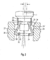
- a in Fig. 2 a partial embodiment of a fuel injection valve 1 designed according to the invention a funnel-shaped seal 24 'instead of the sealing ring 21, which is pushed onto the plastic encapsulation 23.
- the seal 24 'in this case has an annular bead 25, which is pushed onto the plastic extrusion coating 23 and engages in a constriction 26 of the fuel injection valve 1, and an expanding in the outflow funnel-shaped elastic sleeve 27, which has a projecting edge 28 which radially inside is folded.
- a support ring 31 is preferably inserted into the projecting, folded-over edge 28.
- the support ring 31 in this case has a rectangular L-shaped cross-section, the legs 32 are arranged parallel to the outflow direction or perpendicular thereto in the direction of the fuel injection valve 1.
- the support ring 31 ensures that on the one hand the endurance stability of the seal 24 'is guaranteed and that on the other hand, the fuel injector 1 can be operated both in the suction mode and in the charged operation.
- the seal 24 ' is secured by a pushed, preferably metallic ring 33 to the fuel injection valve 1. This ensures that even with charged operation at the bead 25 no leakage occurs.
- the fuel injection valve 1 which is pre-assembled in a modular manner and then inserted into the suction pipe 30, by the elastic seal 24 'align so that it is stored on the one hand without lateral force and on the other hand, the seal 24' can still perform their sealing function. Center offsets of at least ⁇ 1 mm can be compensated, as in Fig. 2 shown.
- the elastic funnel-shaped seal 24 ' is deformed asymmetrically.
- the seal 24 ' is designed so that as many standard parts for the fuel injector can be used to fit in a given Saugrohrgeometrie.
- the suction pipe 30 For ease of mounting the gasket 24 'with the fuel injector 1, the suction pipe 30 on a fuel injection valve 1 side facing a chamfer 34.
- the invention is not limited to the illustrated embodiment and for any construction of fuel injection valves 1, z. B. suitable for fuel injection valves 1 with piezoelectric or magnetostrictive actuators and for use in internal combustion engines for supercharged and intake manifold operation.
- any combinations of the individual features are possible.
Landscapes
- Engineering & Computer Science (AREA)
- Chemical & Material Sciences (AREA)
- Combustion & Propulsion (AREA)
- Mechanical Engineering (AREA)
- General Engineering & Computer Science (AREA)
- Fuel-Injection Apparatus (AREA)
Description
- Die Erfindung geht aus von einem Brennstoffeinspritzventil nach dem Oberbegriff des Anspruchs 1.
- Brennstoffeinspritzventile für die Einspritzung von Brennstoff in ein Saugrohr einer Brennkraftmaschine weisen gewöhnlich eine Dichtung im abströmseitigen Bereich des Ventilgehäuses auf, wodurch dieses gegen das Saugrohr abgedichtet wird.
- Eine solche Dichtung ist beispielsweise aus der
DE 26 53 674 A1 bekannt. Die Dichtung ist dabei einerseits über das Brennstoffeinspritzventil und andererseits über einen Anschlußstutzen des Saugrohrs gestülpt und balgförmig ausgebildet. - Auch aus der
DE 22 08 646 A1 ist eine Dichtung zum Abdichten eines Brennstoffeinspritzventils gegen ein Saugrohr einer Brennkraftmaschine bekannt. Dabei ist eine Spitze des Brennstoffeinspritzventils in einer topfförmigen Dichtung angeordnet, welche an einer Wandung des Saugrohrs anliegt. - Nachteilig an den beschriebenen Dichtungen ist dabei insbesondere, daß sie nur bedingt Mittenversätze des Brennstoffeinspritzventils ausgleichen können. Liegt ein solcher Mittenversatz vor, wirken Querkräfte auf das Brennstoffeinspritzventil, welche u. U. dazu führen, dass die Dichtwirkung der Dichtung nicht mehr gewährleistet ist.
- Insbesondere ist die aus der
DE 26 53 674 A1 bekannte Dichtung nicht für den aufgeladenen Betrieb einer Brennkraftmaschine geeignet, da die Dichtung in dieser Betriebsart große Belastungen erfährt, die im Saugbetrieb nicht auftreten. - Die
GB-A-2 022 727 - Das erfindungsgemäße Brennstoffeinspritzventil mit den Merkmalen des Anspruchs 1 hat demgegenüber den Vorteil, dass die Dichtung einen Wulst und eine daran ausgebildete Manschette mit umgeschlagenen Rand aufweist, wobei in den umgelegten Rand ein Stützring integriert ist, welcher ein L-förmiges Profil aufweist und einerseits die Stabilität und andererseits eine die Mittenversätze ausgleichende Funktion der Dichtung ermöglicht.
- Durch die in den abhängigen Ansprüchen aufgeführten Maßnahmen sind vorteilhafte Weiterentwicklungen und Verbesserungen des im unabhängigen Anspruch 1 angegebenen Brennstoffeinspritzventils möglich.
- Weiterhin ist von Vorteil, dass die Manschette trichterförmig ausgebildet und aus einem elastischen Material hergestellt ist. Dadurch können Mittenversätze des Brennstoffeinspritzventils ohne Beeinträchtigung der Dichtwirkung der Dichtung in einfacher Weise ausgeglichen werden.
- Ebenso ist von Vorteil, daß der Wulst in einer Verengung des Brennstoffeinspritzventils einrastet und dort mittels eines Rings fixiert ist.
- Zur leichteren Montage kann das Saugrohr vorteilhafterweise eine Anfasung aufweisen.
- Ein Ausführungsbeispiel der Erfindung ist in der Zeichnung vereinfacht dargestellt und in der nachfolgenden Beschreibung näher erläutert. Es zeigen:
- Fig. 1
- einen schematischen, auszugsweisen Schnitt durch ein Ausführungsbeispiel eines Brennstoffeinspritzventils gemäß dem Stand der Technik, und
- Fig. 2
- eine schematische, teilgeschnittene Ansicht des abspritzseitigen Endes eines Ausführungsbeispiels eines erfindungsgemäß ausgestalteten Brennstoffeinspritzventils.
-
Fig. 1 zeigt zur besseren Verständlichkeit der erfindungsgemäßen Maßnahmen zunächst in einer ausschnittsweisen, schematisierten Schnittdarstellung einen Längsschnitt durch den abspritzseitigen Teil eines Brennstoffeinspritzventils 1 gemäß dem Stand der Technik, welches insbesondere zum Einspritzen von Brennstoff in ein nicht näher dargestelltes Saugrohr einer Brennkraftmaschine geeignet ist. - Das Brennstoffeinspritzventil 1 umfaßt eine Magnetspule 2, die auf einen Spulenträger 3 gewickelt ist. Der Spulenträger 3 ist in einem Ventilgehäuse 4 gekapselt.
- Der Spulenträger 3 wird von einer Ventilhülse 5 durchgriffen, die rohrförmig ausgestaltet ist und ein darin eingespreiztes oder verschweißtes Stützrohr 6 umfaßt, welches als Innenpol der Magnetspule 2 dient. Als Außenpol der Magnetspule 2 kann beispielsweise das Ventilgehäuse 4 dienen. Abströmseitig des Stützrohres 6 ist ein Anker 7 angeordnet, der einstückig mit einer Ventilnadel 8 ausgebildet ist. In der Ventilnadel 8 sind Durchströmöffnungen 9 vorgesehen, die den das Brennstoffeinspritzventil 1 durchströmenden Brennstoff zu einem Dichtsitz leiten.
- Im Bereich der Durchströmöffnungen 9 kann ein Ringfilter 10 zur Filterung des Brennstoffs angeordnet sein. Die Ventilnadel 8 steht vorzugsweise durch Schweißen in Wirkverbindung mit einem im Ausführungsbeispiel kugelförmigen Ventilschließkörper 11, der mit einem Ventilsitzkörper 12 einen Dichtsitz bildet. Stromabwärts des Dichtsitzes ist in einer Spritzlochscheibe 13 wenigstens eine Abspritzöffnung 14 ausgebildet, aus der der Brennstoff in das nicht weiter dargestellte Saugrohr eingespritzt wird.
- Der Anker 9 ist im Ruhezustand des Brennstoffeinspritzventils 1 von einer Rückstellfeder 15 so beaufschlagt, daß das Brennstoffeinspritzventil 1 durch den Andruck des Ventilschließkörpers 11 auf den Ventilsitzkörper 12 geschlossen gehalten wird. Die Rückstellfeder 15 ist in einer Ausnehmung 16 des Ankers 7 bzw. des Stützrohres 6 angeordnet und wird durch eine Einstellhülse 17 auf Vorspannung gebracht.
- Zulaufseitig der Einstellhülse 17 ist ein topfförmiges Filterelement 18 in die Ventilhülse 5 vorzugsweise eingepreßt. Der Brennstoff, der durch eine zentrale Brennstoffzufuhr 19 zugeleitet wird, durchströmt das Brennstoffeinspritzventil 1 durch die Ausnehmung 16 und die Durchströmöffnungen 9 zum Dichtsitz und zur Abspritzöffnung 14.
- Wird der Magnetspule 2 über eine nicht weiter dargestellte elektrische Leitung ein elektrischer Strom zugeführt, baut sich ein magnetisches Feld auf, das bei ausreichender Stärke den Anker 7 entgegen der Kraft der Rückstellfeder 15 entgegen der Strömungsrichtung des Brennstoffs in die Magnetspule 2 hineinzieht. Dadurch wird ein zwischen dem Anker 7 und dem Stützrohr 6 ausgebildeter Arbeitsspalt 20 geschlossen. Durch die Bewegung des Ankers 7 wird auch die mit dem Anker 7 einstückig ausgebildete Ventilnadel 8 in Hubrichtung mitgenommen, so daß der Ventilschließkörper 11 vom Ventilsitzkörper 12 abhebt und Brennstoff zur Abspritzöffnung 14 geleitet wird.
- Das Brennstoffeinspritzventil 1 wird geschlossen, sobald der die Magnetspule 2 erregende Strom abgeschaltet und das Magnetfeld soweit abgebaut ist, daß die Rückstellfeder 15 den Anker 7 vom Stützrohr 6 abdrückt, wodurch sich die Ventilnadel 8 in Abströmrichtung bewegt und der Ventilschließkörper 11 auf dem Ventilsitzkörper 12 aufsetzt.
- Die Abdichtung des in
Fig. 1 dargestellten Brennstoffeinspritzventils 1 gegen das inFig. 1 nicht näher dargestellte Saugrohr der Brennkraftmaschine erfolgt mittels eines Dichtrings 21, welcher über einen vorkragenden Rand 22 des Ventilgehäuses 4 geschoben und mittels einer Kunststoffumspritzung 23 gegen Abrutschen gesichert ist. - Nachteilig an dem beschriebenen Dichtring 21 ist dabei insbesondere, daß das Brennstoffeinspritzventil 1 mittenzentriert eingebaut werden muß, da bedingt durch die Einbaulage und die Form des Dichtrings 21 keine Freiheitsgrade für Versätze zur Verfügung stehen.
- Demgegenüber weist ein in
Fig. 2 ausschnittsweise dargestelltes Ausführungsbeispiel eines erfindungsgemäß ausgestalteten Brennstoffeinspritzventils 1 eine trichterförmige Dichtung 24' anstelle des Dichtrings 21 auf, welche auf die Kunststoffumspritzung 23 aufgeschoben wird. - Die Dichtung 24' weist dabei einen ringförmigen Wulst 25 auf, welcher auf die Kunststoffumspritzung 23 aufgeschoben wird und in einer Verengung 26 des Brennstoffeinspritzventils 1 einrastet, und eine sich in Abströmrichtung erweiternde trichterförmige elastische Manschette 27, die einen vorkragenden Rand 28 aufweist, der nach radial innen umgelegt ist. Um die Manschette 27 aufzuspannen und in Anlage an einer inneren Wandung 29 eines Saugrohrs 30 zu halten, ist in den vorkragenden, umgelegten Rand 28 vorzugsweise ein Stützring 31 eingelegt. Der Stützring 31 weist dabei einen rechtwinkelig L-förmigen Querschnitt auf, dessen Schenkel 32 parallel zur Abströmrichtung bzw. senkrecht dazu in Richtung auf das Brennstoffeinspritzventil 1 angeordnet sind.
- Der Stützring 31 sorgt dafür, daß einerseits die Dauerlaufstabilität der Dichtung 24' garantiert ist und daß andererseits das Brennstoffeinspritzventil 1 sowohl im Saugbetrieb als auch im aufgeladenen Betrieb betrieben werden kann.
- Die Dichtung 24' ist durch einen aufgeschobenen, vorzugsweise metallischen Ring 33 an dem Brennstoffeinspritzventil 1 gesichert. Dieser stellt sicher, daß auch bei aufgeladenem Betrieb an dem Wulst 25 keine Leckage auftritt.
- Vorteilhafterweise kann sich das Brennstoffeinspritzventil 1, welches modulartig vormontiert und dann in das Saugrohr 30 eingesetzt wird, durch die elastische Dichtung 24' so ausrichten, daß es einerseits querkraftfrei gelagert ist und andererseits die Dichtung 24' immer noch ihre Dichtfunktion ausüben kann. Dabei können Mittenversätze von mindestens ±1 mm ausgeglichen werden, wie in
Fig. 2 dargestellt. Die elastische trichterförmige Dichtung 24' wird dabei asymmetrisch verformt. - Die Dichtung 24' ist dabei so konzipiert, daß möglichst viele serienmäßige Teile für das Brennstoffeinspritzventil verwendet werden können, um in eine gegebene Saugrohrgeometrie zu passen.
- Zur leichteren Montage der Dichtung 24' mit dem Brennstoffeinspritzventil 1 weist das Saugrohr 30 an einer dem Brennstoffeinspritzventil 1 zugewandten Seite eine Anfasung 34 auf.
- Die Erfindung ist nicht auf das dargestellte Ausführungsbeispiel beschränkt und für beliebige Bauweisen von Brennstoffeinspritzventilen 1, z. B. für Brennstoffeinspritzventile 1 mit piezoelektrischen oder magnetostriktiven Aktoren sowie für die Anwendung in Brennkraftmaschinen für aufgeladenen und Saugrohrbetrieb geeignet. Insbesondere sind beliebige Kombinationen der einzelnen Merkmale möglich.
Claims (7)
- Brennstoffeinspritzventil (1) für eine Brennstoffeinspritzanlage einer Brennkraftmaschine mit einem Ventilgehäuse (4),
wobei das Ventilgehäuse (4) durch eine Dichtung (24') gegenüber einer Ventilaufnahme eines Saugrohrs (30) der Brennkraftmaschine abgedichtet ist, und
wobei die Dichtung (24') einen Wulst (25) und eine daran ausgebildete Manschette (27) aufweist, deren vorkragender Rand (28) nach radial innen ragt,
dadurch gekennzeichnet,
dass in den nach radial innen ragenden Rand (28) ein Stützring (31) eingelegt ist, welcher ein L-förmig rechtwinkliges Profil aufweist. - Brennstoffeinspritzventil nach Anspruch 1,
dadurch gekennzeichnet,
dass die Manschette (27) trichterförmig ausgebildet und aus elastischem Material gebildet ist. - Brennstoffeinspritzventil nach Anspruch 1 oder 2,
dadurch gekennzeichnet,
dass der Wulst (25) der Dichtung (24) in eine Verengung (26) des Brennstoffeinspritzventils (1) einrastet. - Brennstoffeinspritzventil nach einem der Ansprüche 1 bis 3,
dadurch gekennzeichnet,
dass die Dichtung (24) mittels eines Rings (33) an dem Brennstoffeinspritzventil (1) gesichert ist. - Brennstoffeinspritzventil nach Anspruch 4,
dadurch gekennzeichnet,
dass der Ring (33) auf die Dichtung (24) und das Brennstoffeinspritzventil (1) aufgeschoben ist. - Brennstoffeinspritzventil nach einem der Ansprüche 1 bis 5,
dadurch gekennzeichnet,
dass die Dichtung (24) an einer inneren Wandung (29) des Saugrohres (30) anliegt. - Brennstoffeinspritzventil nach einem der Ansprüche 1 bis 6,
dadurch gekennzeichnet,
dass die Dichtung (24) den Ausgleich von Mittenversätzen des Brennstoffeinspritzventils (1) gegenüber dem Saugrohr (30) von mindestens +/-1 mm erlaubt.
Applications Claiming Priority (2)
| Application Number | Priority Date | Filing Date | Title |
|---|---|---|---|
| DE10345965 | 2003-10-02 | ||
| DE10345965A DE10345965A1 (de) | 2003-10-02 | 2003-10-02 | Brennstoffeinspritzventil |
Publications (3)
| Publication Number | Publication Date |
|---|---|
| EP1520982A2 EP1520982A2 (de) | 2005-04-06 |
| EP1520982A3 EP1520982A3 (de) | 2005-10-12 |
| EP1520982B1 true EP1520982B1 (de) | 2008-05-21 |
Family
ID=34306239
Family Applications (1)
| Application Number | Title | Priority Date | Filing Date |
|---|---|---|---|
| EP04023132A Expired - Lifetime EP1520982B1 (de) | 2003-10-02 | 2004-09-29 | Brennstoffeinspritzventil |
Country Status (3)
| Country | Link |
|---|---|
| US (1) | US7093585B2 (de) |
| EP (1) | EP1520982B1 (de) |
| DE (2) | DE10345965A1 (de) |
Families Citing this family (4)
| Publication number | Priority date | Publication date | Assignee | Title |
|---|---|---|---|---|
| DE102005052255B4 (de) * | 2005-11-02 | 2020-12-17 | Robert Bosch Gmbh | Brennstoffeinspritzventil |
| US20100148100A1 (en) * | 2008-12-17 | 2010-06-17 | Parker Hannifin Corporation | Media isolated piezo valve |
| DE102009055087A1 (de) * | 2009-12-21 | 2011-06-22 | Robert Bosch GmbH, 70469 | Einspritzventil |
| DE102015225055A1 (de) * | 2015-12-14 | 2017-06-14 | Robert Bosch Gmbh | Kraftstoffinjektor |
Family Cites Families (12)
| Publication number | Priority date | Publication date | Assignee | Title |
|---|---|---|---|---|
| DE2149817B2 (de) * | 1971-10-06 | 1975-08-21 | Daimler-Benz Ag, 7000 Stuttgart | Anordnung eines Kraftstoffeinspritzventils zur elektronisch gesteuerten Benzineinspritzung in den Ansaugkanal einer Brennkraftmaschine |
| US4201172A (en) * | 1972-07-10 | 1980-05-06 | Robert Bosch Gmbh | Fuel injection nozzle assembly for internal combustion engines |
| DE2824476C2 (de) * | 1978-06-03 | 1983-03-17 | Bayerische Motoren Werke AG, 8000 München | Brennstoffeinspritzdüsenbefestigung an einer Brennkraftmaschine |
| DE7827497U1 (de) | 1978-09-15 | 1980-03-06 | Robert Bosch Gmbh, 7000 Stuttgart | Waermeschutz fuer duesen von brennkraftmaschinen |
| DE3000061C2 (de) * | 1980-01-03 | 1993-10-14 | Bosch Gmbh Robert | Kraftstoffeinspritzdüse für Brennkraftmaschinen |
| DE3806906A1 (de) | 1988-03-03 | 1989-09-14 | Opel Adam Ag | Vorrichtung zur befestigung eines in einen saugkanal einer brennkraftmaschine einspritzenden kraftstoffeinspritzventils |
| JPH10281293A (ja) | 1997-04-08 | 1998-10-23 | Nok Corp | 密封装置 |
| DE19743103A1 (de) * | 1997-09-30 | 1999-04-01 | Bosch Gmbh Robert | Wärmeschutzhülse |
| JP3532430B2 (ja) | 1998-12-10 | 2004-05-31 | 三菱電機株式会社 | 燃料噴射弁 |
| DE10027662A1 (de) * | 2000-06-03 | 2001-12-06 | Bosch Gmbh Robert | Dichtmittel und Niederhalter für ein Brennstoffeinspritzventil |
| DE10108194A1 (de) * | 2001-02-21 | 2002-08-29 | Bosch Gmbh Robert | Dichtvorrichtung für ein Brennstoffeinspritzventil |
| ITTO20010787A1 (it) | 2001-08-03 | 2003-02-03 | Rft Spa | Gruppo di iniezione provvisto di tenuta, per un motore a combustione interna. |
-
2003
- 2003-10-02 DE DE10345965A patent/DE10345965A1/de not_active Withdrawn
-
2004
- 2004-09-29 US US10/951,694 patent/US7093585B2/en not_active Expired - Lifetime
- 2004-09-29 EP EP04023132A patent/EP1520982B1/de not_active Expired - Lifetime
- 2004-09-29 DE DE502004007209T patent/DE502004007209D1/de not_active Expired - Lifetime
Also Published As
| Publication number | Publication date |
|---|---|
| DE502004007209D1 (de) | 2008-07-03 |
| EP1520982A3 (de) | 2005-10-12 |
| DE10345965A1 (de) | 2005-07-07 |
| US7093585B2 (en) | 2006-08-22 |
| US20050121001A1 (en) | 2005-06-09 |
| EP1520982A2 (de) | 2005-04-06 |
Similar Documents
| Publication | Publication Date | Title |
|---|---|---|
| EP1651860B1 (de) | Brennstoffeinspritzventil und verfahren zu dessen montage | |
| EP1387942B1 (de) | Brennstoffeinspritzventil mit dämpfungselement | |
| EP1381771B1 (de) | Brennstoffeinspritzventil | |
| EP1697632B1 (de) | Brennstoffeinspritzventil | |
| EP1423603B1 (de) | Brennstoffeinspritzventil | |
| DE102009000183A1 (de) | Brennstoffeinspritzventil | |
| EP1370765B1 (de) | Brennstoffeinspritzventil | |
| DE10108464A1 (de) | Brennstoffeinspritzventil | |
| EP1520982B1 (de) | Brennstoffeinspritzventil | |
| EP3034857B1 (de) | Brennstoffeinspritzventil | |
| EP2884091B1 (de) | Brennstoffeinspritzventil | |
| DE10256661A1 (de) | Brennstoffeinspritzventil | |
| EP1649159B1 (de) | Brennstoffeinspritzventil | |
| EP1797313B1 (de) | Brennstoffeinspritzventil | |
| DE102004047040B4 (de) | Brennstoffeinspritzventil und Verfahren zur Montage eines Brennstoffeinspritzventils | |
| DE102007049945A1 (de) | Brennstoffeinspritzventil | |
| EP1658429B1 (de) | Brennstoffeinspritzventil | |
| DE10133263A1 (de) | Brennstoffeinspritzventil | |
| EP1309790B1 (de) | Brennstoffeinspritzventil | |
| DE102005019313A1 (de) | Brennstoffeinspritzventil | |
| DE102019219628A1 (de) | Ventil zum Zumessen eines Fluids, insbesondere Brennstoffeinspritzventil | |
| DE102020215621A1 (de) | Brennstoffeinspritzventil | |
| DE102008042162A1 (de) | Schnittstelle für Niederdruckleitungen und Brennstoffeinspritzventil mit solch einer Schnittstelle | |
| DE102005044676A1 (de) | Adapter für ein Brennstoffeinspritzventil | |
| DE10338094A1 (de) | Brennstoffeinspritzventil |
Legal Events
| Date | Code | Title | Description |
|---|---|---|---|
| PUAI | Public reference made under article 153(3) epc to a published international application that has entered the european phase |
Free format text: ORIGINAL CODE: 0009012 |
|
| AK | Designated contracting states |
Kind code of ref document: A2 Designated state(s): AT BE BG CH CY CZ DE DK EE ES FI FR GB GR HU IE IT LI LU MC NL PL PT RO SE SI SK TR |
|
| AX | Request for extension of the european patent |
Extension state: AL HR LT LV MK |
|
| PUAL | Search report despatched |
Free format text: ORIGINAL CODE: 0009013 |
|
| AK | Designated contracting states |
Kind code of ref document: A3 Designated state(s): AT BE BG CH CY CZ DE DK EE ES FI FR GB GR HU IE IT LI LU MC NL PL PT RO SE SI SK TR |
|
| AX | Request for extension of the european patent |
Extension state: AL HR LT LV MK |
|
| RIC1 | Information provided on ipc code assigned before grant |
Ipc: 7F 02M 55/00 B Ipc: 7F 02M 61/14 A Ipc: 7F 02M 69/04 B |
|
| 17P | Request for examination filed |
Effective date: 20060412 |
|
| AKX | Designation fees paid |
Designated state(s): DE FR IT |
|
| GRAP | Despatch of communication of intention to grant a patent |
Free format text: ORIGINAL CODE: EPIDOSNIGR1 |
|
| GRAJ | Information related to disapproval of communication of intention to grant by the applicant or resumption of examination proceedings by the epo deleted |
Free format text: ORIGINAL CODE: EPIDOSDIGR1 |
|
| GRAP | Despatch of communication of intention to grant a patent |
Free format text: ORIGINAL CODE: EPIDOSNIGR1 |
|
| GRAS | Grant fee paid |
Free format text: ORIGINAL CODE: EPIDOSNIGR3 |
|
| GRAA | (expected) grant |
Free format text: ORIGINAL CODE: 0009210 |
|
| AK | Designated contracting states |
Kind code of ref document: B1 Designated state(s): DE FR IT |
|
| REF | Corresponds to: |
Ref document number: 502004007209 Country of ref document: DE Date of ref document: 20080703 Kind code of ref document: P |
|
| PLBE | No opposition filed within time limit |
Free format text: ORIGINAL CODE: 0009261 |
|
| STAA | Information on the status of an ep patent application or granted ep patent |
Free format text: STATUS: NO OPPOSITION FILED WITHIN TIME LIMIT |
|
| 26N | No opposition filed |
Effective date: 20090224 |
|
| REG | Reference to a national code |
Ref country code: FR Ref legal event code: PLFP Year of fee payment: 13 |
|
| PGFP | Annual fee paid to national office [announced via postgrant information from national office to epo] |
Ref country code: FR Payment date: 20160922 Year of fee payment: 13 |
|
| PGFP | Annual fee paid to national office [announced via postgrant information from national office to epo] |
Ref country code: IT Payment date: 20160922 Year of fee payment: 13 |
|
| REG | Reference to a national code |
Ref country code: FR Ref legal event code: ST Effective date: 20180531 |
|
| PG25 | Lapsed in a contracting state [announced via postgrant information from national office to epo] |
Ref country code: FR Free format text: LAPSE BECAUSE OF NON-PAYMENT OF DUE FEES Effective date: 20171002 Ref country code: IT Free format text: LAPSE BECAUSE OF NON-PAYMENT OF DUE FEES Effective date: 20170929 |
|
| PGFP | Annual fee paid to national office [announced via postgrant information from national office to epo] |
Ref country code: DE Payment date: 20181121 Year of fee payment: 15 |
|
| REG | Reference to a national code |
Ref country code: DE Ref legal event code: R119 Ref document number: 502004007209 Country of ref document: DE |
|
| PG25 | Lapsed in a contracting state [announced via postgrant information from national office to epo] |
Ref country code: DE Free format text: LAPSE BECAUSE OF NON-PAYMENT OF DUE FEES Effective date: 20200401 |