EP1520163B1 - Verfahren und computerprogramm zum identifizieren eines fehlers in einem motor - Google Patents
Verfahren und computerprogramm zum identifizieren eines fehlers in einem motor Download PDFInfo
- Publication number
- EP1520163B1 EP1520163B1 EP03721198A EP03721198A EP1520163B1 EP 1520163 B1 EP1520163 B1 EP 1520163B1 EP 03721198 A EP03721198 A EP 03721198A EP 03721198 A EP03721198 A EP 03721198A EP 1520163 B1 EP1520163 B1 EP 1520163B1
- Authority
- EP
- European Patent Office
- Prior art keywords
- engine
- speed
- control unit
- engine speed
- computer
- Prior art date
- Legal status (The legal status is an assumption and is not a legal conclusion. Google has not performed a legal analysis and makes no representation as to the accuracy of the status listed.)
- Expired - Lifetime
Links
Images

Classifications
-
- G—PHYSICS
- G01—MEASURING; TESTING
- G01M—TESTING STATIC OR DYNAMIC BALANCE OF MACHINES OR STRUCTURES; TESTING OF STRUCTURES OR APPARATUS, NOT OTHERWISE PROVIDED FOR
- G01M15/00—Testing of engines
- G01M15/04—Testing internal-combustion engines
- G01M15/042—Testing internal-combustion engines by monitoring a single specific parameter not covered by groups G01M15/06 - G01M15/12
- G01M15/044—Testing internal-combustion engines by monitoring a single specific parameter not covered by groups G01M15/06 - G01M15/12 by monitoring power, e.g. by operating the engine with one of the ignitions interrupted; by using acceleration tests
Definitions
- the present invention relates to a method for identifying a fault associated with an individual cylinder of a multicylinder combustion engine.
- the method also relates to a computer program, a computer program product and a computer for identifying a fault associated with the individual cylinder.
- a multicylinder combustion engine fails to deliver its rated power
- the problem may arise from the weakness or malfunctioning of one or two cylinders out of a total of, for example, eight cylinders.
- malfunctioning of a cylinder may be due to underfueling caused by failure of the fuel injector or to worn piston rings and valves which cause loss of compression.
- the malfunctioning of a cylinder may also be due to a faulty spark plug.
- Evidence of a malfunction may be roughness of engine operation, poor cylinder compression or reduced engine torque.
- DE-19540826-A1 discloses a method for identifying individual cylinder faults. First, a specified operating condition of an IC engine is set and the rpm of the engine is determined. Then the fuel supply to the cylinder under test is interrupted. The rpm is redetermined. After that, it is determined whether the difference of the rpm before the fuel interruption minus the rpm after the fuel interruption is smaller than a predetermined limit value. If the answer is yes, a faulty function data related to this cylinder is produced. Also this method suffers from several disadvantages. One disadvantage is that the fuel injected to the cylinders has to be relatively low in order to stop the engine from racing.
- One or more of the cylinders or fuel injectors to which fuel is supplied during the retardation that follows after the fuel interruption to the cylinder under test may be malfunctioning or they may have a reduced capacity and therefore introduce substantial variations during a whole or a part of a revolution. This also makes it more difficult to interpret the difference.
- the patent document DE-C1-198 13 495 equally discloses a method for identifying individual cylinder faults. According to this document, in a first step, all cylinders are supplied with a fuel amount corresponding to the idling operation of the engine. In a second step, only the cylinder to be tested is fed with a larger amount. The time needed for the rpm increase of the engine until a predetermined rpm value is measured.
- An object of the invention is to provide a reliable and accurate method for testing individual cylinders, which method makes it easy to discover problems associated with an individual cylinder.
- the invention relates to a method for identifying a fault associated with an individual cylinder of a multicylinder combustion engine.
- the method comprises the steps of:
- the method comprises the further step of supplying a substantially equal first amount of fuel to all cylinders during the step of accelerating the combustion engine.
- a fast acceleration and an evenly distributed work load between all the cylinders are achieved.
- the method comprises the step of interrupting the fuel supply to the individual cylinder after the third engine speed has been reached.
- the deceleration is faster, which provides for a quicker method.
- the method comprises the step of keeping the speed of the combustion engine at a substantially constant low speed, which is lower than the third engine speed, before the method is repeated for testing the individual cylinder again or another of the cylinders of the combustion engine.
- a substantially constant low speed which is lower than the third engine speed
- the method is repeated for testing the individual cylinder again or another of the cylinders of the combustion engine.
- the method comprises the step of comparing the counted time with a predetermined time representing a deceleration time for a well-functioning cylinder.
- the combustion engine is a diesel engine in a vehicle, such as a truck.
- the invention also relates to a computer program for identifying a fault associated with an individual cylinder of a multicylinder combustion engine, comprising computer readable program code means, which when run on a computer, such as an engine control unit or a computer connected to the engine control unit, causes an engine control unit to cause an acceleration of the combustion engine to a first engine speed; computer readable program code means for causing the engine control unit to interrupt the fuel supply to all cylinders except the individual cylinder, which receives a predetermined amount of fuel supply, when the first engine speed is reached; and computer readable program code means for causing either the engine control unit or another computer connected to the engine control unit to count the time it takes for the speed of the combustion engine to decrease from either the first engine speed or a second engine speed, which is lower than the first engine speed, down to a third engine speed.
- the computer program may comprise computer readable program code means for causing the engine control unit or another computer connected to the engine control unit to display a graphical user interface on a display.
- a graphical user interface on a display.
- the computer program may comprise computer readable program code means for causing the engine control unit or another computer connected to the engine control unit to check whether all of at least one criterion for testing the individual cylinder is fulfilled.
- the computer program may prevent the method from starting or interrupting the method at any time, if the at least one criterion is not fulfilled. This gives a safer testing, and helps to prevent accidents.
- the computer program may also comprise computer readable program code means for causing the engine control unit or another computer connected to the engine control unit to compare a stored predetermined time with the time it takes for the speed of the combustion engine to decrease from either the first engine speed or the second engine speed to the third engine speed.
- the invention relates to a computer program product, such as a floppy disc, CD, DVD, flash memory, harddisk etc., comprising the computer program and a computer readable medium on which the computer program is stored.
- a computer program product such as a floppy disc, CD, DVD, flash memory, harddisk etc.
- the computer program easily can be loaded into and processed by computers.
- the invention relates to a computer, such as an embedded electronic engine control unit or a vehicle external computer comprising a storing means and a computer program according to claim 7 stored in the storing means.
- a computer such as an embedded electronic engine control unit or a vehicle external computer comprising a storing means and a computer program according to claim 7 stored in the storing means.
- an internal computer such as an electronic engine control unit in a vehicle, as well as external computers connected to the engine control unit, are able to control the method according to the invention.
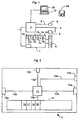
- FIG. 1 shows a schematic block diagram of a system for performing a method according to the invention.
- a vehicle such as a truck and a ship, comprises an internal combustion engine 1 in the form of a diesel engine, here comprising four cylinders 2a-2d.
- the number of cylinders is kept to four for illustration purposes only. It must be understood that the invention is applicable to any multicylinder combustion engine with any known number of cylinders.
- the embodiment described here relates to a combustion engine arranged in a vehicle, a person skilled in the art appreciates that the invention also is applicable to combustion engines not arranged in a vehicle; the combustion engine may for example be installed in a power plant.
- the combustion engine 1 is controlled by an electronic engine control unit 3 embedded in the vehicle.
- the engine control unit 3 is adapted to receive sensed engine data in the form of e.g. a toothed flywheel signal (TF-signal) and a gear signal.
- the TF-signal is received on a first line 4 from an engine-speed sensor 5 which senses rotation of the engine's toothed flywheel 6.
- the engine-speed sensor 5 may be e.g. an inductive type sensor or a hall-effect sensor. Of course there may be more than one engine-speed sensor 5 and other positions for measuring the engine speed, such as measuring the rotation the combustion engine's 1 crankshaft (not shown).
- the engine control unit 3 is also adapted to send control signals through a set of second lines 7a-7d to a fuel injector unit (not shown) respectively, for the supply of fuel to each cylinder 2a-2d.
- the gear signal is a discrete signal received on a third line 8 from e.g. a discrete transmission sensor 9, which typically provides the gear signal when the transmission is in neutral. All this is known to a person skilled in the art and is therefore not described more in detail.
- the engine control unit 3 is connected to a vehicle external computer 10, for example an external PC laptop, through which the method according to the invention is initiated.
- a vehicle external computer 10 for example an external PC laptop
- the external computer 10 may of course be indirectly connected to the engine control unit 3 via one or more other embedded or external electronic control units, gateways and interfaces.
- the communication between the external computer 10 and the engine control unit 3 may of course also be partly or substantially wireless.
- Fig. 2 schematically shows the engine control unit 3, which comprises a first CPU 11 connected to a first port 12a via a first bus 13a in order to receive the TF-signal from the engine-speed sensor 5, a second port 12b via a second bus 13b for receiving the gear signal from the transmission sensor 9, a third port 12c via a third bus 13c for communication with the injector units and a fourth port 12d via a fourth bus 13d for communication with the external computer 10.
- the first CPU 11 is also connected to at least one storing means 14, such as a hard disk, a flash memory and a ROM (Read-only memory), via a fifth bus 13e.
- the engine control unit 3 suitably also comprises other components commonly used in an ECU (Electronic Control Unit) for vehicles, e.g.
- a Random-Access memory an EEPROM, a Bus Controller and A/D-converters (not shown) in the case where e.g. both the gear signal and TF-signal are analogue signals.
- Installed in the storing means 14 are e.g. an engine speed sensor interface computer program 15 for interpreting the TF-signal, a transmission sensor interface computer program 16 for interpreting the gear signal, a fuel control computer program 17 for controlling the supply of fuel to the cylinders 2a-d and a first communication interface computer program 18 for communication with the external computer 10.
- These computer programs 15-18 may be program modules in an engine control computer program. It must also be understood that several functions may be implemented as partly software and hardware as known to a person skilled in the art.
- Fig. 3 schematically shows an example of the external computer 10, which comprises a second CPU 19 connected to a fifth port 12e via a sixth bus 13f for communication with the engine control unit 3and a sixth port 12fvia a seventh bus 13g for communication with a display, which may show a graphical or character-based user interface.
- the second CPU 19 is also connected to at least one second storing means 20, such as a hard disk, a flash memory and a ROM via an eighth bus 13h.
- the second storing means 20 comprises a cylinder test computer program, which suitably comprises a second communication interface program module 21 for communication with the engine control unit 3, a user interface program module 22 and a criteria checking program module 23.
- the cylinder test computer program may be downloaded to the external computer, e.g.
- a computer program product 24 such as a floppy disk (see Fig. 1), an external hard disk, a CD, a DVD and a flash memory, and through a server via a Local Area Network or Wide Area Network.
- a computer program product 24 such as a floppy disk (see Fig. 1), an external hard disk, a CD, a DVD and a flash memory, and through a server via a Local Area Network or Wide Area Network.
- a computer program product 24 such as a floppy disk (see Fig. 1), an external hard disk, a CD, a DVD and a flash memory, and through a server via a Local Area Network or Wide Area Network.
- a person starts the cylinder test computer program on the external computer 10, which causes a display 25 (see Fig. 1) connected to the external computer 10 to show e.g. a GUI (graphical user interface).
- a second step S2 the person requests a start of the cylinder test by e.g. pushing a start button in the GUI.
- the request is sent to the engine control unit 3, which in a third step S3 checks whether all of at least one criterion for starting the cylinder test is fulfilled.
- the criterion may be that the gear signal is received from the transmission sensor 9, i.e. that the gearbox is in the neutral position.
- Another criterion may be that the parking brake (not shown) of the vehicle is activated. Yet another criterion is that the sensed vehicle speed is zero or below a certain value. Still another criterion may be that a pedal position sensor (not shown) indicates that e.g. the clutch pedal is unaffected. If the at least one criterion is not fulfilled, the request to start the testing will be denied and step S2 has to be carried out again. When the at least one criterion is fulfilled the cylinder test is started and the method continues with a fourth step S4 in which the cylinder test computer program causes the external computer 10 to instruct the engine control unit 3 to start the combustion engine 1. When the combustion engine 1 has been started and is running at a relatively low speed L0, e.g.
- a fifth step S5 starts, in which the cylinder test computer program causes an acceleration of the combustion engine up to a first engine speed L1. All the cylinders 2a-2d could throughout this acceleration be supplied with an equal amount of fuel.
- the first engine speed L1 preferably corresponds to a speed level above typical propulsion conditions of the vehicle.
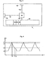
- the fuel supply to all cylinders except the cylinder to be tested is interrupted. This is done in a sixth step S6, which correspond to the time to in Fig 4.
- the fuel supply to only the tested cylinder is not enough to keep the first engine speed L1, since the braking effect caused by e.g. internal compression strokes in the other cylinders is more powerful than the power output from the tested cylinder when the engine is running at the first engine speed L1.
- step S6 causes the speed of the engine to decrease.
- the fuel supply to the tested cylinder may even be increased without overcoming the braking effect.
- the fuel injection for each cylinder up to L1 may be kept relatively low compared to the fuel injection for the tested cylinder after the fuel interruption to the other cylinders.
- the engine control unit 3 and/or the external computer 10 starts to count the time, while monitoring of the speed of the engine continues. This is performed in a seventh step S7.
- the counting starts when the speed of the engine has decreased to a second engine speed L2 after the interruption, which second speed L2 in this embodiment only is slightly lower than the first engine speed L1.
- the start of the counting in the alternative seventh step corresponds to time t 1 in Fig. 4, in which t 1 is soon after the interruption of the fuel supply in order to still be able to test an individual cylinder working at a relatively high engine speed.
- the stopping is executed in an eighth step S8, which corresponds to time t 2 in Fig. 4.
- the time between t 0 and t 2 , or in the alternative step S7, t 1 and t 2 is then used for, e.g., a direct comparison with a deceleration time for a healthy cylinder.
- the deceleration time for the healthy cylinder may for instance be stored in a database in the external computer 10, suitably as a part of the cylinder test computer program. If the measured time between t 0 and t 2 and t 1 and t 2 respectively, deviates more from the deceleration time for the healthy cylinder than to a predetermined extent, a conclusion can be drawn that there is a fault associated with the tested cylinder.
- a ninth step S9 in this embodiment an equal amount of fuel is supplied again to all the cylinders after the third engine speed has been reached and the counting has stopped.
- the start of the fuel supply corresponds to the time t 3 in Fig. 4. However, this time the fuel supply is much lower than during the acceleration in step S5, and the speed of the engine continues to decrease, but in a more controlled way, down to the low speed L0, where, if needed, more fuel is supplied in order to keep the low speed L0 when reached.
- the low speed L0 is controlled during a tenth step S10.
- the fuel supply to the tested cylinder is interrupted after the counting has stopped.
- the interruption in the alternative step S9 may be performed with the help of the ordinary engine control computer program, which may order the engine to return to idle speed.
- Typical modern engine control computer programs causes an immediate interruption of the fuel supply if a current speed is higher than a requested speed.
- the alternative step S9 saves fuel and causes a faster return to the low speed L0. Fuel is again supplied to all the cylinders 2a-2d first when the speed of the engine has reached down to or is close to the low speed L0 in order to maintain the low speed L0 before the steps S5-S10 are repeated.
- the steps S5-S10 may be repeated several times for testing one of the cylinders several times in order to get a mean time value which statistically is more accurate than a single performance of the steps S5-S10.
- the steps S5-S10 may also be repeated for all the cylinders, i.e. another cylinder may be tested in a subsequent repetition of step S5-S10 directly following a previous performance of step S5-S10 in which another cylinder was tested.
- the checking of the at least one criterion suitably continues as long as one of the steps S4-S10 is performed. If, for example, the gear signal ceases from the transmission sensor 9, the testing and the fuel supply to the combustion engine 1 are immediately interrupted.
Landscapes
- Chemical & Material Sciences (AREA)
- Engineering & Computer Science (AREA)
- Combustion & Propulsion (AREA)
- Physics & Mathematics (AREA)
- General Physics & Mathematics (AREA)
- Combined Controls Of Internal Combustion Engines (AREA)
- Testing Of Engines (AREA)
- Control Of Electric Motors In General (AREA)
- Debugging And Monitoring (AREA)
Claims (12)
- Verfahren zum Identifizieren einer einem einzelnen Zylinder eines Mehr-Zylinder-Verbrennungsmotors (1) zugeordneten Fehlfunktion, umfassend die Schritte:Beschleunigen des Verbrennungsmotors (1) auf eine erste Motordrehzahl (L1); Unterbrechen der Kraftstoffzufuhr zu allen Zylindern mit Ausnahme des einzelnen Zylinders, der eine vorbestimmte Kraftstoffzufuhrmengen erhält, wenn die erste Motordrehzahl (L1) erreicht ist; undErfassen der Zeit, die erforderlich ist, damit die Drehzahl des Verbrennungsmotors (1) entweder von der ersten Motordrehzahl (L1) oder von einer zweiten Motordrehzahl (L2), die niedriger als die erste Motordrehzahl (L1) ist, auf eine dritte Motordrehzahl (L3) abfällt.
- Verfahren nach Anspruch 1, umfassend den Schritt des Zuführens einer im Wesentlichen gleichen ersten Menge an Kraftstoff zu allen Zylindern (2a-2d) während des Schritts des Beschleunigens des Verbrennungsmotors (1).
- Verfahren nach Anspruch 1 oder 2, das nach Erreichen der dritten Motordrehzahl (L3) den Schritt des Unterbrechens der Kraftstoffzufuhr zu dem einzelnen Zylinder umfasst.
- Verfahren nach einem der Ansprüche 1 bis 3, umfassend den Schritt des Aufrechterhaltens der Drehzahl des Verbrennungsmotors (1) auf einer im Wesentlichen konstanten niedrigen Drehzahl (L0), die niedriger ist, als die dritte Motordrehzahl (L3), bevor das Verfahren zum erneuten Testen des einzelnen Zylinders oder eines anderen der Zylinder (2a-2d) des Verbrennungsmotors (1) wiederholt wird.
- Verfahren nach einem der vorangehenden Ansprüche, umfassend den Schritt des Vergleichens der erfassten Zeit mit einer vorbestimmten Zeit, die die Verzögerungszeit für einen korrekt funktionierenden Zylinder wiedergibt.
- Verfahren nach einem der vorangehenden Ansprüche, wobei der Verbrennungsmotor (1) ein Dieselmotor in einem Fahrzeug ist.
- Computerprogramm zum Identifizieren einer einem einzelnen Zylinder eines Mehr-Zylinder-Verbrennungsmotors (1) zugeordneten Fehlfunktion, umfassend von einem Computer lesbare Programmcodemittel, um zu veranlassen, dass eine Motorsteuereinheit (3) eine Beschleunigung des Verbrennungsmotors (1) auf eine erste Motordrehzahl (L1) bewirkt;von einem Computer lesbare Programmcodemittel, um zu veranlassen, dass die Motorsteuereinheit (3) die Kraftstoffzufuhr zu allen Zylindern unterbricht, mit Ausnahme des einzelnen Zylinders, der eine vorbestimmte Kraftstoffzufuhrmengen erhält, wenn die erste Motordrehzahl (L1) erreicht wird; undvon einem Computer lesbare Programmcodemittel, um zu veranlassen, dass entweder die Motorsteuereinheit (3) oder ein weiterer Computer (10), der mit der Motorsteuereinheit (3) verbunden ist, die Zeit erfasst, die erforderlich ist, damit die Drehzahl des Verbrennungsmotors (1) entweder von der ersten Motordrehzahl (L1) oder von einer zweiten Motordrehzahl (L2), die niedriger ist als die erste Motordrehzahl (L1), auf eine dritte Motordrehzahl (L3) abfällt.
- Computerprogramm nach Anspruch 7, umfassend von einem Computer lesbare Programmcodemittel, um zu veranlassen, dass die Motorsteuereinheit (3) oder ein weiterer mit der Motorsteuereinheit (3) verbundener Computer (10) eine graphische Benutzeroberfläche auf einer Anzeigeeinrichtung (25) anzeigt.
- Computerprogramm nach Anspruch 7 oder 8, umfassend von einem Computer lesbare Programmcodemittel, um zu veranlassen, dass die Motorsteuereinheit (3) oder ein weiterer mit der Motorsteuereinheit (3) verbundener Computer überprüft, ob alle Kriterien von wenigstens einem Kriterium zum Überprüfen des einzelnen Zylinders erfüllt sind.
- Computerprogramm nach einem der Ansprüche 7 bis 9, umfassend von einem Computer lesbare Programmcodemittel, um zu veranlassen, dass die Motorsteuereinheit (3) oder ein weiterer mit der Motorsteuereinheit (3) verbundener Computer eine gespeicherte vorbestimmte Zeit mit der Zeit vergleicht, die benötigt wird, damit die Drehzahl des Verbrennungsmotors (1) entweder von der ersten Motordrehzahl (L1) oder von der zweiten Motordrehzahl (L2) auf die dritte Motordrehzahl (L3) abfällt.
- Computerprogrammprodukt (24) umfassend ein Computerprogramm nach Anspruch 7 und ein von einem Computer lesbares Medium, auf dem das Computerprogramm gespeichert ist.
- Computer, wie beispielsweise eine integrierte elektronische Motorsteuereinheit (3) oder ein fahrzeugexterner Computer (10), umfassend ein Speichermittel (14, 20) und ein Computerprogramm nach Anspruch 7, das in dem Speichermittel (14, 20) gespeichert ist.
Applications Claiming Priority (3)
| Application Number | Priority Date | Filing Date | Title |
|---|---|---|---|
| SE0202005 | 2002-06-28 | ||
| SE0202005A SE522658C2 (sv) | 2002-06-28 | 2002-06-28 | Metod för att identifiera ett fel förknippat med en särskild cylinder i en flercylindrig förbränningsmotor och datorprogram för genomförande av metoden |
| PCT/SE2003/000602 WO2004003503A1 (en) | 2002-06-28 | 2003-04-15 | A method and computer program for identifying a fault in an engine |
Publications (2)
| Publication Number | Publication Date |
|---|---|
| EP1520163A1 EP1520163A1 (de) | 2005-04-06 |
| EP1520163B1 true EP1520163B1 (de) | 2005-11-30 |
Family
ID=20288356
Family Applications (1)
| Application Number | Title | Priority Date | Filing Date |
|---|---|---|---|
| EP03721198A Expired - Lifetime EP1520163B1 (de) | 2002-06-28 | 2003-04-15 | Verfahren und computerprogramm zum identifizieren eines fehlers in einem motor |
Country Status (9)
| Country | Link |
|---|---|
| US (1) | US7302337B2 (de) |
| EP (1) | EP1520163B1 (de) |
| JP (1) | JP4178146B2 (de) |
| AT (1) | ATE311590T1 (de) |
| AU (1) | AU2003224537A1 (de) |
| DE (1) | DE60302577T2 (de) |
| ES (1) | ES2256732T3 (de) |
| SE (1) | SE522658C2 (de) |
| WO (1) | WO2004003503A1 (de) |
Cited By (2)
| Publication number | Priority date | Publication date | Assignee | Title |
|---|---|---|---|---|
| EP1983326A1 (de) | 2007-04-17 | 2008-10-22 | Scania CV AB (PUBL) | Verfahren zur Erkennung eines defekten Zylinders in einem mehrzylindrigen Verbrennungsmotor |
| RU2445596C2 (ru) * | 2009-10-26 | 2012-03-20 | Государственное образовательное учреждение высшего профессионального образования Военный инженерно-технический университет | Автоматизированная система диагностики стационарных дизельных двигателей |
Families Citing this family (6)
| Publication number | Priority date | Publication date | Assignee | Title |
|---|---|---|---|---|
| US7369932B2 (en) * | 2006-05-04 | 2008-05-06 | Honeywell International, Inc. | System and method for turbine engine fault detection using discrete event system modeling |
| GB0610226D0 (en) * | 2006-05-23 | 2006-07-05 | Delphi Tech Inc | Drive circuit for an injector arrangement and a diagnostic method |
| ATE505636T1 (de) * | 2006-05-30 | 2011-04-15 | Delphi Technologies Holding | Regler und regelverfahren für ein motorsteuergerät |
| JP4836095B2 (ja) * | 2008-07-30 | 2011-12-14 | トヨタ自動車株式会社 | 省燃費運転診断装置、車載システムおよび省燃費運転診断プログラム |
| SE537277C2 (sv) * | 2013-07-03 | 2015-03-24 | Scania Cv Ab | Förfarande och system för analys av insprutningsorgan |
| CN114233552A (zh) * | 2021-12-21 | 2022-03-25 | 潍柴动力股份有限公司 | 火花塞失效的确定方法、装置、存储介质和电子设备 |
Family Cites Families (12)
| Publication number | Priority date | Publication date | Assignee | Title |
|---|---|---|---|---|
| US3972230A (en) * | 1975-06-19 | 1976-08-03 | Rca Corporation | Detecting malfunction in cylinders of internal combustion engines |
| DE3105331C2 (de) * | 1981-02-13 | 1986-10-23 | Siemens AG, 1000 Berlin und 8000 München | Verfahren zum Vergleich von an einer leer laufenden Dieselmaschine gemessenen Maschinenzykluszeiten |
| JPS60166734A (ja) * | 1984-02-09 | 1985-08-30 | Honda Motor Co Ltd | 多気筒内燃エンジンの燃料供給制御方法 |
| US4941445A (en) * | 1988-05-16 | 1990-07-17 | Motorola, Inc. | Electronic position sensor assembly and engine control system |
| DE4002210C2 (de) | 1990-01-26 | 1999-10-14 | Bosch Gmbh Robert | Verfahren zum Trennen eines Motorzylinders mit Verbrennungsaussetzern von der Kraftstoffzufuhr |
| JP2943045B2 (ja) * | 1994-04-22 | 1999-08-30 | 株式会社ユニシアジェックス | 多気筒内燃機関の失火診断装置 |
| EP0763725A3 (de) * | 1995-09-14 | 1999-07-21 | MTU Motoren- und Turbinen-Union Friedrichshafen GmbH | Verfahren zur Bestimmung der Unterschiede ungleichförmiger Zylindermomente bei einer Brennkraftmaschine und Anwendung des Verfahrens |
| DE19540826C2 (de) * | 1995-11-02 | 1998-01-22 | Daimler Benz Ag | Verfahren zur zylinderindividuellen Fehlfunktionserkennung bei einer Brennkraftmaschine |
| DE19813495C1 (de) | 1998-03-26 | 1999-07-08 | Scania Cv Ab | Verfahren zum Erkennen einer fehlerhaft funktionierenden Kolben/Zylinder-Einheit eines Mehrzylinderverbrennungsmotors |
| US5979407A (en) * | 1998-06-01 | 1999-11-09 | Cummins Engine Company, Inc. | Passive and active misfire diagnosis for internal combustion engines |
| JP2002106390A (ja) * | 2000-09-29 | 2002-04-10 | Fuji Heavy Ind Ltd | 多気筒エンジンの制御装置 |
| DE10055192C2 (de) * | 2000-11-07 | 2002-11-21 | Mtu Friedrichshafen Gmbh | Rundlaufregelung für Dieselmotoren |
-
2002
- 2002-06-28 SE SE0202005A patent/SE522658C2/sv not_active IP Right Cessation
-
2003
- 2003-04-15 WO PCT/SE2003/000602 patent/WO2004003503A1/en not_active Ceased
- 2003-04-15 DE DE60302577T patent/DE60302577T2/de not_active Expired - Lifetime
- 2003-04-15 JP JP2004517434A patent/JP4178146B2/ja not_active Expired - Fee Related
- 2003-04-15 AU AU2003224537A patent/AU2003224537A1/en not_active Abandoned
- 2003-04-15 ES ES03721198T patent/ES2256732T3/es not_active Expired - Lifetime
- 2003-04-15 EP EP03721198A patent/EP1520163B1/de not_active Expired - Lifetime
- 2003-04-15 AT AT03721198T patent/ATE311590T1/de not_active IP Right Cessation
- 2003-04-15 US US10/521,419 patent/US7302337B2/en not_active Expired - Lifetime
Cited By (2)
| Publication number | Priority date | Publication date | Assignee | Title |
|---|---|---|---|---|
| EP1983326A1 (de) | 2007-04-17 | 2008-10-22 | Scania CV AB (PUBL) | Verfahren zur Erkennung eines defekten Zylinders in einem mehrzylindrigen Verbrennungsmotor |
| RU2445596C2 (ru) * | 2009-10-26 | 2012-03-20 | Государственное образовательное учреждение высшего профессионального образования Военный инженерно-технический университет | Автоматизированная система диагностики стационарных дизельных двигателей |
Also Published As
| Publication number | Publication date |
|---|---|
| WO2004003503A1 (en) | 2004-01-08 |
| DE60302577D1 (de) | 2006-01-05 |
| EP1520163A1 (de) | 2005-04-06 |
| US20050119818A1 (en) | 2005-06-02 |
| SE522658C2 (sv) | 2004-02-24 |
| SE0202005D0 (sv) | 2002-06-28 |
| ES2256732T3 (es) | 2006-07-16 |
| SE0202005L (sv) | 2003-12-29 |
| JP4178146B2 (ja) | 2008-11-12 |
| ATE311590T1 (de) | 2005-12-15 |
| AU2003224537A1 (en) | 2004-01-19 |
| DE60302577T2 (de) | 2006-08-03 |
| JP2005531721A (ja) | 2005-10-20 |
| US7302337B2 (en) | 2007-11-27 |
Similar Documents
| Publication | Publication Date | Title |
|---|---|---|
| US9863356B2 (en) | Fuel rail pressure sensor diagnostic techniques | |
| US4366794A (en) | Fuel injection control method for internal combustion engines | |
| US20030144778A1 (en) | Vehicle electronic control system having fail-safe function | |
| US5987888A (en) | System and method for controlling a turbocharger | |
| JP2002532646A (ja) | クランクケース圧力に基づくエンジン動作不良検出のためのシステム及び方法 | |
| EP1520163B1 (de) | Verfahren und computerprogramm zum identifizieren eines fehlers in einem motor | |
| US6216668B1 (en) | Engine performance measuring method | |
| US6002980A (en) | System and method for engine cylinder power diagnosis by cylinder(s) cut-off snap throttle engine acceleration tests | |
| US6368248B1 (en) | Method and device for controlling a drive unit of a vehicle | |
| US20140366835A1 (en) | Avoidance of a safety fuel cut-off during partial engine operation | |
| US11118527B2 (en) | Internal combustion engine control system | |
| CN118346451A (zh) | 一种发动机控制方法、装置、车辆和可读存储介质 | |
| JPH06239166A (ja) | 車両の故障表示方法および装置 | |
| US8433464B2 (en) | Method for simplifying torque distribution in multiple drive systems | |
| US7280907B2 (en) | Method of enhancing accelerator pedal safety interlock feature | |
| JPH11148406A (ja) | エンジンのスロットル弁制御装置 | |
| KR102133487B1 (ko) | 비정상 연소 중에 내연 기관을 제어하기 위한 방법 | |
| CN107351684B (zh) | 车辆的控制装置 | |
| JP3262419B2 (ja) | エンジンの点火装置 | |
| JP2000073840A (ja) | 車両用内燃機関の燃料噴射制御装置 | |
| KR100273891B1 (ko) | 크랭크 포지션 센서의 고장시 시동꺼짐 방지방법 | |
| JPS6371534A (ja) | 内燃機関制御装置 | |
| JP2625018B2 (ja) | 電子制御エンジン制御方法 | |
| CN116641793A (zh) | 一种发动机的异常检测方法、装置、车辆和存储介质 | |
| JP2025016143A (ja) | 電子制御装置、電子制御装置の制御方法 |
Legal Events
| Date | Code | Title | Description |
|---|---|---|---|
| PUAI | Public reference made under article 153(3) epc to a published international application that has entered the european phase |
Free format text: ORIGINAL CODE: 0009012 |
|
| 17P | Request for examination filed |
Effective date: 20050128 |
|
| AK | Designated contracting states |
Kind code of ref document: A1 Designated state(s): AT BE BG CH CY CZ DE DK EE ES FI FR GB GR HU IE IT LI LU MC NL PT RO SE SI SK TR |
|
| AX | Request for extension of the european patent |
Extension state: AL LT LV MK |
|
| GRAP | Despatch of communication of intention to grant a patent |
Free format text: ORIGINAL CODE: EPIDOSNIGR1 |
|
| GRAS | Grant fee paid |
Free format text: ORIGINAL CODE: EPIDOSNIGR3 |
|
| GRAA | (expected) grant |
Free format text: ORIGINAL CODE: 0009210 |
|
| AK | Designated contracting states |
Kind code of ref document: B1 Designated state(s): AT BE BG CH CY CZ DE DK EE ES FI FR GB GR HU IE IT LI LU MC NL PT RO SE SI SK TR |
|
| PG25 | Lapsed in a contracting state [announced via postgrant information from national office to epo] |
Ref country code: CZ Free format text: LAPSE BECAUSE OF FAILURE TO SUBMIT A TRANSLATION OF THE DESCRIPTION OR TO PAY THE FEE WITHIN THE PRESCRIBED TIME-LIMIT Effective date: 20051130 Ref country code: CH Free format text: LAPSE BECAUSE OF FAILURE TO SUBMIT A TRANSLATION OF THE DESCRIPTION OR TO PAY THE FEE WITHIN THE PRESCRIBED TIME-LIMIT Effective date: 20051130 Ref country code: FI Free format text: LAPSE BECAUSE OF FAILURE TO SUBMIT A TRANSLATION OF THE DESCRIPTION OR TO PAY THE FEE WITHIN THE PRESCRIBED TIME-LIMIT Effective date: 20051130 Ref country code: NL Free format text: LAPSE BECAUSE OF FAILURE TO SUBMIT A TRANSLATION OF THE DESCRIPTION OR TO PAY THE FEE WITHIN THE PRESCRIBED TIME-LIMIT Effective date: 20051130 Ref country code: AT Free format text: LAPSE BECAUSE OF FAILURE TO SUBMIT A TRANSLATION OF THE DESCRIPTION OR TO PAY THE FEE WITHIN THE PRESCRIBED TIME-LIMIT Effective date: 20051130 Ref country code: SI Free format text: LAPSE BECAUSE OF FAILURE TO SUBMIT A TRANSLATION OF THE DESCRIPTION OR TO PAY THE FEE WITHIN THE PRESCRIBED TIME-LIMIT Effective date: 20051130 Ref country code: LI Free format text: LAPSE BECAUSE OF FAILURE TO SUBMIT A TRANSLATION OF THE DESCRIPTION OR TO PAY THE FEE WITHIN THE PRESCRIBED TIME-LIMIT Effective date: 20051130 Ref country code: BE Free format text: LAPSE BECAUSE OF FAILURE TO SUBMIT A TRANSLATION OF THE DESCRIPTION OR TO PAY THE FEE WITHIN THE PRESCRIBED TIME-LIMIT Effective date: 20051130 Ref country code: SK Free format text: LAPSE BECAUSE OF FAILURE TO SUBMIT A TRANSLATION OF THE DESCRIPTION OR TO PAY THE FEE WITHIN THE PRESCRIBED TIME-LIMIT Effective date: 20051130 Ref country code: RO Free format text: LAPSE BECAUSE OF FAILURE TO SUBMIT A TRANSLATION OF THE DESCRIPTION OR TO PAY THE FEE WITHIN THE PRESCRIBED TIME-LIMIT Effective date: 20051130 |
|
| REG | Reference to a national code |
Ref country code: CH Ref legal event code: EP Ref country code: GB Ref legal event code: FG4D |
|
| REG | Reference to a national code |
Ref country code: IE Ref legal event code: FG4D |
|
| REF | Corresponds to: |
Ref document number: 60302577 Country of ref document: DE Date of ref document: 20060105 Kind code of ref document: P |
|
| REG | Reference to a national code |
Ref country code: DE Ref legal event code: R096 Ref document number: 60302577 Country of ref document: DE Effective date: 20060105 |
|
| PG25 | Lapsed in a contracting state [announced via postgrant information from national office to epo] |
Ref country code: DK Free format text: LAPSE BECAUSE OF FAILURE TO SUBMIT A TRANSLATION OF THE DESCRIPTION OR TO PAY THE FEE WITHIN THE PRESCRIBED TIME-LIMIT Effective date: 20060228 Ref country code: SE Free format text: LAPSE BECAUSE OF FAILURE TO SUBMIT A TRANSLATION OF THE DESCRIPTION OR TO PAY THE FEE WITHIN THE PRESCRIBED TIME-LIMIT Effective date: 20060228 Ref country code: GR Free format text: LAPSE BECAUSE OF FAILURE TO SUBMIT A TRANSLATION OF THE DESCRIPTION OR TO PAY THE FEE WITHIN THE PRESCRIBED TIME-LIMIT Effective date: 20060228 Ref country code: BG Free format text: LAPSE BECAUSE OF FAILURE TO SUBMIT A TRANSLATION OF THE DESCRIPTION OR TO PAY THE FEE WITHIN THE PRESCRIBED TIME-LIMIT Effective date: 20060228 |
|
| PG25 | Lapsed in a contracting state [announced via postgrant information from national office to epo] |
Ref country code: IE Free format text: LAPSE BECAUSE OF NON-PAYMENT OF DUE FEES Effective date: 20060417 |
|
| PG25 | Lapsed in a contracting state [announced via postgrant information from national office to epo] |
Ref country code: MC Free format text: LAPSE BECAUSE OF NON-PAYMENT OF DUE FEES Effective date: 20060430 |
|
| PG25 | Lapsed in a contracting state [announced via postgrant information from national office to epo] |
Ref country code: PT Free format text: LAPSE BECAUSE OF FAILURE TO SUBMIT A TRANSLATION OF THE DESCRIPTION OR TO PAY THE FEE WITHIN THE PRESCRIBED TIME-LIMIT Effective date: 20060502 |
|
| NLV1 | Nl: lapsed or annulled due to failure to fulfill the requirements of art. 29p and 29m of the patents act | ||
| PG25 | Lapsed in a contracting state [announced via postgrant information from national office to epo] |
Ref country code: HU Free format text: LAPSE BECAUSE OF FAILURE TO SUBMIT A TRANSLATION OF THE DESCRIPTION OR TO PAY THE FEE WITHIN THE PRESCRIBED TIME-LIMIT Effective date: 20060601 |
|
| REG | Reference to a national code |
Ref country code: CH Ref legal event code: PL |
|
| REG | Reference to a national code |
Ref country code: ES Ref legal event code: FG2A Ref document number: 2256732 Country of ref document: ES Kind code of ref document: T3 |
|
| ET | Fr: translation filed | ||
| PLBE | No opposition filed within time limit |
Free format text: ORIGINAL CODE: 0009261 |
|
| STAA | Information on the status of an ep patent application or granted ep patent |
Free format text: STATUS: NO OPPOSITION FILED WITHIN TIME LIMIT |
|
| 26N | No opposition filed |
Effective date: 20060831 |
|
| REG | Reference to a national code |
Ref country code: DE Ref legal event code: R097 Ref document number: 60302577 Country of ref document: DE Effective date: 20060831 |
|
| REG | Reference to a national code |
Ref country code: IE Ref legal event code: MM4A |
|
| PG25 | Lapsed in a contracting state [announced via postgrant information from national office to epo] |
Ref country code: EE Free format text: LAPSE BECAUSE OF FAILURE TO SUBMIT A TRANSLATION OF THE DESCRIPTION OR TO PAY THE FEE WITHIN THE PRESCRIBED TIME-LIMIT Effective date: 20051130 |
|
| PG25 | Lapsed in a contracting state [announced via postgrant information from national office to epo] |
Ref country code: LU Free format text: LAPSE BECAUSE OF NON-PAYMENT OF DUE FEES Effective date: 20060415 Ref country code: TR Free format text: LAPSE BECAUSE OF FAILURE TO SUBMIT A TRANSLATION OF THE DESCRIPTION OR TO PAY THE FEE WITHIN THE PRESCRIBED TIME-LIMIT Effective date: 20051130 |
|
| PG25 | Lapsed in a contracting state [announced via postgrant information from national office to epo] |
Ref country code: CY Free format text: LAPSE BECAUSE OF FAILURE TO SUBMIT A TRANSLATION OF THE DESCRIPTION OR TO PAY THE FEE WITHIN THE PRESCRIBED TIME-LIMIT Effective date: 20051130 |
|
| PGFP | Annual fee paid to national office [announced via postgrant information from national office to epo] |
Ref country code: ES Payment date: 20090508 Year of fee payment: 7 |
|
| PGFP | Annual fee paid to national office [announced via postgrant information from national office to epo] |
Ref country code: FR Payment date: 20090417 Year of fee payment: 7 Ref country code: IT Payment date: 20090427 Year of fee payment: 7 |
|
| PGFP | Annual fee paid to national office [announced via postgrant information from national office to epo] |
Ref country code: GB Payment date: 20090415 Year of fee payment: 7 |
|
| GBPC | Gb: european patent ceased through non-payment of renewal fee |
Effective date: 20100415 |
|
| REG | Reference to a national code |
Ref country code: FR Ref legal event code: ST Effective date: 20101230 |
|
| PG25 | Lapsed in a contracting state [announced via postgrant information from national office to epo] |
Ref country code: IT Free format text: LAPSE BECAUSE OF NON-PAYMENT OF DUE FEES Effective date: 20100415 Ref country code: GB Free format text: LAPSE BECAUSE OF NON-PAYMENT OF DUE FEES Effective date: 20100415 |
|
| REG | Reference to a national code |
Ref country code: ES Ref legal event code: FD2A Effective date: 20110711 |
|
| PG25 | Lapsed in a contracting state [announced via postgrant information from national office to epo] |
Ref country code: ES Free format text: LAPSE BECAUSE OF NON-PAYMENT OF DUE FEES Effective date: 20110629 |
|
| PG25 | Lapsed in a contracting state [announced via postgrant information from national office to epo] |
Ref country code: ES Free format text: LAPSE BECAUSE OF NON-PAYMENT OF DUE FEES Effective date: 20100416 |
|
| PG25 | Lapsed in a contracting state [announced via postgrant information from national office to epo] |
Ref country code: FR Free format text: LAPSE BECAUSE OF NON-PAYMENT OF DUE FEES Effective date: 20100430 |
|
| PGFP | Annual fee paid to national office [announced via postgrant information from national office to epo] |
Ref country code: DE Payment date: 20220302 Year of fee payment: 20 |
|
| REG | Reference to a national code |
Ref country code: DE Ref legal event code: R071 Ref document number: 60302577 Country of ref document: DE |
|
| P01 | Opt-out of the competence of the unified patent court (upc) registered |
Effective date: 20230518 |