EP1519212A1 - Dispositif d'affichage permettant la commutation irreversible d'un premier état vers un deuxiéme état - Google Patents
Dispositif d'affichage permettant la commutation irreversible d'un premier état vers un deuxiéme état Download PDFInfo
- Publication number
- EP1519212A1 EP1519212A1 EP03021893A EP03021893A EP1519212A1 EP 1519212 A1 EP1519212 A1 EP 1519212A1 EP 03021893 A EP03021893 A EP 03021893A EP 03021893 A EP03021893 A EP 03021893A EP 1519212 A1 EP1519212 A1 EP 1519212A1
- Authority
- EP
- European Patent Office
- Prior art keywords
- chamber
- display device
- liquid
- exit opening
- receiving space
- Prior art date
- Legal status (The legal status is an assumption and is not a legal conclusion. Google has not performed a legal analysis and makes no representation as to the accuracy of the status listed.)
- Withdrawn
Links
Images

Classifications
-
- G—PHYSICS
- G02—OPTICS
- G02B—OPTICAL ELEMENTS, SYSTEMS OR APPARATUS
- G02B26/00—Optical devices or arrangements for the control of light using movable or deformable optical elements
- G02B26/004—Optical devices or arrangements for the control of light using movable or deformable optical elements based on a displacement or a deformation of a fluid
Definitions
- the present invention relates to a non-reversible display device capable of irreversibly switching from a first indicating state to a second indicating state.
- indicating or displaying devices of different types and technologies are known in the prior art.
- electrochrome display devices see e.g. DE-A-25 45 391 and DE-A-198 25 371
- electroluminescent display devices see e.g. DE-A-100 42 500
- the widely spread LCD display devices e.g. indicating devices are known in which the change of an indicating state results from a chemically induced change of colour (see e.g. EP-B-0 081 031 and DE-A-44 43 470).
- the problem with all of the above-identified types of display devices is that maintaining one of the two indicating states requires the provision of energy of a power supply. As soon as power is no longer supplied (e.g. due to an exhaust of the power supply like a battery or the like) the display device automatically switches to the indicating state which requires no power.
- an electrolytic display cell comprising two parallel plates whereof one is covered by a semi-transparent electrode and whereof the other supports a counter-electrode. Between the electrode and the counter-electrode an electrolyte is arranged containing a metallic salt dissolved in a solvent. The electrode and counter-electrode are connected to the positive and negative terminals of a d.c. voltage source via a switch permitting the connection of each terminal to any one of the electrodes. Connecting the electrode of the electrolytic display device to the negative terminal of the d.c.
- the voltage source results in a electrolytic deposition of the metallic salt of the electrolyte on the semi-transparent electrode resulting in a change of its transmissivity defining a first indicating state. If the electrode is connected to the positive terminal of the d.c. voltage source, the metallic salt disposed on the semi-transparent electrode dissolves into the electrolyte. That means an indication on the known electrolytic display device can be erased again which is a disadvantage if the switch can be operated inadvertently so that valuable information may get lost.
- Another object of the present invention is to provide a non-reversible bistable display device which can be manufactured with low production costs.
- a non-reversible bistable display device capable of irreversibly switching from a first indicating state to a second indicating state, wherein the display device comprises
- the function of the display device according to the invention is based on the discharge of liquid through at least one exit opening of a chamber by increasing the pressure within the chamber to exceed a threshold value.
- a specific feature of the invention is that the increase of pressure results from the generation of gaseous components caused by an electrolysis performed within the chamber and initiated upon the application of electrical energy.
- the chamber comprises an electrolytic liquid and at least two electrodes subjectable to electric voltage.
- the electrolytic liquid comprises conductivity modulators such as for example a salt or other materials basically known to the those skilled in the art.
- the electrolytic liquid can be ink having a sufficient electrical conductivity so as to function as a electrolyte.
- An advantage of the display device according to the invention is the comparatively low energy consumption for activating the display device i.e. for discharging liquid out of the chamber thereby irreversibly switching from a first indicating state in which no liquid is discharged, to a second indicating state in which liquid is or has been discharged.
- Generating the gaseous components using an electrolysis process can already be initiated by the application of relatively low electrical voltage (e.g. in the range of up to about 5 V) and, accordingly, the electrical energy required is rather low.
- relatively low electrical voltage e.g. in the range of up to about 5 V
- the electrolysis can take place over a time of several seconds which further reduces the electrical power required.
- the design of the display device according to the invention need not be complex and, accordingly, its function and operation can be rather reliable also within a wide temperature range because the electrolysis is relatively independent of the temperature of the electrolytic liquid.
- the electrolytic liquid or another indicating liquid can be discharged.
- the chamber is completely filled with electrolytic liquid so that this liquid is discharged out of the at least one exit opening.
- the chamber is partially filled with electrolytic liquid within the area of the two electrodes, but within the area of the at least one exit opening is filled with another indicating liquid. If these two liquids are immisible, the two liquids directly can contact each other.
- a membrane or the like flexible separating film of wall dividing the chamber into two parts wherein in the one part the at least two electrodes and the electrolytic liquid are arranged and in the other part the at least one exit opening and the indicating liquid are located.
- the discharged liquid is received by a receiving space which at least partially is visible from outside.
- the receiving space can be open to the environment so that liquid can exit or the receiving space can be closed.
- a venting opening for exiting gas from the receiving space to the environment when liquid enters the receiving space can be arranged in the receiving space.
- a venting opening is not necessary, because the gas contained in the receiving space can be compressed when the liquid enters the receiving space.
- the receiving space can have an expansion wall so that the receiving space can expand when liquid enters.
- a receiving space can be used employing the mechanisms of venting and/or compression and/or expansion in combination.
- a porous element is arranged within the receiving space for sucking-up the liquid discharged from the at least one exit opening and entering the receiving space.
- the sucking-up of the liquid takes place by capillary forces generated within the porous element.
- the porous element is a fabric and in particular a non-woven fabric.
- each of the exit openings be spaced from each other as far as possible.
- the chamber can be designed like a channel comprising two opposite ends, the one end being provided with the electrodes and the other end being provided with the at least one exit opening.
- a channel can be substantially straight or corrugated or spirally wound.
- the at least one exit opening comprises a means for preventing unintended exit of liquid.
- This means can be a capillary stop i.e. a narrowed area through which the liquid within the chamber will not exit due to surface tension phenomena.
- a capillary stop can be provided by a hydrophobic surface of the chamber within the area of the at least one exit opening. Suitable different designs of capillary stops are known to those skilled in the art of microfluidic systems.
- the chamber of the display device comprises at least one weakened location which will break if the pressure within the chamber exceeds a threshold value.
- the broken weakened location provides an exit opening of the liquid.
- One alternative for providing a weakened location is the formation of a thin portion within the wall of the chamber i.e. a hole in the chamber covered by a film which breaks when the pressure within the chamber exceeds a threshold value.
- the display device 10 comprises a substrate 12 made of a non conductive material such as molded synthetic material, a foil, or glass. Most preferably the substrate 12 comprises an electrically insulating material. Within the substrate 12 there is provided a chamber 14 containing an electrolyte 16. As can be seen from Figures 1 and 3 the chamber 14 is open to the top side 18 of the substrate 12. Within the chamber 14 and preferably at the bottom 20 thereof, there are arranged two electrodes 22,24 connected to a voltage source 26 via a switch 28.
- a porous element 32 provided as a non-woven fabric 34.
- This non-woven fabric comprises synthetic fibers, for example fibres of polypropylene or polyethylene. However, other fibers are also possible. Also other porous elements 32 are possible like for example foamed elements. As described below, the porous element 32 is selected to provide a structure that, by capillary action, is capable of sucking-up liquid from the chamber 14 and distributing it evenly within the recess 30.
- the chamber 14 has a diameter of less than 10mm and the sides of the recess 30 have a length in the range of from about 5 to 12mm.
- the top side 18 of the substrate 12 is covered by a film 36 covering the chamber 14 and the recess 30.
- the film 36 is transparent within its area covering the recess 30 and is opaque within its remaining area and, accordingly, in particular within the area covering the chamber 14. Within its opaque areas the film 36 can be provided with a coating 38.
- the film 36 is mounted to the substrate 12 by means of an adhesive layer 40.
- the film 36 and adhesive layer 40 may, for example, be provided by a conventional transparent adhesive tape applied over the substrate 12.
- the chamber 14 and the recess 30 are separated by a curved narrow edge 42 to which the film 36 is also adhered by the adhesive layer 40. If the pressure within the chamber 14 increases, the film 36 will be subjected to a peeling force around the edge of the recess 30. The peeling force will act preferentially at the edge 42 because of the curvature of the latter and, as soon as it exceeds the adhesive force between the film 36 and the adhesive layer 40 or between the edge 42 and the adhesive layer 40 at this point, the film 36 will peel away from the edge 42.
- Fig. 1 shows the device 10 in its first indicating state in which the chamber 14 completely filled with electrolytic liquid 16 is closed by the film 36.
- Fig. 3 the situation is shown in which the display device 10 is in its second indicating state which will be explained now.
- an operating voltage is applied to the electrodes 22 and 24 by closing the switch 28. Since the electrolytic liquid 16 is electrically conductive, a current is flowing there through. The flow of current through the electrolytic liquid 16 results in an electrolysis which in turn generates gas bubbles 44. The generation of gas of O 2 and H is a normal process in the electrolysis. These gaseous components increases the pressure within the chamber 14. As a result thereof, the force acting on the film 36 at its interface to the edge 42 decreases the adhesive force therebetween so that the film 36 pops up to a little extent providing an exit opening 46 for the chamber 14.
- edge 42 together with the film 36 provides a weakened location 48 which breaks when the pressure in the chamber 14 exceeds a threshold value. Due to the narrow design of the edge 42 the film 36 will release within the area of the edge 42 and not within another area of the top side 18 of the substrate 12. It is possible that several small passages over the edge 42, i.e. several exit openings 46 are provided upon the increase of the pressure within the chamber 14.
- liquid 16 from the chamber 14 exits into the recess 30 which functions as a receiving space 50 for the liquid 16.
- Liquid 16 entering the non-woven fabric 34 will be sucked thereby so that the fabric 34 is filled with the liquid 16.
- the non-woven fabric 34 will change its colour when soaked with the ink, thereby making visible the switching from the first indicating state in which the non-woven fabric 34 has the colour of the fibers thereof, to the second indicating state in which the non-woven fabric 34 is coloured by the ink.
- the embodiment 60 of Fig. 4 is provided with a substrate 12 manufactured in molded interconnect device (MID) technique.
- MID molded interconnect device
- the electrodes 22,24 can be formed as electrically conductive traces along the top surface 18 of the substrate 12 and down into the chamber 14.
- the edge 42 between the chamber 14 and the receiving space 50 (recess 30) at the top side 18 of the substrate 12 is curved towards the chamber 14 resulting in a concentration of the forces for releasing the film 36 from the edge 42.
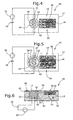
- FIG. 5 an embodiment of a display device 70 is shown in which an annular channel 72 is arranged around the chamber 14 wherein the annular channel 72 is in fluid communication with the receiving space 50.
- the edge 42 between the chamber 14 and the receiving space 50 is annular. Due to the surrounding channel 72 irrespective of where the film 36 will release from the edge 42, liquid 16 from the chamber 14 via the channel 72 will be received by the receiving space 50.
- the substrate 12 of the display device 70 is again made in MID-technique.
- a display device 80 is shown which, adjacent the edge 42, is provided with a channel 82 leading to the receiving space 50.
- the benefit of this design is that through the channel 82 which is dimensioned accordingly, liquid 16 can flow due to capillary forces. This supports the exit of liquid 16 from the chamber 14 even if the film 36 is merely slightly separated from the edge 42.
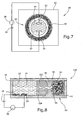
- Fig. 7 shows a design of a device 90 wherein the receiving space 50 is arranged as an annular space surrounding the chamber 14. Also the edge 42 separating the chamber 14 from the receiving space 50 is annular.
- FIG. 8 another design of a display device 100 is shown.
- the chamber 14 of this device 100 is in the form of a straight channel with two opposite ends wherein the electrodes 22, 24 are arranged near one end and the exit opening 46 is arranged at the other end. Distancing the electrodes 22, 24 from the exit opening 46 in this way can be useful in certain circumstances in preventing gas bubbles generated during electrolysis in the liquid 16 from entering the receiving space 50. If it is required to increase the length of the channel-shaped chamber 14, it may be necessary to use a channel that follows a corrugated or a spiral path (rather than a straight path) to avoid an undesirable increase in the length of the device 100.
- the exit opening 46 of the chamber 14 of device 100 is designed such that liquid 16 of the chamber 14 does not exit there through under normal pressure conditions.
- the exit opening 46 forms a capillary stop preventing liquid 16 from flowing out of the chamber 14.
- the capillary stop function can be overcome in the device 100 upon the increase of the pressure within the chamber 14 when the electrolysis takes place. In this case, liquid 16 is discharged through the exit opening 46 into the adjacent receiving space 50.
- the chamber 14 is filled with two different liquids 16 and 102.
- Liquid 16 which is in contact with the electrodes 22 and 24 is an electrolyte as described above.
- the other liquid 102 is not necessarily an electrolyte and is located within that part of the volume of the chamber 14 which is located between the electrolyte 16 and the exit opening 46. Increasing the pressure of the electrolyte 16 due to electrolysis, will result in a force acting on the volume of liquid 102 causing liquid 102 to exit from the chamber 14 into the receiving space 50.
- the interface between both liquids 16 and 102 is referred to in Fig. 8 by 104. These two liquids can contact each other directly if the liquids are not immisible. In order to guarantee no mixing-up of the two liquids, at the interface 104 thereof a flexible membrane (not shown) can be arranged.
Landscapes
- Physics & Mathematics (AREA)
- General Physics & Mathematics (AREA)
- Optics & Photonics (AREA)
- Devices For Indicating Variable Information By Combining Individual Elements (AREA)
- Electrochromic Elements, Electrophoresis, Or Variable Reflection Or Absorption Elements (AREA)
- Illuminated Signs And Luminous Advertising (AREA)
- Filling, Topping-Up Batteries (AREA)
- Radar Systems Or Details Thereof (AREA)
- Circuits Of Receivers In General (AREA)
- Selective Calling Equipment (AREA)
Priority Applications (10)
| Application Number | Priority Date | Filing Date | Title |
|---|---|---|---|
| EP03021893A EP1519212A1 (fr) | 2003-09-27 | 2003-09-27 | Dispositif d'affichage permettant la commutation irreversible d'un premier état vers un deuxiéme état |
| CA002539630A CA2539630A1 (fr) | 2003-09-27 | 2004-08-13 | Dispositif d'affichage afin de passer irreversiblement d'un premier etat d'indication a un second etat d'indication |
| PCT/US2004/026500 WO2005036234A1 (fr) | 2003-09-27 | 2004-08-13 | Dispositif d'affichage afin de passer irreversiblement d'un premier etat d'indication a un second etat d'indication |
| AU2004280905A AU2004280905A1 (en) | 2003-09-27 | 2004-08-13 | Display device for irreversibly switching from a first state to a second state |
| CNA2004800278651A CN1856727A (zh) | 2003-09-27 | 2004-08-13 | 从第一指示状态不可逆地转换到第二指示状态用的显示装置 |
| EP04781221A EP1664895B1 (fr) | 2003-09-27 | 2004-08-13 | Dispositif d'affichage afin de passer irreversiblement d'un premier etat d'indication a un second etat d'indication |
| US10/595,187 US20070097276A1 (en) | 2003-09-27 | 2004-08-13 | Display device for irreversibly switching from a first state to a second state |
| AT04781221T ATE362618T1 (de) | 2003-09-27 | 2004-08-13 | Display-einrichtung zum irreversiblen umschalten aus einem ersten zustand in einen zweiten zustand |
| DE602004006522T DE602004006522T2 (de) | 2003-09-27 | 2004-08-13 | Display-einrichtung zum irreversiblen umschalten aus einem ersten zustand in einen zweiten zustand |
| JP2006527992A JP2007519028A (ja) | 2003-09-27 | 2004-08-13 | 第1の状態から第2の状態に不可逆的に切り替わるディスプレイ装置 |
Applications Claiming Priority (1)
| Application Number | Priority Date | Filing Date | Title |
|---|---|---|---|
| EP03021893A EP1519212A1 (fr) | 2003-09-27 | 2003-09-27 | Dispositif d'affichage permettant la commutation irreversible d'un premier état vers un deuxiéme état |
Publications (1)
| Publication Number | Publication Date |
|---|---|
| EP1519212A1 true EP1519212A1 (fr) | 2005-03-30 |
Family
ID=34178516
Family Applications (2)
| Application Number | Title | Priority Date | Filing Date |
|---|---|---|---|
| EP03021893A Withdrawn EP1519212A1 (fr) | 2003-09-27 | 2003-09-27 | Dispositif d'affichage permettant la commutation irreversible d'un premier état vers un deuxiéme état |
| EP04781221A Active EP1664895B1 (fr) | 2003-09-27 | 2004-08-13 | Dispositif d'affichage afin de passer irreversiblement d'un premier etat d'indication a un second etat d'indication |
Family Applications After (1)
| Application Number | Title | Priority Date | Filing Date |
|---|---|---|---|
| EP04781221A Active EP1664895B1 (fr) | 2003-09-27 | 2004-08-13 | Dispositif d'affichage afin de passer irreversiblement d'un premier etat d'indication a un second etat d'indication |
Country Status (9)
| Country | Link |
|---|---|
| US (1) | US20070097276A1 (fr) |
| EP (2) | EP1519212A1 (fr) |
| JP (1) | JP2007519028A (fr) |
| CN (1) | CN1856727A (fr) |
| AT (1) | ATE362618T1 (fr) |
| AU (1) | AU2004280905A1 (fr) |
| CA (1) | CA2539630A1 (fr) |
| DE (1) | DE602004006522T2 (fr) |
| WO (1) | WO2005036234A1 (fr) |
Families Citing this family (3)
| Publication number | Priority date | Publication date | Assignee | Title |
|---|---|---|---|---|
| GB0909778D0 (en) * | 2009-06-08 | 2009-07-22 | Conductive Inkjet Technology Ltd | Display device |
| JP6572559B2 (ja) * | 2014-03-12 | 2019-09-11 | 株式会社リコー | 光変調素子、撮像装置及び画像投影装置 |
| CN104749766B (zh) * | 2015-03-28 | 2017-04-05 | 山东金东数字创意股份有限公司 | 日光节能显示屏 |
Citations (4)
| Publication number | Priority date | Publication date | Assignee | Title |
|---|---|---|---|---|
| US4583824A (en) * | 1984-10-10 | 1986-04-22 | University Of Rochester | Electrocapillary devices |
| US4988157A (en) * | 1990-03-08 | 1991-01-29 | Bell Communications Research, Inc. | Optical switch using bubbles |
| US5978527A (en) * | 1997-10-20 | 1999-11-02 | Hewlett-Packard Company | Thermal optical switches for light |
| EP1306704A1 (fr) * | 2001-10-24 | 2003-05-02 | Agilent Technologies, Inc. | Commutateur crossbar optique actionné par un liquide à commande piezoélectrique |
Family Cites Families (11)
| Publication number | Priority date | Publication date | Assignee | Title |
|---|---|---|---|---|
| US3944333A (en) * | 1975-01-13 | 1976-03-16 | Timex Corporation | Electrochromic display with porous separator |
| FR2356227A1 (fr) * | 1976-06-22 | 1978-01-20 | Commissariat Energie Atomique | Procede d'amelioration de la duree de vie d'une cellule d'affichage electrolytique |
| JPS5543555A (en) * | 1978-09-25 | 1980-03-27 | Toshiba Corp | Display cell |
| JPS60216333A (ja) * | 1984-04-12 | 1985-10-29 | Asahi Glass Co Ltd | エレクトロクロミツク表示素子 |
| US4961885A (en) * | 1989-11-24 | 1990-10-09 | Elecsys Ltd. | Ultrasonic nebulizer |
| US6369934B1 (en) * | 1996-05-30 | 2002-04-09 | Midwest Research Institute | Self bleaching photoelectrochemical-electrochromic device |
| DE19825371A1 (de) * | 1998-06-06 | 1999-12-09 | Bayer Ag | Elektrochrome Anzeigevorrichtung mit isolierten Zuleitungen |
| US6198701B1 (en) * | 1998-09-03 | 2001-03-06 | Polyplus Battery Company, Inc. | Electrochemical timer |
| EP1297380B1 (fr) * | 2000-05-04 | 2008-11-26 | Schott Donnelly LLC | Procédé de fabrication d'un panneau électrochromique |
| ES2382652T3 (es) * | 2001-11-21 | 2012-06-12 | University Of Florida | Polímeros electrocrómicos y dispositivos electrocrómicos poliméricos |
| US6721080B1 (en) * | 2002-09-27 | 2004-04-13 | D Morgan Tench | Optimum switching of a reversible electrochemical mirror device |
-
2003
- 2003-09-27 EP EP03021893A patent/EP1519212A1/fr not_active Withdrawn
-
2004
- 2004-08-13 CA CA002539630A patent/CA2539630A1/fr not_active Abandoned
- 2004-08-13 WO PCT/US2004/026500 patent/WO2005036234A1/fr active IP Right Grant
- 2004-08-13 EP EP04781221A patent/EP1664895B1/fr active Active
- 2004-08-13 JP JP2006527992A patent/JP2007519028A/ja not_active Withdrawn
- 2004-08-13 CN CNA2004800278651A patent/CN1856727A/zh active Pending
- 2004-08-13 DE DE602004006522T patent/DE602004006522T2/de not_active Expired - Fee Related
- 2004-08-13 US US10/595,187 patent/US20070097276A1/en not_active Abandoned
- 2004-08-13 AU AU2004280905A patent/AU2004280905A1/en not_active Abandoned
- 2004-08-13 AT AT04781221T patent/ATE362618T1/de not_active IP Right Cessation
Patent Citations (4)
| Publication number | Priority date | Publication date | Assignee | Title |
|---|---|---|---|---|
| US4583824A (en) * | 1984-10-10 | 1986-04-22 | University Of Rochester | Electrocapillary devices |
| US4988157A (en) * | 1990-03-08 | 1991-01-29 | Bell Communications Research, Inc. | Optical switch using bubbles |
| US5978527A (en) * | 1997-10-20 | 1999-11-02 | Hewlett-Packard Company | Thermal optical switches for light |
| EP1306704A1 (fr) * | 2001-10-24 | 2003-05-02 | Agilent Technologies, Inc. | Commutateur crossbar optique actionné par un liquide à commande piezoélectrique |
Also Published As
| Publication number | Publication date |
|---|---|
| US20070097276A1 (en) | 2007-05-03 |
| DE602004006522D1 (de) | 2007-06-28 |
| JP2007519028A (ja) | 2007-07-12 |
| CA2539630A1 (fr) | 2005-04-21 |
| EP1664895B1 (fr) | 2007-05-16 |
| WO2005036234A1 (fr) | 2005-04-21 |
| DE602004006522T2 (de) | 2008-02-14 |
| EP1664895A1 (fr) | 2006-06-07 |
| CN1856727A (zh) | 2006-11-01 |
| ATE362618T1 (de) | 2007-06-15 |
| AU2004280905A1 (en) | 2005-04-21 |
Similar Documents
| Publication | Publication Date | Title |
|---|---|---|
| US10369570B2 (en) | Microfluidic device with droplet pre-charge on input | |
| JP4259509B2 (ja) | 静電アクチュエータ、液滴吐出ヘッド、液滴吐出装置及び静電デバイス並びにそれらの製造方法 | |
| WO2009023031A2 (fr) | Barrière ajustable permettant de réguler l'écoulement d'un fluide | |
| KR20030060073A (ko) | 전기 화학 전지 커넥터 | |
| ES2291930T3 (es) | Valvula de control electrico que comprende una membrana microporosa. | |
| EP3435150A1 (fr) | Dispositif d'électromouillage et procédé de fabrication d'un dispositif d'électromouillage | |
| EP1664895B1 (fr) | Dispositif d'affichage afin de passer irreversiblement d'un premier etat d'indication a un second etat d'indication | |
| EP1519220A1 (fr) | Dispositif d'affichage électrochimique | |
| KR100307311B1 (ko) | 초소형리저브-배터리셀 | |
| EP1179829B1 (fr) | Disjoncteur électrique, disjoncteur électrique intégré et procédé de sectionnement électrique | |
| CN108724939B (zh) | 液体排出头的熔断部的断开方法和液体排出设备 | |
| JP2007166873A (ja) | 電極基板の製造方法、静電アクチュエータの製造方法及び液滴吐出ヘッドの製造方法並びに液滴吐出装置の製造方法 | |
| JP4462242B2 (ja) | 細胞電気生理センサ | |
| JP2008087344A (ja) | 液滴吐出ヘッド、液滴吐出装置、液滴吐出ヘッドの製造方法及び液滴吐出装置の製造方法 | |
| JP4876723B2 (ja) | 静電アクチュエータの製造方法、液滴吐出ヘッドの製造方法及び液滴吐出装置の製造方法 | |
| US20090127104A1 (en) | Electrochemical structure | |
| EP1060491B1 (fr) | Disjoncteur electrique, disjoncteur electrique integre, et procede de sectionnement electrique | |
| KR100308157B1 (ko) | 액정표시소자용 유리기판 | |
| KR0160913B1 (ko) | 표면 마이크로 머시닝을 이용한 마이크로 릴레이 및 그 제조방법 | |
| JP2007210241A (ja) | 静電アクチュエータ、液滴吐出ヘッド及びそれらの製造方法 | |
| CN116208095A (zh) | 电子振荡器及其应用 | |
| JP2005316316A (ja) | 表示装置 | |
| Diebold | Electrowetting actuation of liquid metal wires for reconfigurable electronic switches and wire-grid polarizers | |
| JP2006112908A (ja) | 電圧記録用セル、および該セルを有してなる帯電量測定器 | |
| JP2006102963A (ja) | 液滴吐出ヘッドの製造方法、液滴吐出ヘッド、および液滴吐出装置 |
Legal Events
| Date | Code | Title | Description |
|---|---|---|---|
| PUAI | Public reference made under article 153(3) epc to a published international application that has entered the european phase |
Free format text: ORIGINAL CODE: 0009012 |
|
| AK | Designated contracting states |
Kind code of ref document: A1 Designated state(s): AT BE BG CH CY CZ DE DK EE ES FI FR GB GR HU IE IT LI LU MC NL PT RO SE SI SK TR |
|
| AX | Request for extension of the european patent |
Extension state: AL LT LV MK |
|
| AKX | Designation fees paid | ||
| REG | Reference to a national code |
Ref country code: DE Ref legal event code: 8566 |
|
| STAA | Information on the status of an ep patent application or granted ep patent |
Free format text: STATUS: THE APPLICATION IS DEEMED TO BE WITHDRAWN |
|
| 18D | Application deemed to be withdrawn |
Effective date: 20051001 |