EP1519059A2 - Schienenfahrzeug und Loslagerstelle - Google Patents
Schienenfahrzeug und Loslagerstelle Download PDFInfo
- Publication number
- EP1519059A2 EP1519059A2 EP04017954A EP04017954A EP1519059A2 EP 1519059 A2 EP1519059 A2 EP 1519059A2 EP 04017954 A EP04017954 A EP 04017954A EP 04017954 A EP04017954 A EP 04017954A EP 1519059 A2 EP1519059 A2 EP 1519059A2
- Authority
- EP
- European Patent Office
- Prior art keywords
- rail vehicle
- floating bearing
- housing
- rail
- vehicle according
- Prior art date
- Legal status (The legal status is an assumption and is not a legal conclusion. Google has not performed a legal analysis and makes no representation as to the accuracy of the status listed.)
- Granted
Links
Images

Classifications
-
- F—MECHANICAL ENGINEERING; LIGHTING; HEATING; WEAPONS; BLASTING
- F16—ENGINEERING ELEMENTS AND UNITS; GENERAL MEASURES FOR PRODUCING AND MAINTAINING EFFECTIVE FUNCTIONING OF MACHINES OR INSTALLATIONS; THERMAL INSULATION IN GENERAL
- F16C—SHAFTS; FLEXIBLE SHAFTS; ELEMENTS OR CRANKSHAFT MECHANISMS; ROTARY BODIES OTHER THAN GEARING ELEMENTS; BEARINGS
- F16C29/00—Bearings for parts moving only linearly
- F16C29/12—Arrangements for adjusting play
-
- F—MECHANICAL ENGINEERING; LIGHTING; HEATING; WEAPONS; BLASTING
- F16—ENGINEERING ELEMENTS AND UNITS; GENERAL MEASURES FOR PRODUCING AND MAINTAINING EFFECTIVE FUNCTIONING OF MACHINES OR INSTALLATIONS; THERMAL INSULATION IN GENERAL
- F16C—SHAFTS; FLEXIBLE SHAFTS; ELEMENTS OR CRANKSHAFT MECHANISMS; ROTARY BODIES OTHER THAN GEARING ELEMENTS; BEARINGS
- F16C29/00—Bearings for parts moving only linearly
- F16C29/001—Bearings for parts moving only linearly adjustable for alignment or positioning
-
- F—MECHANICAL ENGINEERING; LIGHTING; HEATING; WEAPONS; BLASTING
- F16—ENGINEERING ELEMENTS AND UNITS; GENERAL MEASURES FOR PRODUCING AND MAINTAINING EFFECTIVE FUNCTIONING OF MACHINES OR INSTALLATIONS; THERMAL INSULATION IN GENERAL
- F16C—SHAFTS; FLEXIBLE SHAFTS; ELEMENTS OR CRANKSHAFT MECHANISMS; ROTARY BODIES OTHER THAN GEARING ELEMENTS; BEARINGS
- F16C29/00—Bearings for parts moving only linearly
- F16C29/008—Systems with a plurality of bearings, e.g. four carriages supporting a slide on two parallel rails
Definitions
- the invention relates to a rail vehicle and a floating bearing.
- linear motors As rail vehicles running linear motors are known, with linear motors as Asynchronous, synchronous, reluctance or the like are executable.
- Another disadvantage is that to form the groove for the guide rail 52 of the block 50th made of solid material, whereby the mass is increased.
- the plate 2 together with the guide rail 52 is not in one piece of continuous casting manufacturable and therefore expensive and expensive.
- the invention is therefore based on the object, a rail vehicle and a Developing loose bearing point such that the wear in industrial applications in cost-effective manner is improved.
- Essential features of the invention in the floating bearing point are that it is designed for storing a first part, in particular a housing, on a third part, in particular a carriage, in particular with a degree of freedom, such that the third part with a second part, in particular a Slot nut, releasably and / or firmly connected, wherein the first and third part have a mutual contact surface wherein the first part is pressed onto the third part by means of the second part, wherein, with a corresponding force, the first part is displaceably arranged in a first direction relative to the third part, wherein a force directed perpendicular to the first direction directed force is transferable from the first to the third part.
- the advantage here is that a change in length, in particular a thermally induced, can be compensated and thus the wear on rail vehicles by use a movable bearing point according to the invention can be compensated in a cost effective manner.
- it is now possible in a simple manner allows a large contact surface, ie Contact surface to realize between the first and third part and thus the abrasion to reduce such thermally induced movements.
- An advantage of the invention further, that because of the large contact surface also large forces are transferable and thus no risk for the parts in case of overload occurs.
- the large contact surface between the first and third Part advantageously usable. Because the magnetic force in operation between Magnets and coil assemblies of the linear motor acts, causes between the first and third part attraction. Thus, contact is present in the area of the contact surface between the both parts. In this way, the first part is suitable for heat dissipation and the linear motor can provide a higher power.
- the fastening screws for the sliding blocks in recesses of the Continuous casting which are used as cooling channels for a cooling medium, for example a gas, air, Cooling liquid or water are used, protrude.
- the second and third parts are identical, ie one Piece are executed.
- the advantage here is that the number of parts is reduced.
- the second part is in such a groove of the first part provided that the degree of freedom of the movable bearing is directed such that movements of the first part along the groove are executable, especially thermally induced Expansions in the direction of the groove.
- the first and third parts are each different Materials made.
- the advantage here is that the first part of die-cast aluminum and the third part can be made of steel or cast iron.
- the Rail vehicle on at least two, mutually parallel rails is movably arranged, wherein the rail vehicle at least one carriage for each rail, wherein the rail vehicle to a first of a first Rail assigned to guide carriage has at least one fixed bearing and the rail vehicle to a first of a second rail associated Guide carriages having at least one floating bearing.
- the advantage here is that Length expansions are compensated and thus the loads, in particular Transverse loads are reducible.
- a measuring system from the rail vehicle which is closer to the fixed bearing is arranged as a floating bearing.
- the advantage here is that the interference of the measuring system can be reduced, in particular those due to thermal or otherwise Length expansions caused measurement errors.
- the rail vehicle is a linear motor.
- the rail vehicle is not passive but includes a drive.
- linear motor is designed as a synchronous motor.
- the advantage here is that a powerful high-dynamic positioning drive providable is.
- the first part comprises coils of the linear motor. From the advantage here is that coils are in the moving part, wherein the means of heating arising length expansions are compensated.
- the rail vehicle comprises means such that the Coils are contactlessly supplied with energy.
- the advantage here is that no wear-prone power supply is necessary, such as sliding lines with Conductor line contacts.
- the first part comprises a cooling device, such as Cooling fins or cold fingers.
- a cooling device such as Cooling fins or cold fingers.
- the third part comprises an interface for connecting with other devices.
- the cooling device between is arranged to be connected device and coils of the linear motor, wherein the Air flow for the removal of heat between the housing and the device to be connected can flow through.
- the interface comprises regularly from each other spaced holes.
- the housing is a continuous casting. Is an advantage in the fact that it is particularly cost-manufacturable. In particular, too Recesses in continuous casting cost inexpensive manufacturable. Since the invention Movable bearing advantageously around the connecting screw around no solid material needed the connecting screw can even protrude into such a recess and thus the rail vehicle are designed with low mass. In addition, therefore, by these recesses allow air to pass through the housing, which is either active from a fan or passively driven by the driving wind. In this way, the of Heat generated by the coil assemblies of the moving part is quick and easy derivable.
- the connecting screws protrude into a recess of the housing, which can be produced during the production by means of continuous casting. From The advantage here is that the no solid material around the nuts and the connecting screws is necessary and thus the cooling is improved. Besides, the mass is reducible.
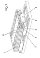
- a linear motor according to the invention is shown in the moving part a Housing 1 of continuous casting, which comprises at least one inventive Bearing is connected to carriage 4.
- a part of the housing. 1 cut out so that the sliding block 3 is better visible.
- the section visible visible part enlarged.
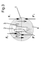
- this is a symbolic one Section shown, with which the power flows are made easier to understand.
- the linear motor is movable on two spaced rails 6, wherein the Carriage 4 with recirculating ball bearing or plain bearings are executable.
- the housing 1 surrounds the coil windings 7 of the linear motor. Depending on the imported electrical power heats up the coils and thus lead to accordingly local heating of the housing 1. As a result, find appropriate Length expansions and corresponding deformations take place on the housing. To the Compensate these deformations, the housing is on a first side by means of floating bearing mounted on the first rail associated carriage 4 and at a second Side stored by means of fixed bearing on the guide rail associated with the second rail.
- the length expansion is compensated at the floating bearing side such that no unacceptably high forces acting on the carriage 4. Furthermore, it is now at the Fixed bearing side a measuring system for the detection of the linear position and / or speed attachable, with thermally induced disturbances of the measuring system can be greatly reduced. In particular, the measuring system is mounted on the outside and thus as far as possible away from the areas of thermal heating.
- the reactive part in particular the secondary part of the linear motor, is direct or at others Embodiments according to the invention indirectly with the guide rails running rails 6 connected. Between the rails are the magnets of the Linear motor glued to the base plate of the reactive part and with a reactive part counting cover plate 8 provided.
- the housing 1 is provided with cooling fins as a cooling device.
- the housing faces also a standardized interface for connecting other devices.
- the mentioned length expansions may under certain circumstances also other or other Causes have, such as mechanical stresses, from one to the housing 1 connected further device caused. Other causes are also production-related tolerances.
- the mounting direction of the linear motor is not fixed.
- the assembly be executed so that the direction of gravity from the housing 1 to the magnets and their Cover plate 8 is directed or vice versa.
- FIG. 3 is a symbolic corresponding section, the technical operation illustrated.
- the housing 1 has a plurality of grooves oriented perpendicular to the continuous casting direction are. In the figure 2, the housing is cut out in this area. The direction These grooves define the direction of the degree of freedom of the floating bearing.
- a sliding block 3 is provided in each case, fixed with the carriage 4 connected is.
- the Carriage also in one piece with the sliding block 3 or equivalent, functional equivalent shape executable.
- the sliding block 3 together with the groove also all other mechanical linear guide types usable.
- Each sliding block 3 is fixed by means of a connecting screw 2 with the carriage 4 connected.
- the groove for the sliding block 3 in the housing 1 is dimensioned such that the Housing 1 between carriage 4 and sliding block 3 is guided.
- the housing 1 does not have solid material around the sliding block 3 around exhibit. It suffices as much material as for the formation of the contact surface for the sliding block. 3 and the carriage 4 is necessary.
- Over the connecting screw 2 is free space, which is executable as a bore to access a tool for To allow connecting screw.
- a cooling medium for example, a gas, air, coolant or water can be used are. Through these recesses in addition the mass is lowered without the Stability is reduced or significantly reduced. These recesses are at Producing the continuous casting produced. Thus, no additional costs or expenses for their production.
- the housing 1 is connected with low play with the carriage 4 and it is a thermally or otherwise conditional length expansion compensated in the direction of the groove.
- the friction can be selected within wide limits, that during the shift occurs.
- the housing 1 is made of aluminum, since the cooling fins a represent highly complex surface.
- the carriage 4 and the sliding block 3, however are made of steel or cast inexpensive and mechanically stable. Likewise, too Connecting screws 2 made of steel vorsehbar.
- the invention is also applicable to all rail vehicles, the at least two rails and one over carriages or wheels stored include mobile part. Those to be compensated by the floating bearing points Length expansions need not necessarily be thermally conditioned, but may also have other causes.
- the floating bearing point can also be used in other devices in which a Expansion in one direction is to compensate.
- the use of a groove and a slot nut 3 provided therein according to Figure 3 is also in others Applicable devices advantageous.
- the number of movable storage locations is variable as well as the number of floating bearing points with sliding blocks. Instead of the sliding block 3 are also suitably shaped other parts usable.
- the coil windings are separate arranged from the housing 1.
- Low backlash advantageously means a linear play of less than 20 microns.
Landscapes
- Engineering & Computer Science (AREA)
- General Engineering & Computer Science (AREA)
- Mechanical Engineering (AREA)
- Bearings For Parts Moving Linearly (AREA)
- Fittings On The Vehicle Exterior For Carrying Loads, And Devices For Holding Or Mounting Articles (AREA)
- Platform Screen Doors And Railroad Systems (AREA)
- Transmission Devices (AREA)
- Braking Arrangements (AREA)
- Linear Motors (AREA)
Abstract
wobei das dritte Teil mit einem zweiten Teil lösbar und/oder fest verbunden ist,
wobei das erste und dritte Teil eine gegenseitige Berührfläche aufweisen,
wobei das erste Teil mittels des zweiten Teils auf das dritte Teil gepresst ist,
wobei bei entsprechender Krafteinwirkung das erste Teil in einer ersten Richtung relativ zum dritten Teil verschiebbar angeordnet ist,
wobei eine zur ersten Richtung senkrecht gerichtete Kraft spielarm übertragbar ist vom ersten zum dritten Teil.
Description
wobei das erste Teil mittels des zweiten Teils auf das dritte Teil gepresst ist,
wobei bei entsprechender Krafteinwirkung das erste Teil in einer ersten Richtung relativ zum dritten Teil verschiebbar angeordnet ist,
wobei eine zur ersten Richtung senkrecht gerichtete Kraft spielarm übertragbar ist vom ersten zum dritten Teil.
- 1
- Gehäuse
- 2
- Verbindungsschraube
- 3
- Nutenstein
- 4
- Führungswagen
- 5
- Stift
- 6
- Schiene
- 7
- Spulenwicklungen
- 8
- Abdeckplatte
Claims (20)
- Loslagerstelle zum Lagern eines ersten Teils auf ein drittes Teil, insbesondere mit einem Freiheitsgrad,
wobei das dritte Teil mit einem zweiten Teil lösbar und/oder fest verbunden ist,
dadurch gekennzeichnet, dass
das erste und dritte Teil eine gegenseitige Berührfläche aufweisen
wobei das erste Teil mittels des zweiten Teils auf das dritte Teil gepresst ist,
wobei bei entsprechender Krafteinwirkung das erste Teil in einer ersten Richtung relativ zum dritten Teil verschiebbar angeordnet ist,
wobei eine zur ersten Richtung senkrecht gerichtete Kraft spielarm übertragbar ist vom ersten zum dritten Teil. - Loslager nach mindestens einem der vorangegangenen Ansprüche,
dadurch gekennzeichnet, dass
erstes und zweites Teil identisch sind, also aus einem Stück ausgeführt sind. - Loslager nach mindestens einem der vorangegangenen Ansprüche,
dadurch gekennzeichnet, dass
das zweite Teil derart in einer Nut des ersten Teils vorgesehen ist, dass der Freiheitsgrad des Loslagers derart gerichtet ist, dass Bewegungen des ersten Teils entlang der Nut ausführbar sind, insbesondere thermisch bedingte Ausdehnungen in Richtung der Nut. - Loslager nach mindestens einem der vorangegangenen Ansprüche,
dadurch gekennzeichnet, dass
erstes und drittes Teil jeweils aus verschiedenen Materialien gefertigt sind - Loslager nach mindestens einem der vorangegangenen Ansprüche,
dadurch gekennzeichnet, dass
das zweite Teil mittels einer Verbindungsschraube 2 mit dem dritten Teil lösbar verbunden ist. - Loslager nach mindestens einem der vorangegangenen Ansprüche,
dadurch gekennzeichnet, dass
das erste, zweite und/oder dritte Teil aus mindestens zwei fest verbundenen Teilen aufgebaut ist. - Loslager nach mindestens einem der vorangegangenen Ansprüche,
dadurch gekennzeichnet, dass
das erste Teil ein Gehäuse ist, das zweite Teil ein Nutenstein und/oder das dritte Teil ein Führungswagen. - Loslager nach mindestens einem der vorangegangenen Ansprüche,
dadurch gekennzeichnet, dass
Stifte zur Fixierung der in jeweilige Nuten des Gehäuses eingeführten Nutensteine bei Montage einbringbar sind. - Schienenfahrzeug, das auf mindestens zwei, zueinander parallel angeordneten Schienen bewegbar angeordnet ist,
wobei das Schienenfahrzeug mindestens einen Führungswagen für jede Schiene umfasst,
dadurch gekennzeichnet, dass
das Schienenfahrzeug zu einem ersten der einer ersten Schiene zugeordneten Führungswagen mindestens ein Festlager aufweist und
das Schienenfahrzeug zu einem ersten der einer zweiten Schiene zugeordneten Führungswägen mindestens ein Loslager nach mindestens einem der vorangegangenen Ansprüche aufweist. - Schienenfahrzeug nach mindestens einem der vorangegangenen Ansprüche,
dadurch gekennzeichnet, dass
das Gehäuse ein Stranggussteil ist. - Schienenfahrzeug nach mindestens einem der vorangegangenen Ansprüche,
dadurch gekennzeichnet, dass
die Verbindungsschrauben in eine Ausnehmung zur Wärmeabfuhr des Gehäuses hineinragen, die beim Herstellen mittels Stranggussverfahren erzeugt ist. - Schienenfahrzeug nach mindestens einem der vorangegangenen Ansprüche,
dadurch gekennzeichnet, dass
die Berührfläche zwischen Gehäuse und Führungswagen derart ausgeführt ist, dass Wärme vom Gehäuse an den Führungswagen abführbar ist. - Schienenfahrzeug nach mindestens einem der vorangegangenen Ansprüche,
dadurch gekennzeichnet, dass
zur Erfassung der Position und/oder Geschwindigkeit ein Messsystem vom Schienenfahrzeug umfasst ist, das näher am Festlager als am Loslager angeordnet ist. - Schienenfahrzeug nach mindestens einem der vorangegangenen Ansprüche,
dadurch gekennzeichnet, dass
das Schienenfahrzeug ein Linearmotor ist. - Schienenfahrzeug nach mindestens einem der vorangegangenen Ansprüche,
dadurch gekennzeichnet, dass
der Linearmotor als Synchronmotor ausgeführt ist. - Schienenfahrzeug nach mindestens einem der vorangegangenen Ansprüche,
dadurch gekennzeichnet, dass
das dritte Teil Spulen des Linearmotors umfasst. - Schienenfahrzeug nach mindestens einem der vorangegangenen Ansprüche,
dadurch gekennzeichnet, dass
das Schienenfahrzeug Mittel derart umfasst, dass die Spulen berührungslos mit Energie versorgbar sind. - Schienenfahrzeug nach mindestens einem der vorangegangenen Ansprüche,
dadurch gekennzeichnet, dass
das dritte Teil eine Kühlvorrichtung, wie Kühlrippen oder Kühlfinger, umfasst. - Schienenfahrzeug nach mindestens einem der vorangegangenen Ansprüche,
dadurch gekennzeichnet, dass
das dritte Teil eine Schnittstelle zum Verbinden mit weiteren Vorrichtungen umfasst. - Schienenfahrzeug nach mindestens einem der vorangegangenen Ansprüche,
dadurch gekennzeichnet, dass
die Schnittstelle regelmäßig voneinander beabstandete Bohrungen umfasst.
Applications Claiming Priority (2)
| Application Number | Priority Date | Filing Date | Title |
|---|---|---|---|
| DE10345068 | 2003-09-26 | ||
| DE10345068.8A DE10345068B4 (de) | 2003-09-26 | 2003-09-26 | Schienenfahrzeug |
Publications (3)
| Publication Number | Publication Date |
|---|---|
| EP1519059A2 true EP1519059A2 (de) | 2005-03-30 |
| EP1519059A3 EP1519059A3 (de) | 2007-03-07 |
| EP1519059B1 EP1519059B1 (de) | 2008-11-26 |
Family
ID=34178002
Family Applications (1)
| Application Number | Title | Priority Date | Filing Date |
|---|---|---|---|
| EP04017954A Expired - Lifetime EP1519059B1 (de) | 2003-09-26 | 2004-07-29 | Schienenfahrzeug und Loslagerstelle |
Country Status (3)
| Country | Link |
|---|---|
| EP (1) | EP1519059B1 (de) |
| AT (1) | ATE415729T1 (de) |
| DE (2) | DE10345068B4 (de) |
Cited By (3)
| Publication number | Priority date | Publication date | Assignee | Title |
|---|---|---|---|---|
| CN105904299A (zh) * | 2016-05-11 | 2016-08-31 | 周玉红 | 一种钢板平整度高精度磨平组件 |
| CN108533610A (zh) * | 2018-06-29 | 2018-09-14 | 昆山索莱能光电科技有限公司 | 一种直线运动模组 |
| CN112879427A (zh) * | 2021-03-01 | 2021-06-01 | 东台超德机械有限公司 | 一种带有便于拆装滑块的低组直线导轨 |
Family Cites Families (9)
| Publication number | Priority date | Publication date | Assignee | Title |
|---|---|---|---|---|
| GB1095391A (de) * | ||||
| DE469955C (de) | 1929-01-02 | Reichert Fa C | Elastische Tubusfuehrung fuer Mikroskope | |
| US4264112A (en) | 1979-08-06 | 1981-04-28 | Lee Controls, Inc. | Floating pillow blocks |
| DE9407329U1 (de) | 1994-05-03 | 1994-07-07 | Bonanno, Antonio, 61440 Oberursel | Verbindungselement |
| DE19604642A1 (de) * | 1996-02-08 | 1997-08-14 | Krauss Maffei Ag | Linearmotor |
| DE19722171A1 (de) | 1997-05-27 | 1998-12-10 | Star Gmbh | Läuferbaugruppe für eine Linearführungseinrichtung |
| DE19815474A1 (de) | 1998-04-07 | 1999-10-21 | Bosch Gmbh Robert | Lineareinheit mit einer Gleitführung für einen Schlitten |
| DE19842384A1 (de) | 1998-09-16 | 2000-03-23 | Schaeffler Waelzlager Ohg | Linearführung |
| DE10256761B4 (de) * | 2002-11-20 | 2009-05-07 | Sew-Eurodrive Gmbh & Co. Kg | Schienenfahrzeug und eine Loslagerstelle |
-
2003
- 2003-09-26 DE DE10345068.8A patent/DE10345068B4/de not_active Expired - Lifetime
-
2004
- 2004-07-29 EP EP04017954A patent/EP1519059B1/de not_active Expired - Lifetime
- 2004-07-29 DE DE502004008518T patent/DE502004008518D1/de not_active Expired - Lifetime
- 2004-07-29 AT AT04017954T patent/ATE415729T1/de not_active IP Right Cessation
Cited By (4)
| Publication number | Priority date | Publication date | Assignee | Title |
|---|---|---|---|---|
| CN105904299A (zh) * | 2016-05-11 | 2016-08-31 | 周玉红 | 一种钢板平整度高精度磨平组件 |
| CN108533610A (zh) * | 2018-06-29 | 2018-09-14 | 昆山索莱能光电科技有限公司 | 一种直线运动模组 |
| CN112879427A (zh) * | 2021-03-01 | 2021-06-01 | 东台超德机械有限公司 | 一种带有便于拆装滑块的低组直线导轨 |
| CN112879427B (zh) * | 2021-03-01 | 2022-03-29 | 东台超德机械有限公司 | 一种带有便于拆装滑块的低阻直线导轨 |
Also Published As
| Publication number | Publication date |
|---|---|
| DE10345068A1 (de) | 2005-05-04 |
| DE10345068B4 (de) | 2019-10-24 |
| EP1519059B1 (de) | 2008-11-26 |
| DE502004008518D1 (de) | 2009-01-08 |
| EP1519059A3 (de) | 2007-03-07 |
| ATE415729T1 (de) | 2008-12-15 |
Similar Documents
| Publication | Publication Date | Title |
|---|---|---|
| EP1338077B1 (de) | Retarder, insbesondere als brems- oder zusatzbremseinrichtung für fahrzeuge oder dergleichen, insbesondere schienenfahrzeuge | |
| EP2088664B1 (de) | Maschine mit Direktantrieb | |
| DE112006003352B4 (de) | XY-Tisch-Stellglied | |
| DE102004043606A1 (de) | Stellglied | |
| DE29700643U1 (de) | Entwärmungskonzept für ein elektrisches Antriebssystem | |
| DE4301434A1 (de) | Linearführungsanordnung mit Ausgleichsmitteln für mechanische Spannungen | |
| EP2259896B9 (de) | Linearantrieb für eine werkzeugmaschine und verfahren zur bewegung eines werkzeugschlittens | |
| EP0790421A1 (de) | Linearführung | |
| DE10345068B4 (de) | Schienenfahrzeug | |
| DE10320553B4 (de) | Linearmotor | |
| DE102013226826A1 (de) | Linearmotoranordnung und Werkzeugmaschine mit einer Linearmotoranordnung | |
| EP4017679B1 (de) | Hochpräzisions-werkzeugmaschine mit linearem antriebs- und führungslager | |
| DE10256761B4 (de) | Schienenfahrzeug und eine Loslagerstelle | |
| DE102007037886B4 (de) | Feldgeführter planarer Präzisionsantrieb mit einem luftgelagerten Läufer | |
| DE19948490C2 (de) | Lineardirektantrieb | |
| DE19700392A1 (de) | Antriebsvorrichtung mit mehreren flachen Linearmotoren | |
| EP1619281A1 (de) | Legebarrenantrieb in einer Wirkmaschine | |
| DE102013111169B4 (de) | Prüfzylinder und Prüfmaschine | |
| EP2293418B1 (de) | Linearmotorsystem | |
| DE102008015686B4 (de) | Antrieb und Vorrichtung | |
| DE102009008882B4 (de) | Lineardirektantrieb | |
| DE102008059607A1 (de) | Vorrichtung zum Stanzen | |
| DE112018001740B4 (de) | Rotationsmaschine | |
| EP1378319B1 (de) | Antriebssystem mit Linearmotoren sowie Vorschubachse einer Werkzeugmaschine mit einem solchen Antriebssystem | |
| DE19961869B4 (de) | Justiervorrichtung, insbesondere für Traversen mit Bebilderungseinrichtungen für Druckformen von Druckmaschinen |
Legal Events
| Date | Code | Title | Description |
|---|---|---|---|
| PUAI | Public reference made under article 153(3) epc to a published international application that has entered the european phase |
Free format text: ORIGINAL CODE: 0009012 |
|
| AK | Designated contracting states |
Kind code of ref document: A2 Designated state(s): AT BE BG CH CY CZ DE DK EE ES FI FR GB GR HU IE IT LI LU MC NL PL PT RO SE SI SK TR |
|
| AX | Request for extension of the european patent |
Extension state: AL HR LT LV MK |
|
| PUAL | Search report despatched |
Free format text: ORIGINAL CODE: 0009013 |
|
| AK | Designated contracting states |
Kind code of ref document: A3 Designated state(s): AT BE BG CH CY CZ DE DK EE ES FI FR GB GR HU IE IT LI LU MC NL PL PT RO SE SI SK TR |
|
| AX | Request for extension of the european patent |
Extension state: AL HR LT LV MK |
|
| RIC1 | Information provided on ipc code assigned before grant |
Ipc: B61B 13/08 20060101ALI20070131BHEP Ipc: B23Q 5/28 20060101ALI20070131BHEP Ipc: F16C 29/00 20060101ALI20070131BHEP Ipc: H02K 41/03 20060101AFI20070131BHEP Ipc: B23Q 1/56 20060101ALI20070131BHEP |
|
| 17P | Request for examination filed |
Effective date: 20070907 |
|
| AKX | Designation fees paid |
Designated state(s): AT BE BG CH CY CZ DE DK EE ES FI FR GB GR HU IE IT LI LU MC NL PL PT RO SE SI SK TR |
|
| 17Q | First examination report despatched |
Effective date: 20080207 |
|
| GRAP | Despatch of communication of intention to grant a patent |
Free format text: ORIGINAL CODE: EPIDOSNIGR1 |
|
| GRAS | Grant fee paid |
Free format text: ORIGINAL CODE: EPIDOSNIGR3 |
|
| GRAA | (expected) grant |
Free format text: ORIGINAL CODE: 0009210 |
|
| AK | Designated contracting states |
Kind code of ref document: B1 Designated state(s): AT BE BG CH CY CZ DE DK EE ES FI FR GB GR HU IE IT LI LU MC NL PL PT RO SE SI SK TR |
|
| REG | Reference to a national code |
Ref country code: GB Ref legal event code: FG4D Free format text: NOT ENGLISH |
|
| REG | Reference to a national code |
Ref country code: CH Ref legal event code: NV Representative=s name: HEPP WENGER RYFFEL AG Ref country code: CH Ref legal event code: EP |
|
| REG | Reference to a national code |
Ref country code: IE Ref legal event code: FG4D Free format text: LANGUAGE OF EP DOCUMENT: GERMAN |
|
| REF | Corresponds to: |
Ref document number: 502004008518 Country of ref document: DE Date of ref document: 20090108 Kind code of ref document: P |
|
| PG25 | Lapsed in a contracting state [announced via postgrant information from national office to epo] |
Ref country code: ES Free format text: LAPSE BECAUSE OF FAILURE TO SUBMIT A TRANSLATION OF THE DESCRIPTION OR TO PAY THE FEE WITHIN THE PRESCRIBED TIME-LIMIT Effective date: 20090308 |
|
| NLV1 | Nl: lapsed or annulled due to failure to fulfill the requirements of art. 29p and 29m of the patents act | ||
| PG25 | Lapsed in a contracting state [announced via postgrant information from national office to epo] |
Ref country code: SI Free format text: LAPSE BECAUSE OF FAILURE TO SUBMIT A TRANSLATION OF THE DESCRIPTION OR TO PAY THE FEE WITHIN THE PRESCRIBED TIME-LIMIT Effective date: 20081126 Ref country code: NL Free format text: LAPSE BECAUSE OF FAILURE TO SUBMIT A TRANSLATION OF THE DESCRIPTION OR TO PAY THE FEE WITHIN THE PRESCRIBED TIME-LIMIT Effective date: 20081126 Ref country code: FI Free format text: LAPSE BECAUSE OF FAILURE TO SUBMIT A TRANSLATION OF THE DESCRIPTION OR TO PAY THE FEE WITHIN THE PRESCRIBED TIME-LIMIT Effective date: 20081126 Ref country code: PL Free format text: LAPSE BECAUSE OF FAILURE TO SUBMIT A TRANSLATION OF THE DESCRIPTION OR TO PAY THE FEE WITHIN THE PRESCRIBED TIME-LIMIT Effective date: 20081126 |
|
| REG | Reference to a national code |
Ref country code: IE Ref legal event code: FD4D |
|
| PG25 | Lapsed in a contracting state [announced via postgrant information from national office to epo] |
Ref country code: RO Free format text: LAPSE BECAUSE OF FAILURE TO SUBMIT A TRANSLATION OF THE DESCRIPTION OR TO PAY THE FEE WITHIN THE PRESCRIBED TIME-LIMIT Effective date: 20081126 Ref country code: BG Free format text: LAPSE BECAUSE OF FAILURE TO SUBMIT A TRANSLATION OF THE DESCRIPTION OR TO PAY THE FEE WITHIN THE PRESCRIBED TIME-LIMIT Effective date: 20090226 Ref country code: DK Free format text: LAPSE BECAUSE OF FAILURE TO SUBMIT A TRANSLATION OF THE DESCRIPTION OR TO PAY THE FEE WITHIN THE PRESCRIBED TIME-LIMIT Effective date: 20081126 Ref country code: EE Free format text: LAPSE BECAUSE OF FAILURE TO SUBMIT A TRANSLATION OF THE DESCRIPTION OR TO PAY THE FEE WITHIN THE PRESCRIBED TIME-LIMIT Effective date: 20081126 Ref country code: IE Free format text: LAPSE BECAUSE OF FAILURE TO SUBMIT A TRANSLATION OF THE DESCRIPTION OR TO PAY THE FEE WITHIN THE PRESCRIBED TIME-LIMIT Effective date: 20081126 |
|
| PG25 | Lapsed in a contracting state [announced via postgrant information from national office to epo] |
Ref country code: SE Free format text: LAPSE BECAUSE OF FAILURE TO SUBMIT A TRANSLATION OF THE DESCRIPTION OR TO PAY THE FEE WITHIN THE PRESCRIBED TIME-LIMIT Effective date: 20090226 Ref country code: PT Free format text: LAPSE BECAUSE OF FAILURE TO SUBMIT A TRANSLATION OF THE DESCRIPTION OR TO PAY THE FEE WITHIN THE PRESCRIBED TIME-LIMIT Effective date: 20090427 |
|
| PG25 | Lapsed in a contracting state [announced via postgrant information from national office to epo] |
Ref country code: SK Free format text: LAPSE BECAUSE OF FAILURE TO SUBMIT A TRANSLATION OF THE DESCRIPTION OR TO PAY THE FEE WITHIN THE PRESCRIBED TIME-LIMIT Effective date: 20081126 |
|
| PLBE | No opposition filed within time limit |
Free format text: ORIGINAL CODE: 0009261 |
|
| STAA | Information on the status of an ep patent application or granted ep patent |
Free format text: STATUS: NO OPPOSITION FILED WITHIN TIME LIMIT |
|
| 26N | No opposition filed |
Effective date: 20090827 |
|
| BERE | Be: lapsed |
Owner name: SEW-EURODRIVE G.M.B.H. & CO. KG Effective date: 20090731 |
|
| PG25 | Lapsed in a contracting state [announced via postgrant information from national office to epo] |
Ref country code: MC Free format text: LAPSE BECAUSE OF NON-PAYMENT OF DUE FEES Effective date: 20090731 |
|
| PG25 | Lapsed in a contracting state [announced via postgrant information from national office to epo] |
Ref country code: BE Free format text: LAPSE BECAUSE OF NON-PAYMENT OF DUE FEES Effective date: 20090731 |
|
| PG25 | Lapsed in a contracting state [announced via postgrant information from national office to epo] |
Ref country code: GR Free format text: LAPSE BECAUSE OF FAILURE TO SUBMIT A TRANSLATION OF THE DESCRIPTION OR TO PAY THE FEE WITHIN THE PRESCRIBED TIME-LIMIT Effective date: 20090227 |
|
| PG25 | Lapsed in a contracting state [announced via postgrant information from national office to epo] |
Ref country code: AT Free format text: LAPSE BECAUSE OF NON-PAYMENT OF DUE FEES Effective date: 20090729 |
|
| PG25 | Lapsed in a contracting state [announced via postgrant information from national office to epo] |
Ref country code: IT Free format text: LAPSE BECAUSE OF FAILURE TO SUBMIT A TRANSLATION OF THE DESCRIPTION OR TO PAY THE FEE WITHIN THE PRESCRIBED TIME-LIMIT Effective date: 20081126 |
|
| PG25 | Lapsed in a contracting state [announced via postgrant information from national office to epo] |
Ref country code: LU Free format text: LAPSE BECAUSE OF NON-PAYMENT OF DUE FEES Effective date: 20090729 |
|
| PG25 | Lapsed in a contracting state [announced via postgrant information from national office to epo] |
Ref country code: HU Free format text: LAPSE BECAUSE OF FAILURE TO SUBMIT A TRANSLATION OF THE DESCRIPTION OR TO PAY THE FEE WITHIN THE PRESCRIBED TIME-LIMIT Effective date: 20090527 |
|
| PG25 | Lapsed in a contracting state [announced via postgrant information from national office to epo] |
Ref country code: TR Free format text: LAPSE BECAUSE OF FAILURE TO SUBMIT A TRANSLATION OF THE DESCRIPTION OR TO PAY THE FEE WITHIN THE PRESCRIBED TIME-LIMIT Effective date: 20081126 |
|
| PG25 | Lapsed in a contracting state [announced via postgrant information from national office to epo] |
Ref country code: CY Free format text: LAPSE BECAUSE OF FAILURE TO SUBMIT A TRANSLATION OF THE DESCRIPTION OR TO PAY THE FEE WITHIN THE PRESCRIBED TIME-LIMIT Effective date: 20081126 |
|
| REG | Reference to a national code |
Ref country code: FR Ref legal event code: PLFP Year of fee payment: 13 |
|
| REG | Reference to a national code |
Ref country code: FR Ref legal event code: PLFP Year of fee payment: 14 |
|
| REG | Reference to a national code |
Ref country code: FR Ref legal event code: PLFP Year of fee payment: 15 |
|
| PGFP | Annual fee paid to national office [announced via postgrant information from national office to epo] |
Ref country code: FR Payment date: 20230608 Year of fee payment: 20 Ref country code: CZ Payment date: 20230616 Year of fee payment: 20 |
|
| PGFP | Annual fee paid to national office [announced via postgrant information from national office to epo] |
Ref country code: GB Payment date: 20230608 Year of fee payment: 20 |
|
| PGFP | Annual fee paid to national office [announced via postgrant information from national office to epo] |
Ref country code: DE Payment date: 20230731 Year of fee payment: 20 |
|
| PGFP | Annual fee paid to national office [announced via postgrant information from national office to epo] |
Ref country code: CH Payment date: 20231005 Year of fee payment: 20 |
|
| REG | Reference to a national code |
Ref country code: DE Ref legal event code: R071 Ref document number: 502004008518 Country of ref document: DE |
|
| REG | Reference to a national code |
Ref country code: CH Ref legal event code: PL |
|
| REG | Reference to a national code |
Ref country code: GB Ref legal event code: PE20 Expiry date: 20240728 |
|
| PG25 | Lapsed in a contracting state [announced via postgrant information from national office to epo] |
Ref country code: GB Free format text: LAPSE BECAUSE OF EXPIRATION OF PROTECTION Effective date: 20240728 |
|
| PG25 | Lapsed in a contracting state [announced via postgrant information from national office to epo] |
Ref country code: CZ Free format text: LAPSE BECAUSE OF EXPIRATION OF PROTECTION Effective date: 20240729 |
|
| PG25 | Lapsed in a contracting state [announced via postgrant information from national office to epo] |
Ref country code: GB Free format text: LAPSE BECAUSE OF EXPIRATION OF PROTECTION Effective date: 20240728 Ref country code: CZ Free format text: LAPSE BECAUSE OF EXPIRATION OF PROTECTION Effective date: 20240729 |