EP1518981B1 - Poignée de porte extérieure - Google Patents
Poignée de porte extérieure Download PDFInfo
- Publication number
- EP1518981B1 EP1518981B1 EP20030019060 EP03019060A EP1518981B1 EP 1518981 B1 EP1518981 B1 EP 1518981B1 EP 20030019060 EP20030019060 EP 20030019060 EP 03019060 A EP03019060 A EP 03019060A EP 1518981 B1 EP1518981 B1 EP 1518981B1
- Authority
- EP
- European Patent Office
- Prior art keywords
- door handle
- external door
- lead
- handle according
- shield
- Prior art date
- Legal status (The legal status is an assumption and is not a legal conclusion. Google has not performed a legal analysis and makes no representation as to the accuracy of the status listed.)
- Expired - Lifetime
Links
- 239000000463 material Substances 0.000 claims description 10
- VYZAMTAEIAYCRO-UHFFFAOYSA-N Chromium Chemical compound [Cr] VYZAMTAEIAYCRO-UHFFFAOYSA-N 0.000 claims description 2
- ATJFFYVFTNAWJD-UHFFFAOYSA-N Tin Chemical compound [Sn] ATJFFYVFTNAWJD-UHFFFAOYSA-N 0.000 claims description 2
- 239000011888 foil Substances 0.000 claims description 2
- 229910052751 metal Inorganic materials 0.000 claims 3
- 239000002184 metal Substances 0.000 claims 3
- 238000005476 soldering Methods 0.000 claims 2
- 229910052804 chromium Inorganic materials 0.000 claims 1
- 239000011651 chromium Substances 0.000 claims 1
- 230000000977 initiatory effect Effects 0.000 claims 1
- 238000007747 plating Methods 0.000 claims 1
- 239000004020 conductor Substances 0.000 description 19
- 230000007797 corrosion Effects 0.000 description 4
- 238000005260 corrosion Methods 0.000 description 4
- 230000007613 environmental effect Effects 0.000 description 4
- 230000007257 malfunction Effects 0.000 description 3
- 238000013475 authorization Methods 0.000 description 2
- 230000004913 activation Effects 0.000 description 1
- 230000015572 biosynthetic process Effects 0.000 description 1
- 239000011248 coating agent Substances 0.000 description 1
- 238000000576 coating method Methods 0.000 description 1
- 238000002788 crimping Methods 0.000 description 1
- 230000001419 dependent effect Effects 0.000 description 1
- 239000000945 filler Substances 0.000 description 1
- 238000004519 manufacturing process Methods 0.000 description 1
- 230000007246 mechanism Effects 0.000 description 1
- 238000012986 modification Methods 0.000 description 1
- 230000004048 modification Effects 0.000 description 1
- 230000001960 triggered effect Effects 0.000 description 1
- 230000000007 visual effect Effects 0.000 description 1
Images


Classifications
-
- E—FIXED CONSTRUCTIONS
- E05—LOCKS; KEYS; WINDOW OR DOOR FITTINGS; SAFES
- E05B—LOCKS; ACCESSORIES THEREFOR; HANDCUFFS
- E05B81/00—Power-actuated vehicle locks
- E05B81/54—Electrical circuits
- E05B81/64—Monitoring or sensing, e.g. by using switches or sensors
- E05B81/76—Detection of handle operation; Detection of a user approaching a handle; Electrical switching actions performed by door handles
- E05B81/78—Detection of handle operation; Detection of a user approaching a handle; Electrical switching actions performed by door handles as part of a hands-free locking or unlocking operation
-
- E—FIXED CONSTRUCTIONS
- E05—LOCKS; KEYS; WINDOW OR DOOR FITTINGS; SAFES
- E05B—LOCKS; ACCESSORIES THEREFOR; HANDCUFFS
- E05B79/00—Mounting or connecting vehicle locks or parts thereof
- E05B79/02—Mounting of vehicle locks or parts thereof
- E05B79/06—Mounting of handles, e.g. to the wing or to the lock
-
- E—FIXED CONSTRUCTIONS
- E05—LOCKS; KEYS; WINDOW OR DOOR FITTINGS; SAFES
- E05B—LOCKS; ACCESSORIES THEREFOR; HANDCUFFS
- E05B81/00—Power-actuated vehicle locks
- E05B81/54—Electrical circuits
- E05B81/64—Monitoring or sensing, e.g. by using switches or sensors
- E05B81/76—Detection of handle operation; Detection of a user approaching a handle; Electrical switching actions performed by door handles
- E05B81/77—Detection of handle operation; Detection of a user approaching a handle; Electrical switching actions performed by door handles comprising sensors detecting the presence of the hand of a user
Definitions
- the invention relates to an outside door handle of the type referred to in the preamble of claim 1 (as known, for example, from US-A-5 340 174).
- the functions triggered by the capacitive sensor contained in the outside door handle may include, for example, an access authorization to the vehicle and serve for more comfortable opening and closing.
- the corresponding outside door handles have one or more functional surfaces via which the capacitive sensor can be addressed.
- a disadvantage of such an arrangement is that it may cause interference of the capacitive sensors and so an unwanted operation or locking of the door mechanism is done. These disturbances lead to malfunctions and thus to energy loss.
- the disturbances often come about through environmental influences, such as rain or increased humidity.
- the outside door handle also has a second or even additional functional areas are additionally accompanied by the problem that the capacitive sensors of the different functional areas influence one another and thus further malfunctions occur.
- the object of the invention is therefore to avoid the aforementioned disadvantages and to provide a cost-effective outside door handle with at least one capacitive sensor, which works trouble-free despite environmental impact.
- This is inventively achieved by the measures mentioned in claim 1, which has the following special significance.
- Such a screw connection which additionally generates a clamping pressure, is simple and inexpensive to produce. It represents an effective and quick way of contacting the panel with the ground potential of the vehicle.
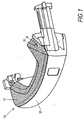
- the outside door handle 10 shown in Fig. 1 consists of an electrically conductive aperture 11 and a handle portion 12. These two parts are connected by a connecting means 14 with each other.
- the aperture 11 is often made of chrome or chromium-plated material, which is easy and inexpensive to manufacture and has a nice visual effect.
- a capacitive sensor 20 which serves to trigger functions on the vehicle. These functions may be, for example, that the vehicle automatically opens and closes after the access authorization of the person operating the outside door handle has been established. Other examples include the start-up of open windows or the activation of the alarm system of the vehicle.
- the electrically conductive diaphragm 11 is connected to the ground potential of the vehicle.
- the connection 21 to the ground potential is located in the interior 13 of the outside door handle 10.
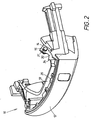
- This connection of the electrically conductive panel 11 to the terminal 21 of the ground potential is realized via an electrical conductor 30 and a screw 15, which also at the same time the connecting means 14 of the diaphragm 11 with the handle ridge 12 represents.
- An electrical conductor 30 is connected at its one end 31 via the screw 15 with the diaphragm 11, while the other end 32 of the conductor 30 is connected to the interior located in the handle 13 terminal 21 of the ground potential of the vehicle.
- This conductor 30 connects so easily and inexpensively, the aperture 11 with the ground potential of the vehicle.
- the electrical conductor 30 is designed as a metallic tongue 34.
- This has a hole 35 through which the screw 15 is guided.
- the hole 35 at the end 31 of the metallic tongue 34 is designed as a plate spring 36.
- the plate spring 36 is generated by crimping the inner edge 37 around the hole 35 around. If now a clamping pressure 16 is generated by tightening the screw 15, this is particularly secured by the special design of the metallic tongue 34.
- the plate spring 36 prevents namely the loosening of the screw 15 and amplifies the clamping pressure 16.
- the plate spring 36 additionally secures the connection between the Aperture 11 and the handle ridge 12, so that even with a flowing deformation of these two parts a connection is ensured.
- the electrical conductor 30 is a metallic wire 33 which is clamped by the screw 15.
- the metallic wire 33 may at its one end 31 and a ring or ring sector-like training, through which the screw 15 is guided. As a result, a better clamping of the metallic wire 33 comes about.
- the conductor 30 In order to avoid corrosion on the diaphragm 11 and / or the electrical conductor 30, it is advisable to produce the conductor 30 from a stainless sheet or wire whose potential of the electrochemical series is close to the potential of the material from which the diaphragm 11 consists. In fact, in the case of corrosion of the conductor 30, it would not be possible to ensure the continuity of the electrical connection between the diaphragm 11 and the terminal 21 of the ground potential of the vehicle. In addition, corrosion on the diaphragm 11 would still lead to an ugly appearance, which affects the attractiveness of the vehicle.
- the conductor 30 is connected to a in the handle interior 13 located film 22, which in turn is connected to the ground potential of the vehicle.
- a film 22 is space-saving and easy to assemble.
- the conductor 30 is soldered at its other end 32 to the terminal 21 of the ground potential, or with the film 22. This type of connection ensures a conductive connection that is easy to implement and does not require additional fasteners such as screws, rivets or the like.
- a prior at least partial coating of the conductor 30 with tin is advantageous.
- the handle interior 13 of the exterior door handle 10 is at least partially filled by its intended use with a filler to protect the electronics 20 from moisture and environmental influences.
- the embodiments shown here merely represent, for example, realizations of the invention. This is not limited thereto, but rather various modifications and designs are possible. So it is conceivable, for example, to provide the handle remainder directly with a shape that represents the connection to the ground potential of the vehicle or the connection to the ground potential in such a way that the aperture can be connected directly via the screw, without the use of an electrical conductor , Furthermore, other embodiments of the electrical conductor are conceivable.
- the one end of the conductor may have various shapes, for example, form a half or partial ring and / or be provided with leaf springs.
Landscapes
- Lock And Its Accessories (AREA)
Claims (13)
- poignée extérieure de portière (10) pour véhicules automobiles, comprenant au moins un capteur (20) capacitif pour déclencher des fonctions sur le véhicule,
la poignée (10) présentant, par zones, un écran (11) conducteur de l'électricité,
et étant en outre formée d'un reste de poignée (12), relié à l'écran (11) par un moyen de liaison (14),
et comprenant en outre une partie intérieure de poignée (13), un raccordement (21) au potentiel de masse du véhicule se trouvant dans la partie intérieure de poignée (13),
caractérisée en ce que
l'élément de liaison (14) constitue une vis (15) entre l'écran (11) et le reste de poignée (12)
et en ce que la vis (15) produit un pressage par serrage (16), reliant l'écran (11) au raccordement (21) du potentiel de masse. - Poignée extérieure de portière selon la revendication 1, caractérisée en ce qu'un conducteur électrique (30) est relié, à une extrémité (31), par l'intermédiaire de la vis (15), à l'écran (11),
tandis que l'autre extrémité (32) du conducteur (30) est raccordée au raccordement (21) du potentiel de masse. - Poignée extérieure de portière selon la revendication 2, caractérisée en ce que le conducteur (30) est formé d'un fil (33) métallique.
- Poignée extérieure de portière selon la revendication 2, caractérisée en ce que le conducteur (30) est réalisé sous la forme de languette métallique (34).
- Poignée extérieure de portière selon l'une des revendications 3 ou 4, caractérisée en ce que le conducteur (30) présente ou forme un trou (35), à travers lequel la vis (15) est guidée.
- Poignée extérieure de portière selon l'une des revendications 4 ou 5, caractérisée en ce que la languette (34) forme, sur l'extrémité (31) mise en contact avec l'écran (11), un ressort à disque (36), à travers lequel la vis (15) est guidée.
- Poignée extérieure de portière selon l'une des revendications 1 à 6, caractérisée en ce que l'écran (11) est formé de chrome ou de matériau chromé.
- Poignée extérieure de portière selon l'une des revendications 2 à 7, caractérisée en ce que le conducteur (30) est formé d'une tôle ne se corrodant pas, dont le potentiel de la rangée de tension électrochimique est proche du potentiel du matériau, à partir duquel l'écran (11) est formé.
- Poignée extérieure de portière selon l'une des revendications 1 à 8, caractérisée en ce que le conducteur (30) est raccordé, à la partie intérieure (13), à une feuille (22) reliée à son tour au potentiel de masse du véhicule.
- Poignée extérieure de portière selon l'une des revendications 1 à 9, caractérisée en ce que le conducteur (30) est relié par brasage au raccordement (21) du potentiel de masse.
- Poignée extérieure de portière selon la revendications 10, caractérisée en ce que le matériau du conducteur (30) est rendu brasable par au moins un revêtement partiel avec de l'étain.
- Poignée extérieure de portière selon l'une des revendications 1 à 11, caractérisée en ce que la poignée intérieure de poignée (13) de la poignée extérieure de portière (10) est remplie, au moins partiellement, d'un matériau de remplissage avant l'utilisation nominale.
- Poignée extérieure de portière selon la revendication 12, caractérisée en ce que l'autre extrémité (32) du conducteur (30), raccordée au raccordement (21) du potentiel de masse, est située à l'intérieur de la zone remplie du matériau de charge.
Priority Applications (2)
| Application Number | Priority Date | Filing Date | Title |
|---|---|---|---|
| EP20030019060 EP1518981B1 (fr) | 2003-08-29 | 2003-08-29 | Poignée de porte extérieure |
| DE50302366T DE50302366D1 (de) | 2003-08-29 | 2003-08-29 | Türaussengriff |
Applications Claiming Priority (1)
| Application Number | Priority Date | Filing Date | Title |
|---|---|---|---|
| EP20030019060 EP1518981B1 (fr) | 2003-08-29 | 2003-08-29 | Poignée de porte extérieure |
Publications (2)
| Publication Number | Publication Date |
|---|---|
| EP1518981A1 EP1518981A1 (fr) | 2005-03-30 |
| EP1518981B1 true EP1518981B1 (fr) | 2006-02-08 |
Family
ID=34178392
Family Applications (1)
| Application Number | Title | Priority Date | Filing Date |
|---|---|---|---|
| EP20030019060 Expired - Lifetime EP1518981B1 (fr) | 2003-08-29 | 2003-08-29 | Poignée de porte extérieure |
Country Status (2)
| Country | Link |
|---|---|
| EP (1) | EP1518981B1 (fr) |
| DE (1) | DE50302366D1 (fr) |
Families Citing this family (5)
| Publication number | Priority date | Publication date | Assignee | Title |
|---|---|---|---|---|
| DE102005031454A1 (de) * | 2005-07-04 | 2007-01-11 | Huf Hülsbeck & Fürst Gmbh & Co. Kg | Türgriff, Türgriff-Gehäuse und Verfahren zum Herstellen des Türgriff-Gehäuses |
| DE102006055100A1 (de) * | 2006-11-21 | 2008-05-29 | Kiekert Ag | Türgriff mit Blende und Elektronikbauteil-Träger |
| IT1392399B1 (it) | 2008-12-22 | 2012-03-02 | Valeo Spa | Maniglia per porta di autoveicolo |
| DE102014107977A1 (de) * | 2014-06-05 | 2015-12-17 | Witte Automotive Gmbh | Türgriff mit Sensor |
| DE102021126043A1 (de) | 2021-10-07 | 2023-04-13 | Minebea Mitsumi Inc. | Sensorvorrichtung eines türgriffs für ein kraftfahrzeug |
Family Cites Families (3)
| Publication number | Priority date | Publication date | Assignee | Title |
|---|---|---|---|---|
| GB8701875D0 (en) * | 1987-01-28 | 1987-03-04 | Rolls Royce Motor Cars | Handle assembly |
| US5340174A (en) * | 1993-04-12 | 1994-08-23 | Chrysler Corporation | Mounting arrangement for vehicle door handle |
| DE10048917A1 (de) * | 2000-10-04 | 2002-04-18 | Huf Huelsbeck & Fuerst Gmbh | Griff für Türen oder Klappen, insbesondere bei Fahrzeugen |
-
2003
- 2003-08-29 EP EP20030019060 patent/EP1518981B1/fr not_active Expired - Lifetime
- 2003-08-29 DE DE50302366T patent/DE50302366D1/de not_active Expired - Lifetime
Also Published As
| Publication number | Publication date |
|---|---|
| EP1518981A1 (fr) | 2005-03-30 |
| DE50302366D1 (de) | 2006-04-20 |
Similar Documents
| Publication | Publication Date | Title |
|---|---|---|
| DE60211173T2 (de) | Griff für kraftfahrzeugflügel | |
| DE102008035634B4 (de) | Schaltleiste für die Erfassung von Hindernissen und Vorrichtung zum Erfassen von Hindernissen | |
| EP2118411B1 (fr) | Poignée extérieure pour portières ou panneaux articulés de véhicules | |
| EP2795240B1 (fr) | Système de commande pour commander un élément de fermeture motorisé d'un véhicule | |
| DE69925089T2 (de) | Handhabe für Kraftfahrzeugschloss | |
| DE19742458C1 (de) | Kunststoffgehäuse zur Aufnahme einer elektrischen Leiterplatte | |
| DE10226133A1 (de) | Anordnung für eine Vorrichtung zum Erkennen eines Hindernisses in dem Öffnungsbereich eines bewegbaren Schließelements eines Kraftfahrzeugs | |
| EP2059421B1 (fr) | Manette | |
| AT391913B (de) | Einklemmschutz fuer fenster und tueren | |
| EP2010743A1 (fr) | Dispositif de protection antipincement commandé par capteur et véhicule associé | |
| EP1518981B1 (fr) | Poignée de porte extérieure | |
| EP0634550B1 (fr) | Fermeture tournante | |
| DE3126013A1 (de) | Glaskeramik-kochfeld | |
| DE9400748U1 (de) | Fernbedienungsgehäuse, insbesondere für eine Anlage zur elektrischen Verriegelung der zu öffnenden Teile eines Kraftfahrzeuges, und eine derartige Anlage | |
| DE102018008105B4 (de) | Kraftfahrzeugemblem mit integrierter Sensor- und Reinigungsvorrichtung | |
| WO2009152801A1 (fr) | Poignée extérieure de porte | |
| DE202005011044U1 (de) | Sensorsystem für eine Einklemmschutzvorrichtung | |
| DE19745869A1 (de) | Fahrzeugtür mit einem leitfähigen Element zur Ableitung elektrostatischer Aufladungen | |
| DE10306361B4 (de) | Türgriffanordnung für eine Kraftfahrzeugtür | |
| WO2016005368A1 (fr) | Module de détection permettant un actionnement sans contact d'un élément de véhicule déplaçable | |
| DE29706174U1 (de) | Langsensor für Dichtungsprofile einsetzbar in Zargenfugen als Signalauslöser | |
| DE102007024594A1 (de) | Außengriff an Türen oder Klappen von Fahrzeugen | |
| DE29705468U1 (de) | Scharnier zur Befestigung eines Türblattes an einem Korpus | |
| EP1432124A2 (fr) | Arrangement de transmission de données entre un émetteur et une unité de contrôle | |
| EP3113363B1 (fr) | Système de détection |
Legal Events
| Date | Code | Title | Description |
|---|---|---|---|
| PUAI | Public reference made under article 153(3) epc to a published international application that has entered the european phase |
Free format text: ORIGINAL CODE: 0009012 |
|
| GRAP | Despatch of communication of intention to grant a patent |
Free format text: ORIGINAL CODE: EPIDOSNIGR1 |
|
| 17P | Request for examination filed |
Effective date: 20040603 |
|
| AK | Designated contracting states |
Kind code of ref document: A1 Designated state(s): AT BE BG CH CY CZ DE DK EE ES FI FR GB GR HU IE IT LI LU MC NL PT RO SE SI SK TR |
|
| AX | Request for extension of the european patent |
Extension state: AL LT LV MK |
|
| GRAS | Grant fee paid |
Free format text: ORIGINAL CODE: EPIDOSNIGR3 |
|
| RIN1 | Information on inventor provided before grant (corrected) |
Inventor name: RAGER, ANGELA Inventor name: ILSCHE, JOCHEN Inventor name: NEUHOFF, STEFAN Inventor name: BLAICH, MICHAEL DR.-ING. Inventor name: GEBER, MICHAEL Inventor name: FREYHOLDT, UWE Inventor name: MUELLER, ULRICH |
|
| RBV | Designated contracting states (corrected) |
Designated state(s): DE FR GB IT |
|
| RAP1 | Party data changed (applicant data changed or rights of an application transferred) |
Owner name: DAIMLERCHRYSLER AG Owner name: HUF HUELSBECK & FUERST GMBH & CO. KG |
|
| AKX | Designation fees paid |
Designated state(s): DE FR GB IT |
|
| GRAA | (expected) grant |
Free format text: ORIGINAL CODE: 0009210 |
|
| AK | Designated contracting states |
Kind code of ref document: B1 Designated state(s): DE FR GB IT |
|
| REG | Reference to a national code |
Ref country code: GB Ref legal event code: FG4D Free format text: NOT ENGLISH |
|
| REF | Corresponds to: |
Ref document number: 50302366 Country of ref document: DE Date of ref document: 20060420 Kind code of ref document: P |
|
| GBT | Gb: translation of ep patent filed (gb section 77(6)(a)/1977) |
Effective date: 20060524 |
|
| ET | Fr: translation filed | ||
| PLBE | No opposition filed within time limit |
Free format text: ORIGINAL CODE: 0009261 |
|
| STAA | Information on the status of an ep patent application or granted ep patent |
Free format text: STATUS: NO OPPOSITION FILED WITHIN TIME LIMIT |
|
| 26N | No opposition filed |
Effective date: 20061109 |
|
| PGFP | Annual fee paid to national office [announced via postgrant information from national office to epo] |
Ref country code: GB Payment date: 20140826 Year of fee payment: 12 |
|
| PGFP | Annual fee paid to national office [announced via postgrant information from national office to epo] |
Ref country code: IT Payment date: 20140805 Year of fee payment: 12 |
|
| REG | Reference to a national code |
Ref country code: FR Ref legal event code: PLFP Year of fee payment: 13 |
|
| GBPC | Gb: european patent ceased through non-payment of renewal fee |
Effective date: 20150829 |
|
| PG25 | Lapsed in a contracting state [announced via postgrant information from national office to epo] |
Ref country code: IT Free format text: LAPSE BECAUSE OF NON-PAYMENT OF DUE FEES Effective date: 20150829 |
|
| PG25 | Lapsed in a contracting state [announced via postgrant information from national office to epo] |
Ref country code: GB Free format text: LAPSE BECAUSE OF NON-PAYMENT OF DUE FEES Effective date: 20150829 |
|
| REG | Reference to a national code |
Ref country code: FR Ref legal event code: PLFP Year of fee payment: 14 |
|
| REG | Reference to a national code |
Ref country code: FR Ref legal event code: PLFP Year of fee payment: 15 |
|
| REG | Reference to a national code |
Ref country code: FR Ref legal event code: PLFP Year of fee payment: 16 |
|
| PGFP | Annual fee paid to national office [announced via postgrant information from national office to epo] |
Ref country code: FR Payment date: 20200826 Year of fee payment: 18 |
|
| PGFP | Annual fee paid to national office [announced via postgrant information from national office to epo] |
Ref country code: DE Payment date: 20210728 Year of fee payment: 19 |
|
| PG25 | Lapsed in a contracting state [announced via postgrant information from national office to epo] |
Ref country code: FR Free format text: LAPSE BECAUSE OF NON-PAYMENT OF DUE FEES Effective date: 20210831 |
|
| REG | Reference to a national code |
Ref country code: DE Ref legal event code: R119 Ref document number: 50302366 Country of ref document: DE |
|
| PG25 | Lapsed in a contracting state [announced via postgrant information from national office to epo] |
Ref country code: DE Free format text: LAPSE BECAUSE OF NON-PAYMENT OF DUE FEES Effective date: 20230301 |