EP1518981B1 - External door handle - Google Patents
External door handle Download PDFInfo
- Publication number
- EP1518981B1 EP1518981B1 EP20030019060 EP03019060A EP1518981B1 EP 1518981 B1 EP1518981 B1 EP 1518981B1 EP 20030019060 EP20030019060 EP 20030019060 EP 03019060 A EP03019060 A EP 03019060A EP 1518981 B1 EP1518981 B1 EP 1518981B1
- Authority
- EP
- European Patent Office
- Prior art keywords
- door handle
- external door
- lead
- handle according
- shield
- Prior art date
- Legal status (The legal status is an assumption and is not a legal conclusion. Google has not performed a legal analysis and makes no representation as to the accuracy of the status listed.)
- Expired - Fee Related
Links
Images


Classifications
-
- E—FIXED CONSTRUCTIONS
- E05—LOCKS; KEYS; WINDOW OR DOOR FITTINGS; SAFES
- E05B—LOCKS; ACCESSORIES THEREFOR; HANDCUFFS
- E05B81/00—Power-actuated vehicle locks
- E05B81/54—Electrical circuits
- E05B81/64—Monitoring or sensing, e.g. by using switches or sensors
- E05B81/76—Detection of handle operation; Detection of a user approaching a handle; Electrical switching actions performed by door handles
- E05B81/78—Detection of handle operation; Detection of a user approaching a handle; Electrical switching actions performed by door handles as part of a hands-free locking or unlocking operation
-
- E—FIXED CONSTRUCTIONS
- E05—LOCKS; KEYS; WINDOW OR DOOR FITTINGS; SAFES
- E05B—LOCKS; ACCESSORIES THEREFOR; HANDCUFFS
- E05B79/00—Mounting or connecting vehicle locks or parts thereof
- E05B79/02—Mounting of vehicle locks or parts thereof
- E05B79/06—Mounting of handles, e.g. to the wing or to the lock
-
- E—FIXED CONSTRUCTIONS
- E05—LOCKS; KEYS; WINDOW OR DOOR FITTINGS; SAFES
- E05B—LOCKS; ACCESSORIES THEREFOR; HANDCUFFS
- E05B81/00—Power-actuated vehicle locks
- E05B81/54—Electrical circuits
- E05B81/64—Monitoring or sensing, e.g. by using switches or sensors
- E05B81/76—Detection of handle operation; Detection of a user approaching a handle; Electrical switching actions performed by door handles
- E05B81/77—Detection of handle operation; Detection of a user approaching a handle; Electrical switching actions performed by door handles comprising sensors detecting the presence of the hand of a user
Landscapes
- Lock And Its Accessories (AREA)
Description
Die Erfindung bezieht sich auf einen Türaußengriff des im Oberbegriff des Anspruches 1 genannten Art (wie z.B. aus der US-A-5 340 174 bekannt.). Die durch den im Türaußengriff enthaltenen kapazitiven Sensor ausgelösten Funktionen können beispielsweise eine Zugangsberechtigung zum Fahrzeug beinhalten und dem komfortableren Öffnen und Schließen dienen. Die entsprechenden Türaußengriffe verfügen hierbei über eine oder mehrere Funktionsflächen, über die der kapazitive Sensor angesprochen werden kann.The invention relates to an outside door handle of the type referred to in the preamble of claim 1 (as known, for example, from US-A-5 340 174). The functions triggered by the capacitive sensor contained in the outside door handle may include, for example, an access authorization to the vehicle and serve for more comfortable opening and closing. The corresponding outside door handles have one or more functional surfaces via which the capacitive sensor can be addressed.
Nachteilig bei einer solchen Anordnung ist jedoch, dass es zu Störungen der kapazitiven Sensoren kommen kann und so eine ungewollte Betätigung oder Verriegelung des Türmechanismus erfolgt. Durch diese Störungen kommt es zu Fehlfunktionen und somit zu Energieverlust.A disadvantage of such an arrangement, however, is that it may cause interference of the capacitive sensors and so an unwanted operation or locking of the door mechanism is done. These disturbances lead to malfunctions and thus to energy loss.
Bei Türaußengriffen mit einer Funktionsfläche kommen die Störungen häufig durch Umwelteinflüsse, wie beispielsweise Regen oder erhöhte Luftfeuchtigkeit zustande. Verfügt der Türaußengriff darüber hinaus auch noch über eine zweite oder noch weitere Funktionsflächen kommt zusätzlich noch das Problem hinzu, dass die kapazitiven Sensoren der verschiedenen Funktionsflächen sich untereinander beeinflussen und es so zu weiteren Funktionsstörungen kommt.In the case of door handles with a functional surface, the disturbances often come about through environmental influences, such as rain or increased humidity. In addition, the outside door handle also has a second or even additional functional areas are additionally accompanied by the problem that the capacitive sensors of the different functional areas influence one another and thus further malfunctions occur.
Aufgabe der Erfindung ist es daher, die vorgenannten Nachteile zu vermeiden und einen kostengünstigen Türaußengriff mit wenigstens einem kapazitiven Sensor zu schaffen, der trotz Umweltbeeinflussung störungsfrei arbeitet. Dies wird erfindungsgemäß durch die im Anspruch 1 genannten Maßnahmen erreicht, denen folgende besondere Bedeutung zukommt.The object of the invention is therefore to avoid the aforementioned disadvantages and to provide a cost-effective outside door handle with at least one capacitive sensor, which works trouble-free despite environmental impact. This is inventively achieved by the measures mentioned in claim 1, which has the following special significance.
Als Verbindungsmittel zwischen der elektrisch leitfähigen Blende und dem Griffrest dient eine Schraube. Diese erzeugt jedoch zugleich eine Klemmpressung, welche die Blende mit dem im Griffinneren sich befindenden Massepotential elektrisch verbindet. Hierdurch werden die durch die Umwelteinflüsse entstehenden Störungen direkt auf das Massepotential abgeleitet, so dass das Entstehen von Fehlfunktionen der kapazitiven Sensoren vermieden wird.As a connecting means between the electrically conductive diaphragm and the handle rest is a screw. However, at the same time this generates a clamping pressure which electrically connects the diaphragm with the ground potential located in the handle interior. As a result, the interference caused by the environmental influences are derived directly to the ground potential, so that the emergence of malfunction of the capacitive sensors is avoided.
Eine solche Schraubverbindung, durch die zusätzlich eine Klemmpressung erzeugt wird, ist einfach und kostengünstig in der Herstellung. Sie stellt eine effektive und schnelle Möglichkeit der Kontaktierung der Blende mit dem Massepotential des Fahrzeugs dar.Such a screw connection, which additionally generates a clamping pressure, is simple and inexpensive to produce. It represents an effective and quick way of contacting the panel with the ground potential of the vehicle.
Besonders vorteilhaft ist die Verwendung eines Leiters, welcher einendig mit der Blende und anderendig mit dem Anschluss des Massepotentials des Fahrzeugs verbunden wird. Somit ist eine einfache elektrisch leitfähige Verbindung zwischen der Blende und dem Massepotential möglich. Weitere Vorteile und Ausführungen der Erfindung ergeben sich aus den Unteransprüchen, sowie der nachfolgenden Beschreibung und den Zeichnungen. In den Zeichnungen ist der Erfindungsgegenstand in mehreren Ausführungsbeispielen dargestellt. Es zeigen:
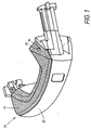
- Fig. 1:
- einen erfindungsgemäßen Türaußengriff in Draufsicht mit geschlossener Blende, perspektivisch
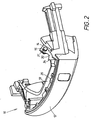
- Fig. 2:
- einen erfindungsgemäßen Türaußengriff bei entfernter Blende, perspektivisch
- Fig. 3a:
- eine Detailansicht der Schraubverbindung bei entfernter Blende mit metallischer Zunge, perspektivisch
- Fig. 3b:
- eine Detailansicht der Schraubverbindung bei entfernter Blende mit metallischem Draht, perspektivisch
- Fig. 4:
- einen erfindungsgemäßen Türaußengriff bei entfernter Blende in Draufsicht
- Fig. 5:
- eine Detailansicht des Anschlusses der metallischen Zunge an das Massepotential des Fahrzeugs bei entfernter Blende in Draufsicht.
- Fig. 1:
- an outside door handle according to the invention in plan view with closed aperture, in perspective
- Fig. 2:
- an outside door handle according to the invention with the panel removed, in perspective
- Fig. 3a:
- a detailed view of the screw with remote aperture with metallic tongue, in perspective
- 3b:
- a detailed view of the screw with remote aperture with metallic wire, in perspective
- 4:
- an outside door handle according to the invention with the panel removed in plan view
- Fig. 5:
- a detailed view of the terminal of the metallic tongue to the ground potential of the vehicle with the diaphragm removed in plan view.
Der in Fig. 1 dargestellte Türaußengriff 10 besteht aus einer elektrisch leitfähigen Blende 11 und einem Griffrest 12. Diese beiden Teile werden durch ein Verbindungsmittel 14 miteinander verbunden. Hierbei besteht die Blende 11 häufig aus Chrom oder verchromtem Material, welches einfach und kostengünstig zu fertigen ist und eine schöne optische Wirkung hat.The
Im aus Fig. 2 ersichtlichen Griffinneren 13 des Türaußengriffes 10 befindet sich ein kapazitiver Sensor 20, der zum Auslösen von Funktionen am Fahrzeug dient. Diese Funktionen können beispielsweise darin bestehen, dass das Fahrzeug selbsttätig öffnet und schließt nachdem die Zugangsberechtigung der den Türaußengriff betätigenden Person festgestellt wurde. Weitere Beispiele sind auch das Hochfahren geöffneter Fenster oder die Einschaltung der Alarmanlage des Fahrzeugs.In the apparent from Fig. 2
Um Störungen der kapazitiven Sensoren 20 zu vermeiden, wird die elektrisch leitfähige Blende 11 an das Massepotential des Fahrzeugs angeschlossen. Der Anschluss 21 an das Massepotential befindet sich im Inneren 13 des Türaußengriffes 10. Diese Verbindung der elektrisch leitfähigen Blende 11 mit dem Anschluss 21 des Massepotentials wird über einen elektrischen Leiter 30 und eine Schraube 15 realisiert, welche auch gleichzeitig das Verbindungsmittel 14 der Blende 11 mit dem Griffrest 12 darstellt.In order to avoid disturbances of the
Ein elektrischer Leiter 30 ist mit seinem einen Ende 31 über die Schraube 15 mit der Blende 11 verbunden, während das andere Ende 32 des Leiters 30 an den im Griffinneren 13 sich befindenden Anschluss 21 des Massepotentials des Fahrzeuges angeschlossen ist. Dieser Leiter 30 verbindet so auf einfache und kostengünstige Weise die Blende 11 mit dem Massepotential des Fahrzeuges.An
In dem in Fig. 3a dargestellten Ausführungsbeispiel ist der elektrische Leiter 30 als metallische Zunge 34 ausgeführt. Diese weist ein Loch 35 auf, durch welches die Schraube 15 geführt wird. Vorteilhafterweise ist das Loch 35 am Ende 31 der metallischen Zunge 34 als Tellerfeder 36 ausgeführt. Die Tellerfeder 36 wird durch Aufbördeln des Innenrandes 37 um das Loch 35 herum erzeugt. Wird nun durch das Festziehen der Schraube 15 eine Klemmpressung 16 erzeugt, so ist diese durch die spezielle Ausführung der metallischen Zunge 34 besonders gesichert. Die Tellerfeder 36 verhindert nämlich das Lösen der Schraube 15 und verstärkt die Klemmpressung 16. Da sowohl die Blende 11 als auch der Griffrest 12 häufig aus Kunststoff hergestellt werden, welcher mit der Zeit zu fließen anfangen kann, sichert die Tellerfeder 36 zusätzlich die Verbindung zwischen der Blende 11 und dem Griffrest 12, so dass auch bei einer fließenden Verformung dieser beiden Teile eine Verbindung sichergestellt ist.In the embodiment shown in Fig. 3a, the
Eine alternative Ausführungsform ist in Fig. 3b dargestellt. Hier ist der elektrische Leiter 30 ein metallischer Draht 33, der durch die Schraube 15 geklemmt wird. Der metallische Draht 33 kann an seinem einen Ende 31 auch eine ring- oder ringsektorartige Ausbildung haben, durch die die Schraube 15 geführt wird. Hierdurch kommt eine bessere Klemmung des metallischen Drahtes 33 zustande.An alternative embodiment is shown in Fig. 3b. Here, the
Um eine Korrosion an der Blende 11 und/oder dem elektrischen Leiter 30 zu vermeiden empfiehlt es sich, den Leiter 30 aus einem nicht rostenden Blech bzw. Draht herzustellen, dessen Potential der elektrochemischen Spannungsreihe nahe dem Potential des Materials ist, aus dem die Blende 11 besteht. Bei einer Korrosion des Leiters 30 könnte nämlich das Bestehen der elektrischen Verbindung zwischen der Blende 11 und dem Anschluss 21 des Massepotentials des Fahrzeuges nicht mehr sichergestellt werden. Eine Korrosion an der Blende 11 würde darüber hinaus noch zu einem unschönen Aussehen führen, was die Attraktivität des Fahrzeuges beeinträchtigt.In order to avoid corrosion on the
In einem bevorzugten Ausführungsbeispiel ist der Leiter 30 an eine im Griffinneren 13 sich befindende Folie 22 angeschlossen, welche ihrerseits mit dem Massepotential des Fahrzeugs verbunden ist. Eine solche Folie 22 ist platzsparend und einfach zu montieren. Günstigerweise wird der Leiter 30 an seinem anderen Ende 32 mit dem Anschluss 21 des Massepotentials, bzw. mit der Folie 22, verlötet. Diese Art des Anschlusses stellt eine leitende Verbindung sicher, die einfach zu realisieren ist und keine zusätzlichen Befestigungsmittel wie Schrauben, Nieten oder ähnliches benötigt. Um das Material des Leiters 30 lötbar zu machen, ist in einigen Ausführungsbeispielen eine vorherige zumindest teilweise Beschichtung des Leiters 30 mit Zinn vorteilhaft.In a preferred embodiment, the
In einer weiteren bevorzugten Ausführungsform wird das Griffinnere 13 des Türaußengriffs 10 von seinem bestimmungsgemäßen Gebrauch zumindest bereichsweise mit einem Füllmaterial ausgefüllt, um die Elektronik 20 vor Feuchtigkeit und Umwelteinflüssen zu schützen.In a further preferred embodiment, the
Um eine Korrosion der Verbindungsstelle zwischen dem metallischen Leiter 30 und dem Anschluss 21 an das Massepotential des Fahrzeugs zu vermeiden, empfiehlt es sich diese Verbindungsstelle innerhalb des mit Füllmaterial ausgefüllten Bereiches anzuordnen. Da hierdurch ein Kontakt mit Feuchtigkeit vermieden wird, ist die Gefahr der Bildung eines galvanischen Elementes gebannt und es muss bei der Werkstoffauswahl nicht in besonderer Weise auf die Potentiale in der elektrochemischen Spannungsreihe eingegangen werden.In order to avoid corrosion of the junction between the
Die hier dargestellten Ausführungsformen stellen lediglich beispielsweise Verwirklichungen der Erfindung dar. Diese ist nicht darauf beschränkt, sondern es sind vielmehr verschiedenste Abwandlungen und Ausführungen möglich. So ist es beispielsweise denkbar, den Griffrest direkt mit einer Ausformung zu versehen, die den Anschluss an des Massepotential des Fahrzeugs darstellt oder des Anschluss an das Massepotential dergestalt auszubilden, dass die Blende direkt über die Schraube angeschlossen werden kann, ohne die Verwendung eines elektrischen Leiters. Weiterhin sind auch noch andere Ausführungen des elektrischen Leiters denkbar. Das eine Ende des Leiters kann verschiedenste Formen aufweisen, beispielsweise einen Halb- oder Teilring ausbilden und / oder mit Blattfedern versehen sein.The embodiments shown here merely represent, for example, realizations of the invention. This is not limited thereto, but rather various modifications and designs are possible. So it is conceivable, for example, to provide the handle remainder directly with a shape that represents the connection to the ground potential of the vehicle or the connection to the ground potential in such a way that the aperture can be connected directly via the screw, without the use of an electrical conductor , Furthermore, other embodiments of the electrical conductor are conceivable. The one end of the conductor may have various shapes, for example, form a half or partial ring and / or be provided with leaf springs.
- 1010
- TüraußengriffOutside door handle
- 1111
- Blendecover
- 1212
- Griffresthandle rest
- 1313
- Griffinnereshandle affairs
- 1414
- Verbindungsmittelconnecting means
- 1515
- Schraubescrew
- 1616
- Klemmpressungclamping pressure
- 2020
- Kapazitiver SensorCapacitive sensor
- 2121
- Anschluss an das MassepotentialConnection to the ground potential
- 2222
- Foliefoil
- 3030
- Elektrischer LeiterElectrical conductor
- 3131
- Eines Ende von 30One end of 30
- 3232
- Anderes Ende von 30Other end of 30
- 3333
- Metallischer DrahtMetallic wire
- 3434
- Metallische ZungeMetallic tongue
- 3535
- Lochhole
- 3636
- TellerfederBelleville spring
- 3737
- Innenrand von 36Inner edge of 36
- 3838
- Umbördelungbeading
Claims (13)
- External door handle (10) for motor vehicles, having at least one capacitive sensor (20) for initiating functions on the vehicle, the handle (10) being partly provided with an electrically conductive shield (11),
and furthermore consisting of a remaining handle section (12) which is connected to the shield (11) via connecting means (14),
and further comprising a handle interior (13), while in the handle interior (13) is a connection (21) to the earth potential of the vehicle,
characterised in that
the connecting means (14) between the shield (11) and remaining handle section (12) is a screw (15),
and in that the screw (15) generates a clamping pressure (16) which connects the shield (11) to the connection (21) to the earth potential. - External door handle according to claim 1, characterised in that an electrical lead (30) is connected at one end (31) to the shield (11) via the screw (15),
while the other end (32) of the lead (30) is connected to the connector (21) of the earth potential. - External door handle according to claim 2, characterised in that the lead (30) consists of a metal wire (33).
- External door handle according to claim 2, characterised in that the lead (30) is in the form of a metal tongue (34).
- External door handle according to one of claims 3 or 4, characterised in that the lead (30) comprises or forms a hole (35) through which the screw (15) is passed.
- External door handle according to one of claims 4 or 5, characterised in that, at its end (31) in contact with the shield (11), the tongue (34) forms a plate spring (36) through which the screw (15) is passed.
- External door handle according to one of claims 1 to 6, characterised in that the shield (11) consists of chromium or chromium-plated material.
- External door handle according to one of claims 2 to 7, characterised in that the lead (30) consists of a rustproof sheet metal whose electrochemical series potential is similar to the potential of the material from which the shield (11) is made.
- External door handle according to one of claims 1 to 8, characterised in that the lead (30) is attached, in the handle interior (13), to a foil (22) which is in turn connected to the earth potential of the vehicle.
- External door handle according to one of claims 1 to 9, characterised in that the lead (30) is attached to the connection (21) to the earth potential by soldering.
- External door handle according to claim 10, characterised in that the material of the lead (30) is made suitable for soldering by at least partially plating it with tin.
- External door handle according to one of claims 1 to 11, characterised in that the interior (13) of the external door handle (10) is at least partly filled with a filling material before being used for its intended purpose.
- External door handle according to claim 12, characterised in that the other end (32) of the lead (30), which is attached to the connection (21) to the earth potential, is within the area filled with filling material.
Priority Applications (2)
| Application Number | Priority Date | Filing Date | Title |
|---|---|---|---|
| DE50302366T DE50302366D1 (en) | 2003-08-29 | 2003-08-29 | Door Handle |
| EP20030019060 EP1518981B1 (en) | 2003-08-29 | 2003-08-29 | External door handle |
Applications Claiming Priority (1)
| Application Number | Priority Date | Filing Date | Title |
|---|---|---|---|
| EP20030019060 EP1518981B1 (en) | 2003-08-29 | 2003-08-29 | External door handle |
Publications (2)
| Publication Number | Publication Date |
|---|---|
| EP1518981A1 EP1518981A1 (en) | 2005-03-30 |
| EP1518981B1 true EP1518981B1 (en) | 2006-02-08 |
Family
ID=34178392
Family Applications (1)
| Application Number | Title | Priority Date | Filing Date |
|---|---|---|---|
| EP20030019060 Expired - Fee Related EP1518981B1 (en) | 2003-08-29 | 2003-08-29 | External door handle |
Country Status (2)
| Country | Link |
|---|---|
| EP (1) | EP1518981B1 (en) |
| DE (1) | DE50302366D1 (en) |
Families Citing this family (5)
| Publication number | Priority date | Publication date | Assignee | Title |
|---|---|---|---|---|
| DE102005031454A1 (en) * | 2005-07-04 | 2007-01-11 | Huf Hülsbeck & Fürst Gmbh & Co. Kg | Door handle, door handle housing and method of making the door handle housing |
| DE102006055100A1 (en) * | 2006-11-21 | 2008-05-29 | Kiekert Ag | Door handle for motor vehicle, has base and screen forming space for accommodation of support for electronic component part, and self-supporting connection provided between support and screen, where screen and base form clip connection |
| IT1392399B1 (en) * | 2008-12-22 | 2012-03-02 | Valeo Spa | HANDLE FOR CAR DOORS |
| DE102014107977A1 (en) * | 2014-06-05 | 2015-12-17 | Witte Automotive Gmbh | Door handle with sensor |
| DE102021126043A1 (en) | 2021-10-07 | 2023-04-13 | Minebea Mitsumi Inc. | SENSING DEVICE OF A DOOR HANDLE FOR A MOTOR VEHICLE |
Family Cites Families (3)
| Publication number | Priority date | Publication date | Assignee | Title |
|---|---|---|---|---|
| GB8701875D0 (en) * | 1987-01-28 | 1987-03-04 | Rolls Royce Motor Cars | Handle assembly |
| US5340174A (en) * | 1993-04-12 | 1994-08-23 | Chrysler Corporation | Mounting arrangement for vehicle door handle |
| DE10048917A1 (en) * | 2000-10-04 | 2002-04-18 | Huf Huelsbeck & Fuerst Gmbh | Handle for doors and flaps of vehicles comprises a base movably mounted on the door and interacting with a closure when actuated, and a cover mounted on the visible side of the base and secured using a slide during assembly |
-
2003
- 2003-08-29 DE DE50302366T patent/DE50302366D1/en not_active Expired - Lifetime
- 2003-08-29 EP EP20030019060 patent/EP1518981B1/en not_active Expired - Fee Related
Also Published As
| Publication number | Publication date |
|---|---|
| EP1518981A1 (en) | 2005-03-30 |
| DE50302366D1 (en) | 2006-04-20 |
Similar Documents
| Publication | Publication Date | Title |
|---|---|---|
| DE60211173T2 (en) | HANDLE FOR MOTOR VEHICLES | |
| DE102008035634B4 (en) | Safety edge for detection of obstacles and device for detecting obstacles | |
| DE19952247C1 (en) | Electronic flat key for remote operation of lock or central locking system has electronic circuit contained between cooperating half shells of grip part housing and enclosed by non-conductive frame | |
| DE19654956B4 (en) | Motor vehicle door | |
| EP2118411B1 (en) | External handle on doors or hatches of vehicles | |
| EP2795240B1 (en) | Control system for controlling a motorized closure element of a vehicle | |
| DE69925089T2 (en) | Handle for motor vehicle lock | |
| DE19742458C1 (en) | Plastics housing for electric circuit board | |
| DE10226133A1 (en) | Arrangement for a device for recognizing an obstacle in the opening area of a movable closing element of a motor vehicle | |
| EP2059421B1 (en) | Handle | |
| DE102006009998A1 (en) | Motor-actuated component with anti-pinch protection | |
| DE102014107407A1 (en) | Handle assembly for a motor vehicle | |
| EP2010743A1 (en) | Sensor-controlled anti-jamming device and motor vehicle | |
| EP0359797A1 (en) | Anti-jamming device | |
| DE19943986B4 (en) | Locking system, especially for motor vehicles | |
| EP1518981B1 (en) | External door handle | |
| DE19636477C2 (en) | Vehicle antenna device | |
| EP0634550A2 (en) | Rotating fastener | |
| DE3126013A1 (en) | GLASS CERAMIC COOKER | |
| WO2009152801A1 (en) | Exterior door handle | |
| DE202006015541U1 (en) | Door and window frame cylindrical magnetic contact sensor has housing that can be rotated inside hollow screw and is secured by cover and spring ring | |
| DE102016002070A1 (en) | Actuation module for a door and / or flap of a motor vehicle | |
| DE202005011044U1 (en) | Sensor system for a anti-trap device | |
| DE102018008105B4 (en) | Motor vehicle emblem with integrated sensor and cleaning device | |
| DE19745869A1 (en) | Vehicle interior door handle with static electrical charge discharging element for user |
Legal Events
| Date | Code | Title | Description |
|---|---|---|---|
| PUAI | Public reference made under article 153(3) epc to a published international application that has entered the european phase |
Free format text: ORIGINAL CODE: 0009012 |
|
| GRAP | Despatch of communication of intention to grant a patent |
Free format text: ORIGINAL CODE: EPIDOSNIGR1 |
|
| 17P | Request for examination filed |
Effective date: 20040603 |
|
| AK | Designated contracting states |
Kind code of ref document: A1 Designated state(s): AT BE BG CH CY CZ DE DK EE ES FI FR GB GR HU IE IT LI LU MC NL PT RO SE SI SK TR |
|
| AX | Request for extension of the european patent |
Extension state: AL LT LV MK |
|
| GRAS | Grant fee paid |
Free format text: ORIGINAL CODE: EPIDOSNIGR3 |
|
| RIN1 | Information on inventor provided before grant (corrected) |
Inventor name: RAGER, ANGELA Inventor name: ILSCHE, JOCHEN Inventor name: NEUHOFF, STEFAN Inventor name: BLAICH, MICHAEL DR.-ING. Inventor name: GEBER, MICHAEL Inventor name: FREYHOLDT, UWE Inventor name: MUELLER, ULRICH |
|
| RBV | Designated contracting states (corrected) |
Designated state(s): DE FR GB IT |
|
| RAP1 | Party data changed (applicant data changed or rights of an application transferred) |
Owner name: DAIMLERCHRYSLER AG Owner name: HUF HUELSBECK & FUERST GMBH & CO. KG |
|
| AKX | Designation fees paid |
Designated state(s): DE FR GB IT |
|
| GRAA | (expected) grant |
Free format text: ORIGINAL CODE: 0009210 |
|
| AK | Designated contracting states |
Kind code of ref document: B1 Designated state(s): DE FR GB IT |
|
| REG | Reference to a national code |
Ref country code: GB Ref legal event code: FG4D Free format text: NOT ENGLISH |
|
| REF | Corresponds to: |
Ref document number: 50302366 Country of ref document: DE Date of ref document: 20060420 Kind code of ref document: P |
|
| GBT | Gb: translation of ep patent filed (gb section 77(6)(a)/1977) |
Effective date: 20060524 |
|
| ET | Fr: translation filed | ||
| PLBE | No opposition filed within time limit |
Free format text: ORIGINAL CODE: 0009261 |
|
| STAA | Information on the status of an ep patent application or granted ep patent |
Free format text: STATUS: NO OPPOSITION FILED WITHIN TIME LIMIT |
|
| 26N | No opposition filed |
Effective date: 20061109 |
|
| PGFP | Annual fee paid to national office [announced via postgrant information from national office to epo] |
Ref country code: GB Payment date: 20140826 Year of fee payment: 12 |
|
| PGFP | Annual fee paid to national office [announced via postgrant information from national office to epo] |
Ref country code: IT Payment date: 20140805 Year of fee payment: 12 |
|
| REG | Reference to a national code |
Ref country code: FR Ref legal event code: PLFP Year of fee payment: 13 |
|
| GBPC | Gb: european patent ceased through non-payment of renewal fee |
Effective date: 20150829 |
|
| PG25 | Lapsed in a contracting state [announced via postgrant information from national office to epo] |
Ref country code: IT Free format text: LAPSE BECAUSE OF NON-PAYMENT OF DUE FEES Effective date: 20150829 |
|
| PG25 | Lapsed in a contracting state [announced via postgrant information from national office to epo] |
Ref country code: GB Free format text: LAPSE BECAUSE OF NON-PAYMENT OF DUE FEES Effective date: 20150829 |
|
| REG | Reference to a national code |
Ref country code: FR Ref legal event code: PLFP Year of fee payment: 14 |
|
| REG | Reference to a national code |
Ref country code: FR Ref legal event code: PLFP Year of fee payment: 15 |
|
| REG | Reference to a national code |
Ref country code: FR Ref legal event code: PLFP Year of fee payment: 16 |
|
| PGFP | Annual fee paid to national office [announced via postgrant information from national office to epo] |
Ref country code: FR Payment date: 20200826 Year of fee payment: 18 |
|
| PGFP | Annual fee paid to national office [announced via postgrant information from national office to epo] |
Ref country code: DE Payment date: 20210728 Year of fee payment: 19 |
|
| PG25 | Lapsed in a contracting state [announced via postgrant information from national office to epo] |
Ref country code: FR Free format text: LAPSE BECAUSE OF NON-PAYMENT OF DUE FEES Effective date: 20210831 |
|
| REG | Reference to a national code |
Ref country code: DE Ref legal event code: R119 Ref document number: 50302366 Country of ref document: DE |
|
| PG25 | Lapsed in a contracting state [announced via postgrant information from national office to epo] |
Ref country code: DE Free format text: LAPSE BECAUSE OF NON-PAYMENT OF DUE FEES Effective date: 20230301 |