EP1518756A1 - Elektroakustische Wandlereinheit für eine Freisprecheinrichtung - Google Patents
Elektroakustische Wandlereinheit für eine Freisprecheinrichtung Download PDFInfo
- Publication number
- EP1518756A1 EP1518756A1 EP04022881A EP04022881A EP1518756A1 EP 1518756 A1 EP1518756 A1 EP 1518756A1 EP 04022881 A EP04022881 A EP 04022881A EP 04022881 A EP04022881 A EP 04022881A EP 1518756 A1 EP1518756 A1 EP 1518756A1
- Authority
- EP
- European Patent Office
- Prior art keywords
- transducer unit
- unit according
- electroacoustic transducer
- sound
- arm
- Prior art date
- Legal status (The legal status is an assumption and is not a legal conclusion. Google has not performed a legal analysis and makes no representation as to the accuracy of the status listed.)
- Granted
Links
Images

Classifications
-
- H—ELECTRICITY
- H04—ELECTRIC COMMUNICATION TECHNIQUE
- H04R—LOUDSPEAKERS, MICROPHONES, GRAMOPHONE PICK-UPS OR LIKE ACOUSTIC ELECTROMECHANICAL TRANSDUCERS; ELECTRIC HEARING AIDS; PUBLIC ADDRESS SYSTEMS
- H04R1/00—Details of transducers, loudspeakers or microphones
- H04R1/08—Mouthpieces; Microphones; Attachments therefor
- H04R1/083—Special constructions of mouthpieces
Definitions
- the invention relates to an electroacoustic transducer unit for a hands-free device according to the preamble of claim 1.
- a generic electro-acoustic transducer unit preferably with a speaker for a handsfree of a mobile phone in one Automobile, which is attachable in the upper backrest area, goes, for example from EP 0 917 988 A1.
- This converter unit is between a Seat back and a headrest on or between two headrest supports attached. The attachment takes place, for example, as an entrapment between the headrest supports by a longitudinal suspension or a Searchnver Surgi a part of the converter unit.
- Problematic with this transducer unit is the arrangement of the speaker between the both headrest supports.
- Electroacoustic transducer units where speakers in the headrest a seat and a microphone on a support attached to the headrest are arranged, go further from JP 11-113080 and EP 0 715 575 B1.
- the DE 100 43 918 A1 discloses a vehicle speakerphone device in which both the Speaker as well as the microphone at the top of a rear seatback are arranged.
- the speaker is behind the head a person sitting on the seat. This arrangement of the speaker leads to an unfavorable sound transmission.
- a handsfree telephone devices resulting in at least one preferably adjustable by means of a drive Audio device has a speaker and a microphone.
- the listening device can be arranged on the side of a headrest of a vehicle seat be in a swing-out front element at one Position a microphone and integrated in another position a speaker are.
- the listening device lays down like a listener in this way to the ear of a user, so that for other passengers of the vehicle listening to the speaker playback is not possible.
- This speakerphone has a complex structure with two pivot joints particularly with regard to vibrations prevailing in a vehicle, Vibrations and the like to an unfavorable sound transmission behavior can lead.
- the distance between the speaker and the Microphone fixed and so not on different head dimensions of a Person adjustable.
- the microphone is located on this speakerphone By design, aside from the head, and can not in front of the Mouth be swung. Even in the case of an accident, this device problematic, since the rigidly trained listening device by a vehicle crash Can cause injury to the head.
- U1 is furthermore a hands-free device for a mobile phone known in a motor vehicle, with a tubular bifurcated Holder whose first end is firmly connected to a mounting arrangement is and has a second and third end, with an earphone am second end of the tubular forked bracket is attached and a Microphone is attached to the third end of the tubular forked bracket.
- the hands-free device is attached to a headrest support of a motor vehicle seat attached. Even with this speakerphone is the distance between microphone and earphone fixed and therefore not on the Head dimensions of different persons adjustable.
- the tubular holder an adverse structure-borne sound transmission from Speaker to the microphone.
- the attachment of the handsfree by means of a single flexible bracket on the headrest support can finally also to adverse vibrations of the entire speakerphone Cause vibrations.
- the invention is based on the object in an electro-acoustic Transducer unit for a handsfree of a vehicle the acoustic To improve transmission behavior to the effect that in particular the noise nuisance for other persons as well as the transmission of disturbing driving and vehicle noise minimizes and at the same time the Speech intelligibility can be improved. Furthermore, the risk of accidents, the From such a converter unit emanating minimized.
- a deformable, in particular elastically designed swivel arm, on which at least one sound transmission means is arranged, and through a flexible arm disposed on the pivoting arm, on which at least a sound receiving means is arranged can by variations of the spatial Arrangement of microphone and sound outlet the functionality of a telephone be simulated very advantageous.
- the arrangement of the sound receiving means on a flexible arm, for example on a so-called Gooseneck is an accurate alignment of the sound pickup on the mouth of a person and so optimal sound transmission allows.
- the deformable, in particular elastically formed swivel arm reduced In addition, the risk of injury in the event of an accident.
- the swivel arm is attached to a holding arrangement arranged when used in a vehicle in turn for example, on the headrest, on the seat back or on a body part of the vehicle is attached.
- the arrangement of electro-acoustic transducer unit on the headrest has the great advantage an automatic height adjustment for different body sizes of the handsfree using people on.
- arm becomes the influence of external vibrations and reduces vibration on the microphone.
- the pivot arm has a longitudinally displaceable Swivel axis on. This advantageously allows not only the angular arrangement of the swing arm, but also the adjustment of the distance the sound transmission means and the sound receiving means of the Attachment point of the converter unit, for example on a headrest of a vehicle.
- the sound transmission means may, for example, at least one in or on be arranged the swivel arm speaker.
- the at least one sound transmission means at least one sound outlet at least one arranged in the pivot arm sound guide channel is arranged with at least one in or on the holding device Speaker is schal facedd connected.
- the speaker separated from the sound outlet.
- the Sound duct with at least one arranged in or on the pivot arm Speaker is schal facedd connected.
- the Speaker component of the swivel arm is schal facedd connected.
- the sound outlet is to avoid contamination advantageously covered with an acoustically permeable material.
- This material may be, for example, a foam, a grid or a fabric.
- the sound receiving means is preferably a microphone. It can be pure In principle, microphones without directivity are used. advantageously, However, microphones are used with directivity, due to the flexible arm can be optimally aligned to the mouth of a person.
- the swivel arm with the holding device both electrically and mechanically releasable, for example, connected by plug or the like is advantageously provided.
- the swivel arm on the holding device so fasten that in any angular positions and with any longitudinal direction shifted pivot axis can be locked.
- the pivot arm on the holding device in predetermined Positions that are also adapted to standard body measurements of persons, can be arranged.
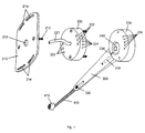
- the vehicle shown in FIGS. 1 and 2 includes one on a headrest 100 of a vehicle (not shown) arranged holding plate 210 at a housing element 220 can be fastened.
- the attachment of the retaining plate 210 takes place for example by screw 217 over in the holding plate 210 provided curved slots 214, the attachment in the Allow angles to the vertical of the holding plate 210 on the headrest 100.
- a further housing element 230 is arranged on the housing element 220.
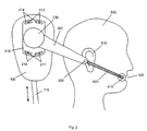
- the housing member 220 may be on the holding plate 210 in different Angular positions are arranged and so on the dimensions of a Head 500 of a person, in particular adapted to the ear 510 of this person become.
- angularly offset for example, provided with threads Bores 222 disposed in the housing member 220, in the on the retaining plate provided screws 212 engage.
- a speaker 240 is arranged, for example.
- the housing element 220, as well as in the housing member 230 may further Circuit arrangements, such as preamplifiers, equalizers, signal processing Circuits or the like (not shown) may be arranged.
- an elastically formed Swivel arm 300 Firmly connected to the further housing part 230 is an elastically formed Swivel arm 300.
- the elastic swing arm 300 is a sound guide channel 310 arranged, the schall facedd with the speaker 240 connected is.
- the acoustic signals emitted by the loudspeaker be through the sound guide channel 310 to a sound outlet 320 transmitted, which is located adjacent to the person's ear 510 (Fig. 2).
- the sound outlet 320 is acoustically, for example permeable material, such as a foam, a grid or Covered a tissue, so as to prevent the ingress of dirt in the Sound conduction channel 310 to prevent.
- a pressure equalization port 236 is used to unfavorable pressure conditions of the built-in speaker 240 to avoid.
- the elastically formed pivot arm 300 is followed by a flexible one Arm 400, which at its front end a sound receiving means in the form a microphone 410 carries.
- a flexibly formed arm 400 for example a gooseneck, the microphone 410 in a respect the sound transmission behavior favorable position in front of the mouth 520 the person are arranged (Fig. 2).
- this flexible arm 400 can so in particular microphones with directivity advantageously used and be positioned.
- the pivoting arm 300 may have an axis 350 as shown in FIG. which is longitudinally displaceable in the directions indicated in Fig. 3 with A. He is also along the direction indicated by double arrow W directions pivotable and adaptable to different spatial positions.
- the microphone 410 is by means of the flexible, for example as a gooseneck twisted arms 400 along the directions labeled P positionable.
- the flexible for example as a gooseneck twisted arms 400 along the directions labeled P positionable.
- instead of just one Sound outlet 320 may be provided a plurality of sound outlet, some of which are closable, for example, by blind plugs 321, 322. This allows an optimal spatial arrangement of the unlocked Sound outlet 320 relative to the ear of a person without the Swivel arm 300 adjusted, for example, rotated or moved got to.
- the pivot arm 300, the housing parts 220, 230 and the holding plate 210th can, as shown in Fig. 1, consist of separate parts, but also be formed wholly or partially in one piece.
- the sound conduction through the sound guide channel 310 in the pivot arm and the arrangement of the speaker 240 in the housing part 230 is not advantageous only with regard to an improved visual appearance.
- This arrangement also significantly reduces the risk of accidents, as the speaker, which regularly has a larger and heavier design than for example, the microphone 410 is not located near the ear and so on do not contribute to injuries, for example in a vehicle crash can.
- the microphone 410 is disposed on the flexible arm 400 and can Dodge in an accident.
- the sound guide channel 310 and the sound outlet 320 can also be provided to arrange a speaker directly near the ear.
- the sound conduction channel 310 instead of the sound conduction channel 310 electrical connecting lines to the speaker inside the deformable elastic trained swivel arm 300. Due to the deformable, elastic training the swing arm 300 is also in this case the risk of injury to rigid arrangements known from the prior art are minimized.
- the arrangement of the microphone 410 on the elastic arm 400 may be the spatial arrangement a microphone and a sound outlet of a telephone receiver with all the benefits in terms of sound transmission quality that a telephone handset has to be simulated. Due to the arrangement of the sound outlet in the immediate Ohmähe arises only a small noise pollution of others People. In addition, there is only a small risk of feedback by sufficient distance to the microphone 410. This minimizes in particular the case of handsfree, for example, via speakers in the Vehicle interior are transmitted, resulting Hall effects. hereby is still a very good spatial location of the sound signal and thus an increased speech intelligibility possible.
- the speaker 240 am Housing part 230 by snap-in contact simultaneously mechanical and electrically assembled and disassembled and so also be retrofitted can. Furthermore, it can be provided that the housing part 230 with the housing part 220 and / or the housing part 220 with the mounting plate 210 via contact connections 224, 234, for example, plug contacts or spring contacts, is electrically connected.
- the invisible electrical conduit means for example a cable 227 lead through the pivot arm 300 via the housing elements 230, 220 and 210 directly, for example, through an opening 213 in the holding plate 210 and a corresponding opening in the headrest 100 in the headrest 100 and from there, for example, by a headrest support 110 in the seat back and from this to other electrical equipment of the vehicle.
- the electroacoustic transducer unit is not on the right Side of the headrest, as shown in Fig. 2, must be attached, but can also be arranged on the left side.
- the device can in principle also in the upper seat back area or on a body part of the vehicle, for example be arranged on the B-pillar.
- the holding plate 210 already be factory provided at the seat, so that a retrofit of a prescribed Handsfree is possible at any time.
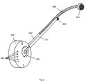
- FIG. 4 In another, shown in Fig. 4 embodiment of an electro-acoustic Converter unit are the same elements with the same reference numerals provided so that with respect to their description to the above reference is taken.
- the swivel arm 300 ' is formed as a very thin tubular member to which the flexible Arm 400, which carries the microphone 410, connects.
- the pivot arm 300 'as the support arm 400 flexible. In this case fall arm 300 'and arm 400 together.
- the sound guide channel 310 ' for example, by a flexible Hose formed on the pivot arm 300 'and optionally the holding arm 400 is attached.
- the above-described electro-acoustic transducer unit for a hands-free device can be used in different vehicles, for example in motor vehicles, commercial vehicles such as lorries, buses, but also in construction machinery, such as excavators, cranes and the like, but also in rail vehicles or in ships or aircraft.
- the handsfree can be in the telephony, or as an announcement system for example, in buses or as an input system for navigation systems with Speech output or for voice-operated communication devices in vehicles, for example for the operation of radios, CD players or other entertainment media in vehicles.
- the handsfree can also be used to play the signals these facilities or systems are used.
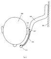
- the electroacoustic transducer unit may also be in any other locations are used, for example, for voice control of a machine. In this case, it can, as shown in Fig. 5, for example, at a Wall 600 or a machine part or the like. Be arranged. In this Trap, the pivot arm 300 "a multi-curved shape, so that the sound exit opening 320 "and the microphone 410 optimally on the ear 510th and the mouth of a person 500 are adapted.
Landscapes
- Physics & Mathematics (AREA)
- Engineering & Computer Science (AREA)
- Acoustics & Sound (AREA)
- Signal Processing (AREA)
- Telephone Set Structure (AREA)
- Fittings On The Vehicle Exterior For Carrying Loads, And Devices For Holding Or Mounting Articles (AREA)
Abstract
Description
- Fig. 1
- eine elektroakustische Wandlereinheit gemäß der Erfindung in Explosionsdarstellung;
- Fig. 2
- die Anordnung der in Fig. 1 dargestellten elektroakustischen Wandlereinheit an einer Kopfstütze eines Fahrzeugs;
- Fig. 3
- ein Ausführungsbeispiel eines Schwenkarms mit einem an diesem angeordneten flexiblen, ein Mikrofon tragenden Arm gemäß der Erfindung ;
- Fig.4
- ein weiteres Ausführungsbeispiel eines Schwenkarms mit einem an diesem angeordneten, ein Mikrofon tragenden flexiblen Arm gemäß der Erfindung und
- Fig. 5
- ein wiederum anderes Ausführungsbeispiel eines Schwenkarms mit einem daran angeordneten, ein Mikrofon tragenden Arm gemäß der Erfindung.
Claims (15)
- Elektroakustische Wandlereinheit für eine Freisprecheinrichtung, wobei die Wandlereinheit zur Anordnung im Kopfbereich ausgebildet ist, gekennzeichnet durch einen verformbar, insbesondere elastisch ausgebildeten Schwenkarm (300; 300'; 300"), an dem wenigstens ein Schallübertragungsmittel angeordnet ist, und durch einen an dem Schwenkarm (300; 300'; 300") angeordneten flexiblen Arm (400), an dem wenigstens ein Schallaufnahmemittel (410) angeordnet ist.
- Elektroakustische Wandlereinheit nach Anspruch 1, dadurch gekennzeichnet, daß der Schwenkarm (300; 300'; 300") an einer Halteeinrichtung (210, 220) lösbar befestigt ist.
- Elektroakustische Wandlereinheit nach Anspruch 1 oder 2, dadurch gekennzeichnet, daß der Schwenkarm (300; 300'; 300") eine in Längsrichtung (A) verschiebliche Schwenkachse (350) aufweist.
- Elektroakustische Wandlereinheit nach einem der vorstehenden Ansprüche, dadurch gekennzeichnet, daß das wenigstens eine Schallübertragungsmittel wenigstens ein in oder an dem Schwenkarm (300; 300'; 300") angeordneter Lautsprecher ist.
- Elektroakustische Wandlereinheit nach einem der Ansprüche 1 bis 3, dadurch gekennzeichnet, daß das wenigstens eine Schallübertragungsmittel wenigstens eine Schallauslaßöffnung (320; 320'; 320") wenigstens eines in oder an dem Schwenkarm (300; 300'; 300") angeordneten Schallführungskanals (310) ist, der mit wenigstens einem in oder an der Halteeinrichtung angeordneten Lautsprecher (240) schalleitend verbunden ist.
- Elektroakustische Wandlereinheit nach einem der Ansprüche 1 bis 3, dadurch gekennzeichnet, daß das wenigstens eine Schallübertragungsmittel wenigstens eine Schallauslaßöffnung (320; 320'; 320") wenigstens eines in oder an dem Schwenkarm (300; 300'; 300") angeordneten Schallführungskanals (310) ist, der mit wenigstens einem in oder an dem Schwenkarm (300; 300'; 300") angeordneten Lautsprecher (240) schalleitend verbunden ist.
- Elektroakustische Wandlereinheit nach Anspruch 5 oder 6, dadurch gekennzeichnet, daß die wenigstens eine Schallauslaßöffnung (320; 320'; 320") mit einem akustisch durchlässigen Material überdeckt ist.
- Elektroakustische Wandlereinheit nach Anspruch 7, dadurch gekennzeichnet, daß das akustisch durchlässige Material ein Schaumstoff, ein Gitter oder ein Gewebe ist.
- Elektroakustische Wandlereinheit nach einem der vorstehenden Ansprüche, dadurch gekennzeichnet, daß mehrere vorzugsweise in Längsrichtung des Schwenkarms (300; 300'; 300") angeordnete Schallauslaßöffnungen (320; 320'; 320") vorgesehen sind, die wenigstens teilweise durch Blindstopfen (321, 322) verschließbar sind.
- Elektroakustische Wandlereinheit nach einem der vorstehenden Ansprüche, dadurch gekennzeichnet, daß das wenigstens eine Schallaufnahmemittel wenigstens ein Mikrofon (410) ist.
- Elektroakustische Wandlereinheit nach Anspruch 10, dadurch gekennzeichnet, daß das wenigstens eine Mikrofon (410) eine Richtwirkung aufweist.
- Elektroakustische Wandlereinheit nach einem der vorstehenden Ansprüche, dadurch gekennzeichnet, daß der Schwenkarm (300; 300'; 300") mit der Halteeinrichtung sowohl elektrisch als auch mechanisch lösbar verbunden ist.
- Elektroakustische Wandlereinheit nach einem der vorstehenden Ansprüche, dadurch gekennzeichnet, daß in der Nähe des Lautsprechers (240), vorzugsweise der wenigstens einen Schallauslaßöffnung (320; 320'; 320") gegenüberliegend, wenigstens eine Druckausgleichsöffnung (236) vorgesehen ist.
- Elektroakustische Wandlereinheit nach einem der vorstehenden Ansprüche, dadurch gekennzeichnet, daß in dem Schwenkarm (300; 300'; 300") und/oder in der Halteeinrichtung elektronische Schaltungen angeordnet sind.
- Elektroakustische Wandlereinheit nach einem der vorstehenden Ansprüche, dadurch gekennzeichnet, daß der Schwenkarm (300; 300'; 300") an der Halteeinrichtung in vorgebbaren Positionen anordenbar ist.
Applications Claiming Priority (4)
| Application Number | Priority Date | Filing Date | Title |
|---|---|---|---|
| DE10344746 | 2003-09-25 | ||
| DE10344746 | 2003-09-25 | ||
| DE10348166A DE10348166A1 (de) | 2003-09-25 | 2003-10-16 | Elektroakustische Wandlereinheit für eine Freisprecheinrichtung |
| DE10348166 | 2003-10-16 |
Publications (2)
| Publication Number | Publication Date |
|---|---|
| EP1518756A1 true EP1518756A1 (de) | 2005-03-30 |
| EP1518756B1 EP1518756B1 (de) | 2008-11-05 |
Family
ID=34195772
Family Applications (1)
| Application Number | Title | Priority Date | Filing Date |
|---|---|---|---|
| EP20040022881 Expired - Lifetime EP1518756B1 (de) | 2003-09-25 | 2004-09-24 | Elektroakustische Wandlereinheit für eine Freisprecheinrichtung |
Country Status (1)
| Country | Link |
|---|---|
| EP (1) | EP1518756B1 (de) |
Cited By (1)
| Publication number | Priority date | Publication date | Assignee | Title |
|---|---|---|---|---|
| CN107071619A (zh) * | 2017-05-02 | 2017-08-18 | 杨小龙 | 一种头枕安装三轴定位旋转式车载蓝牙耳机 |
Citations (8)
| Publication number | Priority date | Publication date | Assignee | Title |
|---|---|---|---|---|
| US4151468A (en) * | 1977-08-25 | 1979-04-24 | Kerr Leslie I | Microphone holder attachment and switch control therefor |
| US4215250A (en) * | 1978-10-18 | 1980-07-29 | Western Electric Company, Inc. | Microphone support with simultaneous adjustment of plural degrees of freedom |
| FR2714875A1 (fr) * | 1994-01-10 | 1995-07-13 | Collet Claude | Insert téléphonique main libre de voiture. |
| US5761298A (en) * | 1996-05-31 | 1998-06-02 | Plantronics, Inc. | Communications headset with universally adaptable receiver and voice transmitter |
| US6097809A (en) * | 1992-09-29 | 2000-08-01 | Unex Corporation | Adjustable telephone headset |
| US6108566A (en) * | 1998-03-23 | 2000-08-22 | Albanese; Thomas J. | Hands-free mobile telephone |
| US6272362B1 (en) * | 1999-06-08 | 2001-08-07 | Chin-Yang Wang | Hand-free handset for use with a cellular telephone in an automobile |
| US20030003969A1 (en) * | 2001-06-29 | 2003-01-02 | Eric Tong | Cellular telephone headset |
-
2004
- 2004-09-24 EP EP20040022881 patent/EP1518756B1/de not_active Expired - Lifetime
Patent Citations (8)
| Publication number | Priority date | Publication date | Assignee | Title |
|---|---|---|---|---|
| US4151468A (en) * | 1977-08-25 | 1979-04-24 | Kerr Leslie I | Microphone holder attachment and switch control therefor |
| US4215250A (en) * | 1978-10-18 | 1980-07-29 | Western Electric Company, Inc. | Microphone support with simultaneous adjustment of plural degrees of freedom |
| US6097809A (en) * | 1992-09-29 | 2000-08-01 | Unex Corporation | Adjustable telephone headset |
| FR2714875A1 (fr) * | 1994-01-10 | 1995-07-13 | Collet Claude | Insert téléphonique main libre de voiture. |
| US5761298A (en) * | 1996-05-31 | 1998-06-02 | Plantronics, Inc. | Communications headset with universally adaptable receiver and voice transmitter |
| US6108566A (en) * | 1998-03-23 | 2000-08-22 | Albanese; Thomas J. | Hands-free mobile telephone |
| US6272362B1 (en) * | 1999-06-08 | 2001-08-07 | Chin-Yang Wang | Hand-free handset for use with a cellular telephone in an automobile |
| US20030003969A1 (en) * | 2001-06-29 | 2003-01-02 | Eric Tong | Cellular telephone headset |
Cited By (1)
| Publication number | Priority date | Publication date | Assignee | Title |
|---|---|---|---|---|
| CN107071619A (zh) * | 2017-05-02 | 2017-08-18 | 杨小龙 | 一种头枕安装三轴定位旋转式车载蓝牙耳机 |
Also Published As
| Publication number | Publication date |
|---|---|
| EP1518756B1 (de) | 2008-11-05 |
Similar Documents
| Publication | Publication Date | Title |
|---|---|---|
| DE69414579T2 (de) | Vorrichtung für mobiltelefone | |
| EP0917988B1 (de) | Elektroakustische Wandlereinheit | |
| DE19942858C2 (de) | Sitzplatzbezogene Beschallungseinrichtung | |
| EP1652729B1 (de) | Modularer Geräteträger mit Mehrzweck-Zwischenbaubox für Kleincomputer, Handys und dergleichen | |
| DE19840444A1 (de) | Kopfstütze, die mit mindestens einem Lautsprecher versehen ist, Fahrzeugsitz, der eine solche Kopfstütze umfasst, und Audioeinheit, die eine solche Kopfstütze einschließt | |
| DE10033985A1 (de) | Freisprechmikrofonhalterung | |
| WO2021116301A1 (de) | Rückenlehne für einen fahrzeugsitz | |
| DE29909964U1 (de) | Freisprecheinrichtung | |
| EP1053912B1 (de) | Armaturenbrett mit integriertem Richtmikrofon | |
| EP1172258B1 (de) | Freisprechanordnung | |
| EP0659029B1 (de) | Einrichtung zum Umschalten eines Lautsprechers | |
| EP1518756B1 (de) | Elektroakustische Wandlereinheit für eine Freisprecheinrichtung | |
| DE20315890U1 (de) | Elektroakustische Wandlereinheit für eine Freisprecheinrichtung | |
| DE2449193A1 (de) | Sitz mit kopf- oder nackenstuetze, insbesondere fuer fahrzeuge | |
| DE60201642T2 (de) | Freisprechvorrichtung für Fahrzeugkopfstütze und Verwendungsverfahren | |
| DE19744603B4 (de) | Kopfstütze für ein Kraftfahrzeug | |
| DE102006004198B4 (de) | Freisprecheinrichtung auf Sicherheitsgurt | |
| DE10013432C1 (de) | Mikrofonanordnung | |
| DE10024400A1 (de) | Vorrichtung zur Erfassung von Schallwellen in einem Fahrzeug | |
| DE102018125515A1 (de) | Lärmkompensationsvorrichtung zur Verwendung in einem Kraftfahrzeug | |
| DE19544152C1 (de) | Elektroakustische Übertragungsanlage mit Prüfeinrichtung | |
| DE10105513A1 (de) | Freisprecheinrichtung | |
| DE19959744C2 (de) | Halterung zur lösbaren Befestigung eines Mobiltelefons oder eines Handgeräts einer fest installierten Telefonanlage in einem Fahrzeug | |
| EP1202537A2 (de) | Freisprecheinrichtung | |
| DE102006016593A1 (de) | Kommunikationseinrichtung für Fahrzeuge |
Legal Events
| Date | Code | Title | Description |
|---|---|---|---|
| PUAI | Public reference made under article 153(3) epc to a published international application that has entered the european phase |
Free format text: ORIGINAL CODE: 0009012 |
|
| AK | Designated contracting states |
Kind code of ref document: A1 Designated state(s): AT BE BG CH CY CZ DE DK EE ES FI FR GB GR HU IE IT LI LU MC NL PL PT RO SE SI SK TR |
|
| AX | Request for extension of the european patent |
Extension state: AL HR LT LV MK |
|
| RIN1 | Information on inventor provided before grant (corrected) |
Inventor name: WENNINGER, JOCHEN Inventor name: WEIDEMANN, GUNTER |
|
| 17P | Request for examination filed |
Effective date: 20050704 |
|
| AKX | Designation fees paid |
Designated state(s): BE DE ES FR NL |
|
| GRAP | Despatch of communication of intention to grant a patent |
Free format text: ORIGINAL CODE: EPIDOSNIGR1 |
|
| GRAS | Grant fee paid |
Free format text: ORIGINAL CODE: EPIDOSNIGR3 |
|
| GRAA | (expected) grant |
Free format text: ORIGINAL CODE: 0009210 |
|
| AK | Designated contracting states |
Kind code of ref document: B1 Designated state(s): BE DE ES FR NL |
|
| REF | Corresponds to: |
Ref document number: 502004008390 Country of ref document: DE Date of ref document: 20081218 Kind code of ref document: P |
|
| PG25 | Lapsed in a contracting state [announced via postgrant information from national office to epo] |
Ref country code: ES Free format text: LAPSE BECAUSE OF FAILURE TO SUBMIT A TRANSLATION OF THE DESCRIPTION OR TO PAY THE FEE WITHIN THE PRESCRIBED TIME-LIMIT Effective date: 20090216 |
|
| PLBE | No opposition filed within time limit |
Free format text: ORIGINAL CODE: 0009261 |
|
| STAA | Information on the status of an ep patent application or granted ep patent |
Free format text: STATUS: NO OPPOSITION FILED WITHIN TIME LIMIT |
|
| 26N | No opposition filed |
Effective date: 20090806 |
|
| BERE | Be: lapsed |
Owner name: BEYERDYNAMIC G.M.B.H. & CO. Effective date: 20090930 |
|
| REG | Reference to a national code |
Ref country code: FR Ref legal event code: ST Effective date: 20100531 |
|
| PG25 | Lapsed in a contracting state [announced via postgrant information from national office to epo] |
Ref country code: FR Free format text: LAPSE BECAUSE OF NON-PAYMENT OF DUE FEES Effective date: 20090930 |
|
| PG25 | Lapsed in a contracting state [announced via postgrant information from national office to epo] |
Ref country code: BE Free format text: LAPSE BECAUSE OF NON-PAYMENT OF DUE FEES Effective date: 20090930 |
|
| PGFP | Annual fee paid to national office [announced via postgrant information from national office to epo] |
Ref country code: DE Payment date: 20170920 Year of fee payment: 14 |
|
| PGFP | Annual fee paid to national office [announced via postgrant information from national office to epo] |
Ref country code: NL Payment date: 20170925 Year of fee payment: 14 |
|
| REG | Reference to a national code |
Ref country code: DE Ref legal event code: R119 Ref document number: 502004008390 Country of ref document: DE |
|
| REG | Reference to a national code |
Ref country code: NL Ref legal event code: MM Effective date: 20181001 |
|
| PG25 | Lapsed in a contracting state [announced via postgrant information from national office to epo] |
Ref country code: NL Free format text: LAPSE BECAUSE OF NON-PAYMENT OF DUE FEES Effective date: 20181001 |
|
| PG25 | Lapsed in a contracting state [announced via postgrant information from national office to epo] |
Ref country code: DE Free format text: LAPSE BECAUSE OF NON-PAYMENT OF DUE FEES Effective date: 20190402 |