EP1518753A2 - Structure de levier d'actionnement - Google Patents
Structure de levier d'actionnement Download PDFInfo
- Publication number
- EP1518753A2 EP1518753A2 EP04022132A EP04022132A EP1518753A2 EP 1518753 A2 EP1518753 A2 EP 1518753A2 EP 04022132 A EP04022132 A EP 04022132A EP 04022132 A EP04022132 A EP 04022132A EP 1518753 A2 EP1518753 A2 EP 1518753A2
- Authority
- EP
- European Patent Office
- Prior art keywords
- operation lever
- arm
- lever
- main body
- hollow section
- Prior art date
- Legal status (The legal status is an assumption and is not a legal conclusion. Google has not performed a legal analysis and makes no representation as to the accuracy of the status listed.)
- Withdrawn
Links
Images


Classifications
-
- B—PERFORMING OPERATIONS; TRANSPORTING
- B60—VEHICLES IN GENERAL
- B60Q—ARRANGEMENT OF SIGNALLING OR LIGHTING DEVICES, THE MOUNTING OR SUPPORTING THEREOF OR CIRCUITS THEREFOR, FOR VEHICLES IN GENERAL
- B60Q1/00—Arrangement of optical signalling or lighting devices, the mounting or supporting thereof or circuits therefor
- B60Q1/02—Arrangement of optical signalling or lighting devices, the mounting or supporting thereof or circuits therefor the devices being primarily intended to illuminate the way ahead or to illuminate other areas of way or environments
- B60Q1/04—Arrangement of optical signalling or lighting devices, the mounting or supporting thereof or circuits therefor the devices being primarily intended to illuminate the way ahead or to illuminate other areas of way or environments the devices being headlights
- B60Q1/14—Arrangement of optical signalling or lighting devices, the mounting or supporting thereof or circuits therefor the devices being primarily intended to illuminate the way ahead or to illuminate other areas of way or environments the devices being headlights having dimming means
- B60Q1/1446—Arrangement of optical signalling or lighting devices, the mounting or supporting thereof or circuits therefor the devices being primarily intended to illuminate the way ahead or to illuminate other areas of way or environments the devices being headlights having dimming means controlled by mechanically actuated switches
- B60Q1/1453—Hand actuated switches
- B60Q1/1461—Multifunction switches for dimming headlights and controlling additional devices, e.g. for controlling direction indicating lights
- B60Q1/1469—Multifunction switches for dimming headlights and controlling additional devices, e.g. for controlling direction indicating lights controlled by or attached to a single lever, e.g. steering column stalk switches
-
- Y—GENERAL TAGGING OF NEW TECHNOLOGICAL DEVELOPMENTS; GENERAL TAGGING OF CROSS-SECTIONAL TECHNOLOGIES SPANNING OVER SEVERAL SECTIONS OF THE IPC; TECHNICAL SUBJECTS COVERED BY FORMER USPC CROSS-REFERENCE ART COLLECTIONS [XRACs] AND DIGESTS
- Y10—TECHNICAL SUBJECTS COVERED BY FORMER USPC
- Y10T—TECHNICAL SUBJECTS COVERED BY FORMER US CLASSIFICATION
- Y10T74/00—Machine element or mechanism
- Y10T74/20—Control lever and linkage systems
- Y10T74/20576—Elements
- Y10T74/20582—Levers
- Y10T74/20612—Hand
- Y10T74/20624—Adjustable
Definitions
- the present invention relates to an operation lever structure and in particular, to an operation lever structure suitable for a combination switch device for an automobile or the like.
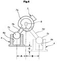
- FIG.5 shows this kind of the operation lever structure (for example, refer to Japanese Unexamined Utility Model Publication No. 5 - 18981).
- the operation lever structure is used in a combination switch device for an automobile 1 where a operation lever 7 is supported by a support shaft 8, the operation lever 7 being rotated relative to a casing 2 in the direction Y.
- the operation lever 7 equipped with a lever main body 7a which is rotated in the Y direction by the support shaft 8, and an arm section 7b formed integrally with the lever main body 7a.
- a spherical front end 7c of the arm section 7b is engaged in a concave section 4a of a movable member 4 (movable body) which slides on a base 3 located in a lower section of the casing 2.
- a plurality of stationary contact points (not shown) for a combination switch are disposed on the base member 3.
- a plurality of movable contact points 5 contacting the stationary points are mounted in a lower section of the movable member 4.
- a combination switch is mounted in a narrow, small steering column and therefore, a length from the front end 7c of the operation lever 7 to the arm section 7b close to the support shaft 8 is set to be short to reduce a size of the structure. Accordingly a stroke amount A of the movable member 4 has to be short.
- a stroke amount is increased to from a length A to a length B relative to the same rotation angle of the arm section 7b, but a large space to receive the movable member 4 or the like is required to correspond to an increased amount of the length in the arm section 7b', to increase a size of the entire structure.
- the present invention is made to solve the foregoing problems and has an object of providing an operation lever structure in which an entire length of an operation lever varies with a rotating operation angle of the operation lever, thereby to increase a stroke amount of a movable body regardless of a small space.
- One aspect of the invention is to provide an operation lever structure which comprises an operation lever supported by a support shaft to be rotated in a predetermined direction, an arm extending from the operation lever, and a movable body engaged with a front end of the arm to slidingly move the movable body in a predetermined direction by a rotating operation of the operation lever, wherein a length from the front end of the arm to the support shaft varies with a rotating operation angle of the operation lever.
- the operation lever includes a lever main body rotated in a predetermined direction by the support shaft, the arm supported movably to the lever main body a front end of which is engaged with the movable body, and an urging member to regularly urge the arm in the direction of the movable body.
- a hollow section is formed in the lever main body, as well as a hollow section is formed in at least a base side of the arm, wherein the base side of the arm is slidingly supported in the hollow section of the lever main body, and on the other hand, an urging member is interposed between the hollow section of the lever main body and the hollow section of the arm.
- the operation lever structure due to a simple structure where the arm is slidingly supported in the hollow section of the lever main body and the urging member interposed between the hollow section of the lever main body and the hollow section of the arm regularly urges the arm, an entire length of the arm of the operation lever securely varies with a rotating operation angle of the lever main body of the operation lever, and a stroke amount of the movable body is certainly increased within a small space.
- the stroke amount of the movable body can be increased within the small space.
- the operation lever includes a lever main body rotated in a predetermined direction by the support shaft, an arm supported movably to the lever main body a front end of which is engaged with the movable body, and an urging member to regularly urge the arm in the direction of the movable body, an entire length of the arm of the operation lever varies with a rotating operation angle of the lever main body of the operation lever, a stroke amount of the movable body is increased within a small space.
- FIG. 1 is a schematic construction view showing an operation lever structure of an embodiment 1 according to the present invention
- FIG.2 is an explanation view showing a sliding state of a movable member of the operation lever structure
- FIG.3 is an explanation view showing a comparison of varied states of an entire lever length of the operation lever structure
- FIG.4 is an explanation view showing a comparison in an operation angle and a sliding amount between the operation lever structure and the conventional structure. It is to be noted that a combination switch device for an automobile shown in FIG.5 is incorporated.
- FIG.1 - 3 An operation lever structure shown in FIG.1 - 3, is used for a combination switch device 1 for an automobile and an operation lever 10 is supported by a support shaft to a casing 2, the lever 10 being rotated in the direction Y (FIG.5).
- the operation lever 10 includes a lever main body 11 rotated in the direction Y by the support shaft 9, an arm 12 supported and slid in a hollow section 11b of the lever main body 11 a front end 12a of which is engaged in a concave section 15a of a movable member (movable body) 15 which slides along on a first base 13 located in a lower section in a casing 2, and a compression coil spring (an urging member) to regularly urge the front end 12a of the arm 12 in the direction of a concave section 15a of the movable member 15.
- a compression coil spring an urging member
- a cylindrical hollow section 11b is formed in the lever main body 11 from a front end 11a through the vicinity of a support shaft 9. And a cylindrical base end 12b of the arm 12 is slidingly supported in the hollow section 11b of the lever main body 11. And a columned hollow section 12c is formed in the arm 12 from the base end 12b of the arm 12 to the center of the spherical front end 12a.
- the compression coil spring 16 is interposed between in the hollow section 11b of the lever main body 11 and in the hollow section 12c of the arm 12.
- An extending length L of the arm 12 extended from the front end 11a of the lever main body 11 of the lever 10 varies corresponding to a rotating operation angle ⁇ of the operation lever 10 by the compression coil spring 16.
- a cylindrical concave section 15b is formed in a lower section of the movable member 15.
- a restrained pin 18 is urged and extended in the concave section 15b by a restrained spring 17.
- the restrained pin 18 is adapted to be engaged in a plurality of restrained grooves 14a formed on a top face of a second base 14 located in a lower section in the casing 2.
- the restrained pin 18 forms a restrained mechanism in cooperation with the restrained grooves 14a, which is adapted to temporarily engages the movable member 15 at each rotating position of the operation lever 10.
- a plurality of stationary contact points 14b for a combination switch are disposed on an upper face of the second base 14. And as shown in FIG.1, a movable contact point 19 contacting each of the above stationary contact points 14b is mounted in a lower section of the movable member 15.
- the operation lever 10 includes the lever main body 11 rotated in the directions Y and Z by the support shaft 9, the arm 12 supported and slid in the hollow section 11b of the lever main body 11 the front end 12a of which is engaged in the concave section 15a of the movable member 15, and the compression coil spring to regularly urge the arm 12 in the direction of the concave section 15a of the movable member 15.
- an extending length L of the arm 12 of the operation lever 10 can be varied and is lengthened corresponding to a rotating operation angle ⁇ of the lever main body 11 of the operation lever 10.
- a stroke amount D of the movable member 15 can be lengthened depending on a length of the spring 16.
- a stroke amount D of the movable member 15 can be lengthened within a small space in the casing 2 to improve a design flexibility of the base 14.
- the columned base 12b of the arm 12 is slidingly supported in the hollow section 11b of the lever main body 11, as well as the compression coil spring 16 is interposed between the hollow section 11b of the lever main body 11 and the hollow section 12c of the arm 12 whereby an extending length L of the arm 12 of the operation lever 10 can be varied with a rotating operation angle ⁇ of the lever main body 11 of the operation lever 10, to securely increase a stroke amount D of the movable member 15 even in a small space.
Landscapes
- Engineering & Computer Science (AREA)
- Mechanical Engineering (AREA)
- Switches With Compound Operations (AREA)
- Mechanical Control Devices (AREA)
- Rotary Switch, Piano Key Switch, And Lever Switch (AREA)
Applications Claiming Priority (2)
| Application Number | Priority Date | Filing Date | Title |
|---|---|---|---|
| JP2003334966A JP2005100227A (ja) | 2003-09-26 | 2003-09-26 | 操作レバー構造 |
| JP2003334966 | 2003-09-26 |
Publications (2)
| Publication Number | Publication Date |
|---|---|
| EP1518753A2 true EP1518753A2 (fr) | 2005-03-30 |
| EP1518753A3 EP1518753A3 (fr) | 2006-05-24 |
Family
ID=34191514
Family Applications (1)
| Application Number | Title | Priority Date | Filing Date |
|---|---|---|---|
| EP04022132A Withdrawn EP1518753A3 (fr) | 2003-09-26 | 2004-09-17 | Structure de levier d'actionnement |
Country Status (3)
| Country | Link |
|---|---|
| US (1) | US20050066765A1 (fr) |
| EP (1) | EP1518753A3 (fr) |
| JP (1) | JP2005100227A (fr) |
Cited By (1)
| Publication number | Priority date | Publication date | Assignee | Title |
|---|---|---|---|---|
| CN105022442A (zh) * | 2015-07-29 | 2015-11-04 | 重庆市秦潮机械配件加工厂 | 定位手柄 |
Families Citing this family (1)
| Publication number | Priority date | Publication date | Assignee | Title |
|---|---|---|---|---|
| US7608513B2 (en) * | 2007-01-25 | 2009-10-27 | Freescale Semiconductor, Inc. | Dual gate LDMOS device fabrication methods |
Family Cites Families (15)
| Publication number | Priority date | Publication date | Assignee | Title |
|---|---|---|---|---|
| US3818154A (en) * | 1973-04-09 | 1974-06-18 | S Presentey | Joystick type controller for switches |
| US3944847A (en) * | 1973-12-07 | 1976-03-16 | Kinnear Joseph D | Electrical disconnect switch |
| US4121065A (en) * | 1977-10-31 | 1978-10-17 | Cutler-Hammer, Inc. | Toggle switch lever lock |
| DE3734404A1 (de) * | 1987-10-12 | 1989-04-27 | Kostal Leopold Gmbh & Co Kg | Elektrischer schalter |
| US4947009A (en) * | 1987-10-28 | 1990-08-07 | Mcgill Manufacturing Company, Inc. | Conscious effort safety switch |
| US5041706A (en) * | 1990-04-26 | 1991-08-20 | Mcgill Manufacturing Company, Inc. | Safety switch with positive mounting retention and prolonged opening characteristics |
| JP2563129Y2 (ja) * | 1991-11-20 | 1998-02-18 | 株式会社東海理化電機製作所 | 自動車用スイッチのレバー操作装置 |
| US5744769A (en) * | 1993-09-13 | 1998-04-28 | United Technologies Automotive, Inc. | Electrical switch for use in an automotive vehicle |
| US5380964A (en) * | 1993-10-18 | 1995-01-10 | Deere & Company | Switch assembly |
| JP3565388B2 (ja) * | 1996-11-26 | 2004-09-15 | ナイルス株式会社 | 車両用レバースイッチの構造 |
| US6024643A (en) * | 1997-03-04 | 2000-02-15 | Intel Corporation | Player profile based proxy play |
| JP3890781B2 (ja) * | 1997-10-30 | 2007-03-07 | 株式会社セガ | コンピュータ読み取り可能な記憶媒体、ゲーム装置、及びゲームの画像表示方法 |
| JP3972230B2 (ja) * | 1999-02-15 | 2007-09-05 | 株式会社セガ | ゲーム装置、ゲーム装置の制御方法及び記録媒体 |
| JP4318354B2 (ja) * | 1999-10-04 | 2009-08-19 | ナイルス株式会社 | レバースイッチ |
| JP2003031082A (ja) * | 2001-07-12 | 2003-01-31 | Tokai Rika Co Ltd | スイッチ装置 |
-
2003
- 2003-09-26 JP JP2003334966A patent/JP2005100227A/ja active Pending
-
2004
- 2004-09-17 EP EP04022132A patent/EP1518753A3/fr not_active Withdrawn
- 2004-09-20 US US10/943,862 patent/US20050066765A1/en not_active Abandoned
Cited By (1)
| Publication number | Priority date | Publication date | Assignee | Title |
|---|---|---|---|---|
| CN105022442A (zh) * | 2015-07-29 | 2015-11-04 | 重庆市秦潮机械配件加工厂 | 定位手柄 |
Also Published As
| Publication number | Publication date |
|---|---|
| JP2005100227A (ja) | 2005-04-14 |
| EP1518753A3 (fr) | 2006-05-24 |
| US20050066765A1 (en) | 2005-03-31 |
Similar Documents
| Publication | Publication Date | Title |
|---|---|---|
| US20050199087A1 (en) | Single-motor power telescope and tilt steering column | |
| US20070278072A1 (en) | Turn signal switch for vehicle | |
| EP2492142B1 (fr) | Dispositif de commutation de signal de changement de direction | |
| US6796202B2 (en) | Switch operating mechanism | |
| EP1518753A2 (fr) | Structure de levier d'actionnement | |
| US20020075577A1 (en) | Manually foldable door mirror | |
| US9227560B2 (en) | Vehicle operating device | |
| US6660951B2 (en) | Canceling structure of combination switch | |
| US7422238B2 (en) | Rake design for steering column rake adjustment | |
| US5283403A (en) | Electric switch, in particular steering column switch for motor vehicles | |
| US6186022B1 (en) | Turn signal cancellation mechanism | |
| US6515243B2 (en) | Turn signal switch | |
| US5555973A (en) | Slide switch device | |
| CN212750697U (zh) | 一种汽车转向灯控制开关的手动复位结构 | |
| US5831231A (en) | Lever switch apparatus | |
| US4778955A (en) | Limit switch assembly | |
| US6437270B1 (en) | Pushbutton switch | |
| KR101141329B1 (ko) | 스위치 유니트 | |
| CN104114411A (zh) | 用于机动车辆的转向柱开关装置和具有转向柱开关装置的机动车辆 | |
| US20070039405A1 (en) | Reacting force controller for accelerator pedal | |
| JPH0436521Y2 (fr) | ||
| JP3686277B2 (ja) | 走行車両のステアリング装置 | |
| EP1528204B1 (fr) | Ensemble ressort à torsion | |
| KR20180046125A (ko) | 차량용 멀티 오퍼레이팅 스위치 유니트 | |
| JPH0687772U (ja) | 車両用変速装置 |
Legal Events
| Date | Code | Title | Description |
|---|---|---|---|
| PUAI | Public reference made under article 153(3) epc to a published international application that has entered the european phase |
Free format text: ORIGINAL CODE: 0009012 |
|
| AK | Designated contracting states |
Kind code of ref document: A2 Designated state(s): AT BE BG CH CY CZ DE DK EE ES FI FR GB GR HU IE IT LI LU MC NL PL PT RO SE SI SK TR |
|
| AX | Request for extension of the european patent |
Extension state: AL HR LT LV MK |
|
| PUAL | Search report despatched |
Free format text: ORIGINAL CODE: 0009013 |
|
| AK | Designated contracting states |
Kind code of ref document: A3 Designated state(s): AT BE BG CH CY CZ DE DK EE ES FI FR GB GR HU IE IT LI LU MC NL PL PT RO SE SI SK TR |
|
| AX | Request for extension of the european patent |
Extension state: AL HR LT LV MK |
|
| AKX | Designation fees paid | ||
| STAA | Information on the status of an ep patent application or granted ep patent |
Free format text: STATUS: THE APPLICATION IS DEEMED TO BE WITHDRAWN |
|
| 18D | Application deemed to be withdrawn |
Effective date: 20061125 |
|
| REG | Reference to a national code |
Ref country code: DE Ref legal event code: 8566 |