EP1518753A2 - Operation lever structure - Google Patents
Operation lever structure Download PDFInfo
- Publication number
- EP1518753A2 EP1518753A2 EP04022132A EP04022132A EP1518753A2 EP 1518753 A2 EP1518753 A2 EP 1518753A2 EP 04022132 A EP04022132 A EP 04022132A EP 04022132 A EP04022132 A EP 04022132A EP 1518753 A2 EP1518753 A2 EP 1518753A2
- Authority
- EP
- European Patent Office
- Prior art keywords
- operation lever
- arm
- lever
- main body
- hollow section
- Prior art date
- Legal status (The legal status is an assumption and is not a legal conclusion. Google has not performed a legal analysis and makes no representation as to the accuracy of the status listed.)
- Withdrawn
Links
Images


Classifications
-
- B—PERFORMING OPERATIONS; TRANSPORTING
- B60—VEHICLES IN GENERAL
- B60Q—ARRANGEMENT OF SIGNALLING OR LIGHTING DEVICES, THE MOUNTING OR SUPPORTING THEREOF OR CIRCUITS THEREFOR, FOR VEHICLES IN GENERAL
- B60Q1/00—Arrangement of optical signalling or lighting devices, the mounting or supporting thereof or circuits therefor
- B60Q1/02—Arrangement of optical signalling or lighting devices, the mounting or supporting thereof or circuits therefor the devices being primarily intended to illuminate the way ahead or to illuminate other areas of way or environments
- B60Q1/04—Arrangement of optical signalling or lighting devices, the mounting or supporting thereof or circuits therefor the devices being primarily intended to illuminate the way ahead or to illuminate other areas of way or environments the devices being headlights
- B60Q1/14—Arrangement of optical signalling or lighting devices, the mounting or supporting thereof or circuits therefor the devices being primarily intended to illuminate the way ahead or to illuminate other areas of way or environments the devices being headlights having dimming means
- B60Q1/1446—Arrangement of optical signalling or lighting devices, the mounting or supporting thereof or circuits therefor the devices being primarily intended to illuminate the way ahead or to illuminate other areas of way or environments the devices being headlights having dimming means controlled by mechanically actuated switches
- B60Q1/1453—Hand actuated switches
- B60Q1/1461—Multifunction switches for dimming headlights and controlling additional devices, e.g. for controlling direction indicating lights
- B60Q1/1469—Multifunction switches for dimming headlights and controlling additional devices, e.g. for controlling direction indicating lights controlled by or attached to a single lever, e.g. steering column stalk switches
-
- Y—GENERAL TAGGING OF NEW TECHNOLOGICAL DEVELOPMENTS; GENERAL TAGGING OF CROSS-SECTIONAL TECHNOLOGIES SPANNING OVER SEVERAL SECTIONS OF THE IPC; TECHNICAL SUBJECTS COVERED BY FORMER USPC CROSS-REFERENCE ART COLLECTIONS [XRACs] AND DIGESTS
- Y10—TECHNICAL SUBJECTS COVERED BY FORMER USPC
- Y10T—TECHNICAL SUBJECTS COVERED BY FORMER US CLASSIFICATION
- Y10T74/00—Machine element or mechanism
- Y10T74/20—Control lever and linkage systems
- Y10T74/20576—Elements
- Y10T74/20582—Levers
- Y10T74/20612—Hand
- Y10T74/20624—Adjustable
Definitions
- the present invention relates to an operation lever structure and in particular, to an operation lever structure suitable for a combination switch device for an automobile or the like.
- FIG.5 shows this kind of the operation lever structure (for example, refer to Japanese Unexamined Utility Model Publication No. 5 - 18981).
- the operation lever structure is used in a combination switch device for an automobile 1 where a operation lever 7 is supported by a support shaft 8, the operation lever 7 being rotated relative to a casing 2 in the direction Y.
- the operation lever 7 equipped with a lever main body 7a which is rotated in the Y direction by the support shaft 8, and an arm section 7b formed integrally with the lever main body 7a.
- a spherical front end 7c of the arm section 7b is engaged in a concave section 4a of a movable member 4 (movable body) which slides on a base 3 located in a lower section of the casing 2.
- a plurality of stationary contact points (not shown) for a combination switch are disposed on the base member 3.
- a plurality of movable contact points 5 contacting the stationary points are mounted in a lower section of the movable member 4.
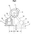
- a combination switch is mounted in a narrow, small steering column and therefore, a length from the front end 7c of the operation lever 7 to the arm section 7b close to the support shaft 8 is set to be short to reduce a size of the structure. Accordingly a stroke amount A of the movable member 4 has to be short.
- a stroke amount is increased to from a length A to a length B relative to the same rotation angle of the arm section 7b, but a large space to receive the movable member 4 or the like is required to correspond to an increased amount of the length in the arm section 7b', to increase a size of the entire structure.
- the present invention is made to solve the foregoing problems and has an object of providing an operation lever structure in which an entire length of an operation lever varies with a rotating operation angle of the operation lever, thereby to increase a stroke amount of a movable body regardless of a small space.
- One aspect of the invention is to provide an operation lever structure which comprises an operation lever supported by a support shaft to be rotated in a predetermined direction, an arm extending from the operation lever, and a movable body engaged with a front end of the arm to slidingly move the movable body in a predetermined direction by a rotating operation of the operation lever, wherein a length from the front end of the arm to the support shaft varies with a rotating operation angle of the operation lever.
- the operation lever includes a lever main body rotated in a predetermined direction by the support shaft, the arm supported movably to the lever main body a front end of which is engaged with the movable body, and an urging member to regularly urge the arm in the direction of the movable body.
- a hollow section is formed in the lever main body, as well as a hollow section is formed in at least a base side of the arm, wherein the base side of the arm is slidingly supported in the hollow section of the lever main body, and on the other hand, an urging member is interposed between the hollow section of the lever main body and the hollow section of the arm.
- the operation lever structure due to a simple structure where the arm is slidingly supported in the hollow section of the lever main body and the urging member interposed between the hollow section of the lever main body and the hollow section of the arm regularly urges the arm, an entire length of the arm of the operation lever securely varies with a rotating operation angle of the lever main body of the operation lever, and a stroke amount of the movable body is certainly increased within a small space.
- the stroke amount of the movable body can be increased within the small space.
- the operation lever includes a lever main body rotated in a predetermined direction by the support shaft, an arm supported movably to the lever main body a front end of which is engaged with the movable body, and an urging member to regularly urge the arm in the direction of the movable body, an entire length of the arm of the operation lever varies with a rotating operation angle of the lever main body of the operation lever, a stroke amount of the movable body is increased within a small space.
- FIG. 1 is a schematic construction view showing an operation lever structure of an embodiment 1 according to the present invention
- FIG.2 is an explanation view showing a sliding state of a movable member of the operation lever structure
- FIG.3 is an explanation view showing a comparison of varied states of an entire lever length of the operation lever structure
- FIG.4 is an explanation view showing a comparison in an operation angle and a sliding amount between the operation lever structure and the conventional structure. It is to be noted that a combination switch device for an automobile shown in FIG.5 is incorporated.
- FIG.1 - 3 An operation lever structure shown in FIG.1 - 3, is used for a combination switch device 1 for an automobile and an operation lever 10 is supported by a support shaft to a casing 2, the lever 10 being rotated in the direction Y (FIG.5).
- the operation lever 10 includes a lever main body 11 rotated in the direction Y by the support shaft 9, an arm 12 supported and slid in a hollow section 11b of the lever main body 11 a front end 12a of which is engaged in a concave section 15a of a movable member (movable body) 15 which slides along on a first base 13 located in a lower section in a casing 2, and a compression coil spring (an urging member) to regularly urge the front end 12a of the arm 12 in the direction of a concave section 15a of the movable member 15.
- a compression coil spring an urging member
- a cylindrical hollow section 11b is formed in the lever main body 11 from a front end 11a through the vicinity of a support shaft 9. And a cylindrical base end 12b of the arm 12 is slidingly supported in the hollow section 11b of the lever main body 11. And a columned hollow section 12c is formed in the arm 12 from the base end 12b of the arm 12 to the center of the spherical front end 12a.
- the compression coil spring 16 is interposed between in the hollow section 11b of the lever main body 11 and in the hollow section 12c of the arm 12.
- An extending length L of the arm 12 extended from the front end 11a of the lever main body 11 of the lever 10 varies corresponding to a rotating operation angle ⁇ of the operation lever 10 by the compression coil spring 16.
- a cylindrical concave section 15b is formed in a lower section of the movable member 15.
- a restrained pin 18 is urged and extended in the concave section 15b by a restrained spring 17.
- the restrained pin 18 is adapted to be engaged in a plurality of restrained grooves 14a formed on a top face of a second base 14 located in a lower section in the casing 2.
- the restrained pin 18 forms a restrained mechanism in cooperation with the restrained grooves 14a, which is adapted to temporarily engages the movable member 15 at each rotating position of the operation lever 10.
- a plurality of stationary contact points 14b for a combination switch are disposed on an upper face of the second base 14. And as shown in FIG.1, a movable contact point 19 contacting each of the above stationary contact points 14b is mounted in a lower section of the movable member 15.
- the operation lever 10 includes the lever main body 11 rotated in the directions Y and Z by the support shaft 9, the arm 12 supported and slid in the hollow section 11b of the lever main body 11 the front end 12a of which is engaged in the concave section 15a of the movable member 15, and the compression coil spring to regularly urge the arm 12 in the direction of the concave section 15a of the movable member 15.
- an extending length L of the arm 12 of the operation lever 10 can be varied and is lengthened corresponding to a rotating operation angle ⁇ of the lever main body 11 of the operation lever 10.
- a stroke amount D of the movable member 15 can be lengthened depending on a length of the spring 16.
- a stroke amount D of the movable member 15 can be lengthened within a small space in the casing 2 to improve a design flexibility of the base 14.
- the columned base 12b of the arm 12 is slidingly supported in the hollow section 11b of the lever main body 11, as well as the compression coil spring 16 is interposed between the hollow section 11b of the lever main body 11 and the hollow section 12c of the arm 12 whereby an extending length L of the arm 12 of the operation lever 10 can be varied with a rotating operation angle ⁇ of the lever main body 11 of the operation lever 10, to securely increase a stroke amount D of the movable member 15 even in a small space.
Abstract
Description
- The present invention relates to an operation lever structure and in particular, to an operation lever structure suitable for a combination switch device for an automobile or the like.
- FIG.5 shows this kind of the operation lever structure (for example, refer to Japanese Unexamined Utility Model Publication No. 5 - 18981).
- The operation lever structure is used in a combination switch device for an automobile 1 where a
operation lever 7 is supported by asupport shaft 8, theoperation lever 7 being rotated relative to acasing 2 in the direction Y. - As shown in FIG. 5 and 6, the
operation lever 7 equipped with a levermain body 7a which is rotated in the Y direction by thesupport shaft 8, and anarm section 7b formed integrally with the levermain body 7a. - A
spherical front end 7c of thearm section 7b is engaged in aconcave section 4a of a movable member 4 (movable body) which slides on abase 3 located in a lower section of thecasing 2. - And when the
operation lever 7 is rotated in the backward direction Y, themovable member 4 slides in the direction X by a predetermined amount A through thespherical front end 7c of thearm section 7b. - In addition, a plurality of stationary contact points (not shown) for a combination switch are disposed on the
base member 3. And a plurality of movable contact points 5 contacting the stationary points are mounted in a lower section of themovable member 4. - However, in the conventional operation lever structure, a combination switch is mounted in a narrow, small steering column and therefore, a length from the
front end 7c of theoperation lever 7 to thearm section 7b close to thesupport shaft 8 is set to be short to reduce a size of the structure. Accordingly a stroke amount A of themovable member 4 has to be short. For coping with this problem, as shown by a dotted line in FIG.6, if along arm section 7b' is used, a stroke amount is increased to from a length A to a length B relative to the same rotation angle of thearm section 7b, but a large space to receive themovable member 4 or the like is required to correspond to an increased amount of the length in thearm section 7b', to increase a size of the entire structure. - And if the stroke amount of the
movable member 4 is short, the number and the shape of the stationary contact points on themovable member 4 are limited and flexibility of a base design is limited for a secure on/off operations. - Accordingly the present invention is made to solve the foregoing problems and has an object of providing an operation lever structure in which an entire length of an operation lever varies with a rotating operation angle of the operation lever, thereby to increase a stroke amount of a movable body regardless of a small space.
- One aspect of the invention is to provide an operation lever structure which comprises an operation lever supported by a support shaft to be rotated in a predetermined direction, an arm extending from the operation lever, and a movable body engaged with a front end of the arm to slidingly move the movable body in a predetermined direction by a rotating operation of the operation lever, wherein a length from the front end of the arm to the support shaft varies with a rotating operation angle of the operation lever.
- Since in this operation lever structure an entire length of the operation lever varies with the rotating operation angle thereof, a stroke amount of the movable body is increased within a small space.
- In the operation lever structure, the operation lever includes a lever main body rotated in a predetermined direction by the support shaft, the arm supported movably to the lever main body a front end of which is engaged with the movable body, and an urging member to regularly urge the arm in the direction of the movable body.
- Since in this operation lever structure an entire length of the arm of the operation lever varies with a rotating operation angle of the lever main body of the operation lever, a stroke amount of the movable body is increased within a small space and with a simple structure.
- In the operation lever structure, a hollow section is formed in the lever main body, as well as a hollow section is formed in at least a base side of the arm, wherein the base side of the arm is slidingly supported in the hollow section of the lever main body, and on the other hand, an urging member is interposed between the hollow section of the lever main body and the hollow section of the arm.
- In the operation lever structure, due to a simple structure where the arm is slidingly supported in the hollow section of the lever main body and the urging member interposed between the hollow section of the lever main body and the hollow section of the arm regularly urges the arm, an entire length of the arm of the operation lever securely varies with a rotating operation angle of the lever main body of the operation lever, and a stroke amount of the movable body is certainly increased within a small space.
- As explained above, according to one aspect of the invention, since the entire length of the operation lever varies with the rotating operation angle thereof, the stroke amount of the movable body can be increased within the small space.
- Further, since the operation lever includes a lever main body rotated in a predetermined direction by the support shaft, an arm supported movably to the lever main body a front end of which is engaged with the movable body, and an urging member to regularly urge the arm in the direction of the movable body, an entire length of the arm of the operation lever varies with a rotating operation angle of the lever main body of the operation lever, a stroke amount of the movable body is increased within a small space.
- Furthermore, since the base side of the arm is slidingly supported in the hollow section in the front side of the lever main body, as well as the urging member is interposed between the hollow section of the lever main body and the hollow section of the base side of the arm, an entire length of the arm of the operation lever securely varies with a rotating operation angle of the lever main body of the operation lever, and a stroke amount of the movable body is certainly increased within a small space.
- These and other objects, features, aspects and advantages of the present invention will be become apparent to those skilled in the art from the following detailed description, which, taken in conjunction with the annexed drawings, discloses preferred embodiments of the present invention.
-
- FIG. 1 is a schematic construction view showing an operation lever structure of an embodiment 1.
- FIG.2 is an explanation view showing a sliding state of a movable member of the operation lever structure.
- FIG.3 is an explanation view showing a comparison of varied states of an entire lever length of the operation lever structure.
- FIG.4 is an explanation view showing a comparison in an operation angle and a sliding amount between the operation lever structure and the conventional structure.
- FIG.5 is a cross sectional view of a combination switch device using a conventional operation lever structure.
- FIG.6 is a view explaining a slide amount of a movable member of a conventional operation lever structure.
-
- The present invention will be explained in detail based upon an embodiment of the present invention shown in accompanying drawings as follows.
- FIG. 1 is a schematic construction view showing an operation lever structure of an embodiment 1 according to the present invention, FIG.2 is an explanation view showing a sliding state of a movable member of the operation lever structure, FIG.3 is an explanation view showing a comparison of varied states of an entire lever length of the operation lever structure, FIG.4 is an explanation view showing a comparison in an operation angle and a sliding amount between the operation lever structure and the conventional structure. It is to be noted that a combination switch device for an automobile shown in FIG.5 is incorporated.
- An operation lever structure shown in FIG.1 - 3, is used for a combination switch device 1 for an automobile and an
operation lever 10 is supported by a support shaft to acasing 2, thelever 10 being rotated in the direction Y (FIG.5). - The
operation lever 10 includes a levermain body 11 rotated in the direction Y by thesupport shaft 9, anarm 12 supported and slid in ahollow section 11b of the levermain body 11 afront end 12a of which is engaged in aconcave section 15a of a movable member (movable body) 15 which slides along on afirst base 13 located in a lower section in acasing 2, and a compression coil spring (an urging member) to regularly urge thefront end 12a of thearm 12 in the direction of aconcave section 15a of themovable member 15. - As shown in FIG.1 - 3, a cylindrical
hollow section 11b is formed in the levermain body 11 from afront end 11a through the vicinity of asupport shaft 9. And acylindrical base end 12b of thearm 12 is slidingly supported in thehollow section 11b of the levermain body 11. And a columnedhollow section 12c is formed in thearm 12 from thebase end 12b of thearm 12 to the center of thespherical front end 12a. Thecompression coil spring 16 is interposed between in thehollow section 11b of the levermain body 11 and in thehollow section 12c of thearm 12. An extending length L of thearm 12 extended from thefront end 11a of the levermain body 11 of thelever 10 varies corresponding to a rotating operation angle □ of the operation lever 10 by thecompression coil spring 16. - Further, as shown in FIG.1, a cylindrical
concave section 15b is formed in a lower section of themovable member 15. A restrainedpin 18 is urged and extended in theconcave section 15b by a restrainedspring 17. The restrainedpin 18 is adapted to be engaged in a plurality ofrestrained grooves 14a formed on a top face of asecond base 14 located in a lower section in thecasing 2. The restrainedpin 18 forms a restrained mechanism in cooperation with therestrained grooves 14a, which is adapted to temporarily engages themovable member 15 at each rotating position of theoperation lever 10. - Further , as shown in FIG. 1 and 2, a plurality of
stationary contact points 14b for a combination switch are disposed on an upper face of thesecond base 14. And as shown in FIG.1,amovable contact point 19 contacting each of the abovestationary contact points 14b is mounted in a lower section of themovable member 15. - According to the operation lever structure of the embodiment 1, as shown in FIG.3, when the
operation lever 10 is operated to be rotated in the direction Z, thecompression coil spring 16 is compressed, and themovable member 15 is traveled from α position to β position (stroke amount D) by thespherical front end 12a of thearm 12 traveled in theconcave section 15a of themovable member 15. On this occasion, an extending length L of thearm 12 of theoperation lever 10 varies with a rotating operation angle of theoperation lever 10. Even if theoperation lever 10 is operated to be rotated in the direction Y, themovable member 15 can be traveled by a stroke amount D the same as in the direction Z. A relation of the rotating operation angle of theoperation lever 10 and the stroke amount D of themovable member 15 is shown in a solid line of FIG.4. - Thus the
operation lever 10 includes the levermain body 11 rotated in the directions Y and Z by thesupport shaft 9, thearm 12 supported and slid in thehollow section 11b of the levermain body 11 thefront end 12a of which is engaged in theconcave section 15a of themovable member 15, and the compression coil spring to regularly urge thearm 12 in the direction of theconcave section 15a of themovable member 15. Accordingly as shown in FIG.4, as compared to the conventional structure, an extending length L of thearm 12 of theoperation lever 10 can be varied and is lengthened corresponding to a rotating operation angle of the levermain body 11 of theoperation lever 10. Namely a stroke amount D of themovable member 15 can be lengthened depending on a length of thespring 16. As a result, a stroke amount D of themovable member 15 can be lengthened within a small space in thecasing 2 to improve a design flexibility of thebase 14. - In particular, the columned
base 12b of thearm 12 is slidingly supported in thehollow section 11b of the levermain body 11, as well as thecompression coil spring 16 is interposed between thehollow section 11b of the levermain body 11 and thehollow section 12c of thearm 12 whereby an extending length L of thearm 12 of theoperation lever 10 can be varied with a rotating operation angle of the levermain body 11 of theoperation lever 10, to securely increase a stroke amount D of themovable member 15 even in a small space. - In addition, according to the embodiment 1, a case where the operation lever is operated to be rotated around the
support shaft 9 is explained, but the present invention may be applied to a case where the operation lever is operated to be rotated in the direction perpendicular to thesupport shaft 9, and is not limited to a case where the combination switch is used. - While only selected embodiment has been chosen to illustrate the present invention, it will be apparent to those skilled in the art from this disclosure that various changes and modifications can be made herein without departing from the scope of the invention as defined in the appended claims. Furthermore, the foregoing description of the embodiment according to the present invention is provided for illustration only, and not for the purpose of limiting the invention as defined by the appended claims and their equivalents.
Claims (3)
- An operation lever structure comprising:an operation lever supported by a support shaft to be rotated in a predetermined direction;an arm extending from the operation lever; anda movable body engaged with a front end of the arm to slidingly move the movable body in a predetermined direction by a rotating operation of the operation lever, whereina length from the front end of the arm to the support shaft varies with a rotating operation angle of the operation lever.
- The operation lever structure as defined in claim 1, wherein
the operation lever includes:a lever main body rotated in a predetermined direction by the support shaft;the arm supported movably to the lever main body, a front end of the arm being engaged with the movable body; andan urging member to regularly urge the arm in the direction of the movable body. - The operation lever structure as defined in claim 2, wherein
a first hollow section is formed in the lever main body, as well as a second hollow section is formed in at least a base side of the arm, the base side of the arm is supported in the first hollow section to be slid therein, and an urging member is interposed between the first hollow section and the second hollow section.
Applications Claiming Priority (2)
| Application Number | Priority Date | Filing Date | Title |
|---|---|---|---|
| JP2003334966 | 2003-09-26 | ||
| JP2003334966A JP2005100227A (en) | 2003-09-26 | 2003-09-26 | Operation lever structure |
Publications (2)
| Publication Number | Publication Date |
|---|---|
| EP1518753A2 true EP1518753A2 (en) | 2005-03-30 |
| EP1518753A3 EP1518753A3 (en) | 2006-05-24 |
Family
ID=34191514
Family Applications (1)
| Application Number | Title | Priority Date | Filing Date |
|---|---|---|---|
| EP04022132A Withdrawn EP1518753A3 (en) | 2003-09-26 | 2004-09-17 | Operation lever structure |
Country Status (3)
| Country | Link |
|---|---|
| US (1) | US20050066765A1 (en) |
| EP (1) | EP1518753A3 (en) |
| JP (1) | JP2005100227A (en) |
Cited By (1)
| Publication number | Priority date | Publication date | Assignee | Title |
|---|---|---|---|---|
| CN105022442A (en) * | 2015-07-29 | 2015-11-04 | 重庆市秦潮机械配件加工厂 | Positioning handle |
Families Citing this family (1)
| Publication number | Priority date | Publication date | Assignee | Title |
|---|---|---|---|---|
| US7608513B2 (en) * | 2007-01-25 | 2009-10-27 | Freescale Semiconductor, Inc. | Dual gate LDMOS device fabrication methods |
Citations (3)
| Publication number | Priority date | Publication date | Assignee | Title |
|---|---|---|---|---|
| DE3734404A1 (en) * | 1987-10-12 | 1989-04-27 | Kostal Leopold Gmbh & Co Kg | Electrical switch |
| DE4238070A1 (en) * | 1991-11-20 | 1993-05-27 | Tokai Rika Co Ltd | Switch actuator lever mechanism for vehicle steering column - has coupling element mounted on main lever that pivots to displace sliding element coupled to contacts |
| US20030010616A1 (en) * | 2001-07-12 | 2003-01-16 | Kabushiki Kaisha Tokai Rika Denki Seisakusho | Switch apparatus |
Family Cites Families (12)
| Publication number | Priority date | Publication date | Assignee | Title |
|---|---|---|---|---|
| US3818154A (en) * | 1973-04-09 | 1974-06-18 | S Presentey | Joystick type controller for switches |
| US3944847A (en) * | 1973-12-07 | 1976-03-16 | Kinnear Joseph D | Electrical disconnect switch |
| US4121065A (en) * | 1977-10-31 | 1978-10-17 | Cutler-Hammer, Inc. | Toggle switch lever lock |
| US4947009A (en) * | 1987-10-28 | 1990-08-07 | Mcgill Manufacturing Company, Inc. | Conscious effort safety switch |
| US5041706A (en) * | 1990-04-26 | 1991-08-20 | Mcgill Manufacturing Company, Inc. | Safety switch with positive mounting retention and prolonged opening characteristics |
| US5744769A (en) * | 1993-09-13 | 1998-04-28 | United Technologies Automotive, Inc. | Electrical switch for use in an automotive vehicle |
| US5380964A (en) * | 1993-10-18 | 1995-01-10 | Deere & Company | Switch assembly |
| JP3565388B2 (en) * | 1996-11-26 | 2004-09-15 | ナイルス株式会社 | Structure of vehicle lever switch |
| US6024643A (en) * | 1997-03-04 | 2000-02-15 | Intel Corporation | Player profile based proxy play |
| JP3890781B2 (en) * | 1997-10-30 | 2007-03-07 | 株式会社セガ | Computer-readable storage medium, game device, and game image display method |
| JP3972230B2 (en) * | 1999-02-15 | 2007-09-05 | 株式会社セガ | GAME DEVICE, GAME DEVICE CONTROL METHOD, AND RECORDING MEDIUM |
| JP4318354B2 (en) * | 1999-10-04 | 2009-08-19 | ナイルス株式会社 | Lever switch |
-
2003
- 2003-09-26 JP JP2003334966A patent/JP2005100227A/en active Pending
-
2004
- 2004-09-17 EP EP04022132A patent/EP1518753A3/en not_active Withdrawn
- 2004-09-20 US US10/943,862 patent/US20050066765A1/en not_active Abandoned
Patent Citations (3)
| Publication number | Priority date | Publication date | Assignee | Title |
|---|---|---|---|---|
| DE3734404A1 (en) * | 1987-10-12 | 1989-04-27 | Kostal Leopold Gmbh & Co Kg | Electrical switch |
| DE4238070A1 (en) * | 1991-11-20 | 1993-05-27 | Tokai Rika Co Ltd | Switch actuator lever mechanism for vehicle steering column - has coupling element mounted on main lever that pivots to displace sliding element coupled to contacts |
| US20030010616A1 (en) * | 2001-07-12 | 2003-01-16 | Kabushiki Kaisha Tokai Rika Denki Seisakusho | Switch apparatus |
Cited By (1)
| Publication number | Priority date | Publication date | Assignee | Title |
|---|---|---|---|---|
| CN105022442A (en) * | 2015-07-29 | 2015-11-04 | 重庆市秦潮机械配件加工厂 | Positioning handle |
Also Published As
| Publication number | Publication date |
|---|---|
| US20050066765A1 (en) | 2005-03-31 |
| JP2005100227A (en) | 2005-04-14 |
| EP1518753A3 (en) | 2006-05-24 |
Similar Documents
| Publication | Publication Date | Title |
|---|---|---|
| US7293481B2 (en) | Single-motor power telescope and tilt steering column | |
| US5672855A (en) | Canceling mechanism for a vehicular turn signal switch | |
| CN100533626C (en) | Deflector rod switch | |
| EP2492142B1 (en) | Turn signal switch device | |
| US20060151985A1 (en) | Rake design for steering column rake adjustment | |
| EP1300859B1 (en) | Switch operating mechanism | |
| EP1518753A2 (en) | Operation lever structure | |
| US20020075577A1 (en) | Manually foldable door mirror | |
| US6660951B2 (en) | Canceling structure of combination switch | |
| US6515243B2 (en) | Turn signal switch | |
| US5555973A (en) | Slide switch device | |
| US20070039405A1 (en) | Reacting force controller for accelerator pedal | |
| US5831231A (en) | Lever switch apparatus | |
| US4778955A (en) | Limit switch assembly | |
| US9227560B2 (en) | Vehicle operating device | |
| KR101141329B1 (en) | Tiltable switching unit | |
| CN212750697U (en) | Manual reset structure of automobile steering lamp control switch | |
| CN220064785U (en) | Force feedback mechanism and interaction equipment | |
| KR20180046125A (en) | Vehicular multi-operating switching unit | |
| JP3686277B2 (en) | Steering device for traveling vehicle | |
| EP1528204B1 (en) | Torsion spring assembly | |
| JPH0687772U (en) | Transmission for vehicle | |
| JP2924656B2 (en) | Rotary switch with push button switch | |
| JPH0436521Y2 (en) | ||
| KR20180046126A (en) | Vehicular multi-operating switching unit |
Legal Events
| Date | Code | Title | Description |
|---|---|---|---|
| PUAI | Public reference made under article 153(3) epc to a published international application that has entered the european phase |
Free format text: ORIGINAL CODE: 0009012 |
|
| AK | Designated contracting states |
Kind code of ref document: A2 Designated state(s): AT BE BG CH CY CZ DE DK EE ES FI FR GB GR HU IE IT LI LU MC NL PL PT RO SE SI SK TR |
|
| AX | Request for extension of the european patent |
Extension state: AL HR LT LV MK |
|
| PUAL | Search report despatched |
Free format text: ORIGINAL CODE: 0009013 |
|
| AK | Designated contracting states |
Kind code of ref document: A3 Designated state(s): AT BE BG CH CY CZ DE DK EE ES FI FR GB GR HU IE IT LI LU MC NL PL PT RO SE SI SK TR |
|
| AX | Request for extension of the european patent |
Extension state: AL HR LT LV MK |
|
| AKX | Designation fees paid | ||
| STAA | Information on the status of an ep patent application or granted ep patent |
Free format text: STATUS: THE APPLICATION IS DEEMED TO BE WITHDRAWN |
|
| 18D | Application deemed to be withdrawn |
Effective date: 20061125 |
|
| REG | Reference to a national code |
Ref country code: DE Ref legal event code: 8566 |