EP1518679A2 - Méthode et appareil d'éjection de goutellettes - Google Patents
Méthode et appareil d'éjection de goutellettes Download PDFInfo
- Publication number
- EP1518679A2 EP1518679A2 EP04022812A EP04022812A EP1518679A2 EP 1518679 A2 EP1518679 A2 EP 1518679A2 EP 04022812 A EP04022812 A EP 04022812A EP 04022812 A EP04022812 A EP 04022812A EP 1518679 A2 EP1518679 A2 EP 1518679A2
- Authority
- EP
- European Patent Office
- Prior art keywords
- liquid
- drive waveform
- taking
- nozzle
- droplet
- Prior art date
- Legal status (The legal status is an assumption and is not a legal conclusion. Google has not performed a legal analysis and makes no representation as to the accuracy of the status listed.)
- Granted
Links
- 238000007599 discharging Methods 0.000 title claims abstract description 51
- 238000000034 method Methods 0.000 title claims abstract description 23
- 239000007788 liquid Substances 0.000 claims abstract description 174
- 230000005540 biological transmission Effects 0.000 claims abstract description 6
- 230000005499 meniscus Effects 0.000 claims description 73
- 238000006073 displacement reaction Methods 0.000 claims description 52
- 230000001133 acceleration Effects 0.000 description 14
- 238000010586 diagram Methods 0.000 description 10
- 230000007423 decrease Effects 0.000 description 4
- 238000012986 modification Methods 0.000 description 2
- 230000004048 modification Effects 0.000 description 2
- 238000003825 pressing Methods 0.000 description 2
- 230000000087 stabilizing effect Effects 0.000 description 2
- 239000000919 ceramic Substances 0.000 description 1
- 238000010276 construction Methods 0.000 description 1
- 230000000694 effects Effects 0.000 description 1
- 238000010008 shearing Methods 0.000 description 1
- 230000006641 stabilisation Effects 0.000 description 1
- 238000011105 stabilization Methods 0.000 description 1
- 230000002123 temporal effect Effects 0.000 description 1
Images


Classifications
-
- B—PERFORMING OPERATIONS; TRANSPORTING
- B41—PRINTING; LINING MACHINES; TYPEWRITERS; STAMPS
- B41J—TYPEWRITERS; SELECTIVE PRINTING MECHANISMS, i.e. MECHANISMS PRINTING OTHERWISE THAN FROM A FORME; CORRECTION OF TYPOGRAPHICAL ERRORS
- B41J2/00—Typewriters or selective printing mechanisms characterised by the printing or marking process for which they are designed
- B41J2/005—Typewriters or selective printing mechanisms characterised by the printing or marking process for which they are designed characterised by bringing liquid or particles selectively into contact with a printing material
- B41J2/01—Ink jet
- B41J2/135—Nozzles
- B41J2/14—Structure thereof only for on-demand ink jet heads
- B41J2/14201—Structure of print heads with piezoelectric elements
- B41J2/14209—Structure of print heads with piezoelectric elements of finger type, chamber walls consisting integrally of piezoelectric material
-
- B—PERFORMING OPERATIONS; TRANSPORTING
- B41—PRINTING; LINING MACHINES; TYPEWRITERS; STAMPS
- B41J—TYPEWRITERS; SELECTIVE PRINTING MECHANISMS, i.e. MECHANISMS PRINTING OTHERWISE THAN FROM A FORME; CORRECTION OF TYPOGRAPHICAL ERRORS
- B41J2/00—Typewriters or selective printing mechanisms characterised by the printing or marking process for which they are designed
- B41J2/005—Typewriters or selective printing mechanisms characterised by the printing or marking process for which they are designed characterised by bringing liquid or particles selectively into contact with a printing material
- B41J2/01—Ink jet
- B41J2/015—Ink jet characterised by the jet generation process
- B41J2/04—Ink jet characterised by the jet generation process generating single droplets or particles on demand
- B41J2/045—Ink jet characterised by the jet generation process generating single droplets or particles on demand by pressure, e.g. electromechanical transducers
- B41J2/04501—Control methods or devices therefor, e.g. driver circuits, control circuits
- B41J2/04571—Control methods or devices therefor, e.g. driver circuits, control circuits detecting viscosity
-
- B—PERFORMING OPERATIONS; TRANSPORTING
- B41—PRINTING; LINING MACHINES; TYPEWRITERS; STAMPS
- B41J—TYPEWRITERS; SELECTIVE PRINTING MECHANISMS, i.e. MECHANISMS PRINTING OTHERWISE THAN FROM A FORME; CORRECTION OF TYPOGRAPHICAL ERRORS
- B41J2/00—Typewriters or selective printing mechanisms characterised by the printing or marking process for which they are designed
- B41J2/005—Typewriters or selective printing mechanisms characterised by the printing or marking process for which they are designed characterised by bringing liquid or particles selectively into contact with a printing material
- B41J2/01—Ink jet
- B41J2/015—Ink jet characterised by the jet generation process
- B41J2/04—Ink jet characterised by the jet generation process generating single droplets or particles on demand
- B41J2/045—Ink jet characterised by the jet generation process generating single droplets or particles on demand by pressure, e.g. electromechanical transducers
- B41J2/04501—Control methods or devices therefor, e.g. driver circuits, control circuits
- B41J2/04581—Control methods or devices therefor, e.g. driver circuits, control circuits controlling heads based on piezoelectric elements
-
- B—PERFORMING OPERATIONS; TRANSPORTING
- B41—PRINTING; LINING MACHINES; TYPEWRITERS; STAMPS
- B41J—TYPEWRITERS; SELECTIVE PRINTING MECHANISMS, i.e. MECHANISMS PRINTING OTHERWISE THAN FROM A FORME; CORRECTION OF TYPOGRAPHICAL ERRORS
- B41J2/00—Typewriters or selective printing mechanisms characterised by the printing or marking process for which they are designed
- B41J2/005—Typewriters or selective printing mechanisms characterised by the printing or marking process for which they are designed characterised by bringing liquid or particles selectively into contact with a printing material
- B41J2/01—Ink jet
- B41J2/015—Ink jet characterised by the jet generation process
- B41J2/04—Ink jet characterised by the jet generation process generating single droplets or particles on demand
- B41J2/045—Ink jet characterised by the jet generation process generating single droplets or particles on demand by pressure, e.g. electromechanical transducers
- B41J2/04501—Control methods or devices therefor, e.g. driver circuits, control circuits
- B41J2/04588—Control methods or devices therefor, e.g. driver circuits, control circuits using a specific waveform
-
- B—PERFORMING OPERATIONS; TRANSPORTING
- B41—PRINTING; LINING MACHINES; TYPEWRITERS; STAMPS
- B41J—TYPEWRITERS; SELECTIVE PRINTING MECHANISMS, i.e. MECHANISMS PRINTING OTHERWISE THAN FROM A FORME; CORRECTION OF TYPOGRAPHICAL ERRORS
- B41J2202/00—Embodiments of or processes related to ink-jet or thermal heads
- B41J2202/01—Embodiments of or processes related to ink-jet heads
- B41J2202/11—Embodiments of or processes related to ink-jet heads characterised by specific geometrical characteristics
Definitions
- the present invention relates to a droplet discharging method and apparatus, and more particularly, to a droplet discharging method and apparatus whereby a liquid, such as ink with high viscosity, or the like, can be discharged at a sufficient speed in the form of a minute droplet, by means of an inkjet method.
- a liquid such as ink with high viscosity, or the like
- a droplet discharging apparatus records images, or the like, by discharging a liquid, such as ink, or the like, towards a recording medium, as droplets, from nozzles formed on the recording head.
- a liquid such as ink, or the like
- a method is known, for example, whereby the volume of a pressure chamber is caused to change by means of deformation of a piezoelectric ceramic, ink is provided into the pressure chamber from an ink supply passage when the volume is increased, and the ink inside the pressure chamber is discharged from the nozzle as a droplet when the volume of the pressure chamber is reduced.
- an ink droplet discharging apparatus of this kind in order to increase the resolution of the recording, it is necessary to discharge ink droplets of small volume, and hence various means for achieving this have been implemented.
- a method is known wherein an ink droplet is torn off, thereby miniaturizing the size of the propelled ink droplet, by pulling back a portion of an ink droplet that is about to be propelled from a nozzle, by applying a subsequent additional drive waveform to an actuator for changing the volume of the pressure chamber, after a drive waveform for discharging ink has been applied (for example, see Japanese Patent Application Publication No. 11-170515).
- the drive waveform for discharging ink is applied to the actuator which changes the volume of the pressure chamber, and subsequently, an additional drive waveform for miniaturizing the ink droplet is applied, whereupon a drive waveform for stabilizing the vibrating state of the meniscus face of the ink is further applied, and in such a manner that the speed of the droplet of ink discharged subsequently is prevented from declining (for example, see Japanese Patent Application Publication No. 11-227203).
- both of the cases disclosed in the reference patents described above are premised on the fact that the ink inside the pressure chamber performs vibration (intrinsic vibration) according to a natural period, ink droplets being miniaturized before discharging by utilizing this intrinsic vibration in the case of the method according to Japanese Patent Application Publication No. 11-170515, and the meniscus face of the ink being stabilized by means of a subsequently applied stabilizing waveform (pulse), as described above, if the viscosity is low due to high temperature, by utilizing this intrinsic vibration, in the case of the method according to Japanese Patent Application Publication No.
- the present invention is devised with the foregoing in view, an object thereof being to provide a droplet discharging method and apparatus whereby droplets which are minute and have a suitable propulsion speed can be discharged with good efficiency, even in the case of a liquid with high viscosity.
- the present invention is directed to a droplet discharging method for discharging a liquid inside a pressure chamber as a droplet from a nozzle, by applying a drive waveform to an actuator for causing change in volume of the pressure chamber filled with the liquid, wherein by taking volume of the pressure chamber as V, taking cross-sectional surface area of the nozzle as A, taking a length of the nozzle as l 0 , taking a density of the liquid to be discharged as p, taking viscosity coefficient of the liquid to be discharged as ⁇ , and taking rate of transmission of a pressure wave transmitted through the liquid inside the pressure chamber as c, these respective factors are established in such a manner that a condition expressed by the following inequality expression is satisfied: c 2 V ⁇ 16 ⁇ 2 ⁇ 2 ⁇ I 0 A 3 ⁇ 2 .
- the geometrical conditions A, l 0 of the head should be designed so as to satisfy the above-defined inequality expression, with respect to the physical values ⁇ , ⁇ and c of the liquid that is to be discharged, for example.
- the intrinsic vibration of the meniscus surface does not pose a problem, and hence there are no restrictions with regard to time or period, which means that the head can be driven with good efficiency, without having to take into account the time at which the drive waveform is applied.
- the present invention is particularly effective in cases where a liquid having a viscosity resistance ⁇ of 30 mPa ⁇ sec (30 cP) or above is being discharged.
- the drive waveform includes a first drive waveform for pulling in meniscus surface of the liquid in the nozzle, a second drive waveform for forming a liquid column in order to discharge the liquid from the nozzle as a droplet, a third drive waveform for forming a minute droplet by breaking the liquid column apart, and a fourth drive waveform for returning the meniscus surface to its initial state after the liquid column has been broken apart.
- a time period t 2 from a start of the first drive waveform until a start of the second drive waveform is greater than a time period t a from the start of the first drive waveform until a time at which an absolute value of rate of volume displacement of the meniscus surface reaches a maximum value.
- the present invention it is possible to discharge droplets with good efficiency, since the drive waveform for discharging droplets is started when the acceleration of the change in the meniscus surface of the liquid is moving in the discharging direction.
- rate of volume displacement of the liquid at meniscus surface due to the third drive waveform is less in terms of an absolute value than rate of volume displacement of the liquid at meniscus surface due to the second drive waveform.
- rate of volume displacement of the liquid at meniscus surface due to the fourth drive waveform is greater in terms of an absolute value than rate of volume displacement of the liquid at meniscus surface due to the third drive waveform.
- the present invention in a liquid of high viscosity, it is possible to discharge minute droplets having a speed of a certain level, whilst also being able to cause the meniscus surface after discharge to revert rapidly to its initial state, and hence the recording speed can be increased.
- the present invention is also directed to a droplet discharging apparatus, comprising: a pressure chamber which is filled with a liquid; a nozzle which discharges the liquid provided in the pressure chamber as a droplet; an actuator which causes change in volume of the pressure chamber; and an actuator drive device which applies a drive waveform to the actuator to cause the volume of the pressure chamber to change so as to cause the droplet to be discharged from the nozzle, wherein by taking volume of the pressure chamber as V, taking cross-sectional surface area of the nozzle as A, taking a length of the nozzle as l 0 , taking a density of the liquid to be discharged as ⁇ , taking viscosity coefficient of the liquid to be discharged as ⁇ , and taking rate of transmission of a pressure wave transmitted through the liquid inside the pressure chamber as c, these respective factors are established in such a manner that a condition expressed by the following inequality expression is satisfied: c 2 V ⁇ 16 ⁇ 2 ⁇ 2 ⁇ l 0 A 3 ⁇ 2
- the geometrical conditions A, l 0 of the head should be designed so as to satisfy the above-defined inequality expression, with respect to the physical values ⁇ , ⁇ and c of the liquid that is to be discharged, for example.
- the drive waveform includes a first drive waveform for pulling in meniscus surface of the liquid in the nozzle, a second drive waveform for forming a liquid column in order to discharge the liquid from the nozzle as a droplet, a third drive waveform for forming a minute droplet by breaking the liquid column apart, and a fourth drive waveform for returning the meniscus surface to its initial state after the liquid column has been broken apart.
- a time period t 2 from a start of the first drive waveform until a start of the second drive waveform is greater than a time period t a from the start of the first drive waveform until a time at which an absolute value of rate of volume displacement of the meniscus surface reaches a maximum value.
- the present invention it is possible to discharge droplets with good efficiency, since the drive waveform for discharging droplets is started when the acceleration of the change in the meniscus surface of the liquid is moving in the discharging direction.
- the geometric conditions of the head are set so as to achieve a system wherein there is no intrinsic vibration of the meniscus surface, and therefore, the freedom of design of the drive waveforms is increased and it becomes possible to minute discharge droplets having a satisfactory propulsion speed, with good efficiency.
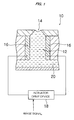
- Fig. 1 is a principal cross-sectional diagram showing an approximate view of one embodiment of a droplet discharging apparatus relating to the present invention.
- the droplet discharging apparatus 10 according to the present embodiment comprises: a pressure chamber 12 for accommodating a liquid to be discharged; a nozzle 14 for discharging a liquid provided in one end of the pressure chamber 12, as a droplet; an actuator 16 for changing the volume of the pressure chamber 12 provided in the wall of the pressure chamber 12; an actuator drive device 18 for applying a drive waveform to an actuator 16 in accordance with an image signal; and a liquid supply passage 20, or the like, connected to a liquid tank (not illustrated), for supplying the liquid to the pressure chamber 12 from the liquid tank; or the like.
- the actuator 16 forming a device for generating a liquid discharging pressure for discharging a liquid from the nozzle 14, as a droplet, by changing the volume of the pressure chamber 12 is constituted by a movable element (piezoelectric element) disposed on the wall of the pressure chamber 12 in such a manner that it is driven in a shearing mode, but the actuator 16 is not limited to being a piezoelectric element of this kind and it is possible, for example, to provide a piezoelectric element in the other end portion of the pressure chamber 12 opposing the nozzle 14, causing the volume of the pressure chamber 12 to change by means of deformation of the piezo element, and hence causing a liquid to be discharged as a droplet from the nozzle 14.
- the actuator driving means 18 applies a prescribed drive waveform to the actuator 16, on the basis of an input image signal, as described hereinafter, hence causing the movable part of the actuator 16 to move, whereby the volume of the pressure chamber 12 is caused to change and the liquid is discharged as a droplet from the nozzle 14.
- the liquid used in the present embodiment is a liquid of high viscosity. This liquid with high viscosity does not cause the meniscus face to vibrate, and does not have a so-called natural period, and more specifically, it is specified by the conditions described below.
- the droplet discharging apparatus discharges a liquid as a minute droplet, and at a satisfactory discharge speed, in conditions where the viscosity of the liquid is high and the meniscus surface does not vibrate naturally, and next, the conditions whereby there is no vibration of the meniscus surface are described.
- Fig. 2A is a simplified diagram for facilitating the description of the aforementioned pressure chamber 12 and the nozzle 14, each being represented respectively as round bars.
- the length of the pressure chamber 12 is indicated as l 1
- the surface area of the base of the pressure chamber 12 is indicated as S
- the length of the nozzle 14 is indicated as l 0
- the surface area of the base of the nozzle 14 is indicated as A.
- the compliance of the pressure chamber 12 is indicated as C
- the inertance of the liquid flow passage is indicated as L
- the resistance in the nozzle section due to the viscosity of the liquid is indicated as R
- the density of the discharged liquid is indicated as r
- the viscosity coefficient of the discharged liquid is indicated as ⁇
- the transmission rate of the pressure wave transmitted through the pressure chamber is indicated as c.
- T 4 ⁇ L 4L C - R 2 .
- T does not exist as a real number, in other words, 4L / C - R 2 ⁇ 0.
- This inequality expression (1) states the condition whereby the meniscus surface of the liquid does not vibrate at all.
- the inequality expression (1) is effected, the meniscus surface of the liquid is damped completely, without vibrating at all. Consequently, in this case, the meniscus surface does not vibrate, even if a sharp impetus is applied.
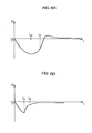
- Fig. 4A shows this solution v in the form of a graph.
- t a 1 2 ⁇ ln ⁇ + ⁇ ⁇ - ⁇ .
- t b 1 2 ⁇ ln ⁇ + ⁇ ⁇ - ⁇ 2 .
- a liquid of high viscosity is discharged as a minute droplet, at a satisfactory discharge speed, under the conditions expressed by the inequality expression (1) above whereby the meniscus surface does not vibrate.
- a drive waveform applied to the actuator 16 by the actuator drive device 18 in order to achieve discharge of this kind is described.
- Fig. 5 shows a comparison of the drive waveform applied to the actuator 16, and the volume displacement rate v of the liquid at the meniscus surface.
- the drive waveform according to the present embodiment is constituted by a first drive waveform W1, a second drive waveform W2, a third drive waveform W3 and a fourth drive waveform W4, and comprises hold sections U1, U2 in which the drive voltage is held, between the first drive waveform W1 and the second drive waveform W2, and between the second drive waveform W2 and the third drive waveform W3, respectively.
- the first drive waveform W1 serves to suction the liquid in order to draw the meniscus surface of the liquid in the nozzle 14 towards the inside.
- the second drive waveform W2 serves to push the liquid from the nozzle 14, by applying pressure to the liquid in the pressure chamber 12 in order to create a liquid column, and hence cause the liquid to be discharged from the nozzle 14 as a droplet.
- the third drive waveform W3 serves to create a minute droplet by breaking apart the liquid column created by pushing the liquid from the nozzle 14.
- the fourth drive waveform W4 serves to return the meniscus surface rapidly to its initial state, after breaking apart.
- the first drive waveform W1 is applied to the actuator 16.
- the downward direction indicates that the liquid in the nozzle 14 is suctioned towards the pressure chamber 12
- the upward direction indicates that the liquid in the pressure chamber 12 is, conversely, pushed out from the nozzle 14.
- the graph of the drive waveform indicates change in the voltage applied to the actuator 16, but the change in the voltage corresponds with change in the surface of the liquid, and hence this graph can also be regarded as indicating the displacement of the surface of the liquid, at the same time.
- the drive waveform is started by applying the first drive waveform W1, but it is not necessarily required to apply this first drive waveform W1. It is also possible to apply the second drive waveform W2 from the prescribed time t 2 , directly, without applying the first drive waveform W1.
- the voltage is held at a constant value (hold section U2).
- the rate of volume displacement is also zero.
- a third drive waveform W3 is applied and the voltage is reduced.
- the rate of volume displacement is a constant negative value, namely v 3 . Due to this third drive waveform W3, the liquid is pulled and the liquid column is broken apart, thereby forming a liquid droplet, which is projected towards the recording medium.
- the fourth drive waveform W4 reduces the voltage from E 3 until the reference voltage E 0 .
- the rate of volume displacement is negative and the absolute value thereof is a large value.
- the actuator 16 is driven by a drive waveform of this kind by means of an actuator drive device 18, and a liquid with high viscosity is discharged as a minute droplet at a satisfactory speed.
- a drive waveform of this kind by means of an actuator drive device 18, and a liquid with high viscosity is discharged as a minute droplet at a satisfactory speed.
- the time period t 2 from the start of application of the first drive waveform W1 until the start of the second drive waveform W2 is determined as follows.
- the rate v of displacement of the surface of the liquid decreases in the range of 0 ⁇ t ⁇ t a , and hence the acceleration is negative, whereas when t > t a , the rate of displacement v starts to increase, and the acceleration becomes positive. Moreover, it is considered to be more efficient if a pressing force is applied and the liquid is discharged as a droplet when the acceleration of the displacement of the surface of the liquid is positive.
- the acceleration of the displacement of the surface of the liquid is a maximum value during this.
- the acceleration reaches a maximum at the turning point t b . Therefore, desirably, the time period t 2 until the liquid starts to be pushed, immediately after the liquid starts to be suctioned, is indicated as the position of the turning point t b , where the acceleration of the displacement of the liquid surface becomes a maximum.
- the liquid is pushed out at a time after the point t a at which the rate of volume displacement of the liquid reaches a maximum, and more desirably, the liquid is pushed out at a time corresponding to the turning point t b of the rate of displacement, where the acceleration of the volume displacement of the liquid reaches a maximum.
- the third drive waveform W3 is desirably set in such a manner that the gradient thereof in the graph shown in Fig. 5, is lower in absolute terms than the gradient of the second drive waveform W2. More specifically, in terms of the graph of the volume displacement rate at the bottom of Fig. 5, the rate of volume displacement v 3 corresponding to the third drive waveform W3 is designed to be lower in absolute terms than the rate of volume displacement v 2 corresponding to the second drive waveform W2, as indicated as the following inequality expression (4): v 2 > v 3 .
- the relationship between the third drive waveform W3 and the fourth drive waveform W4 is set in such a manner that, in the gradient of the graph in Fig. 5, the gradient of the fourth drive waveform W4 is greater in absolute terms than the gradient of the third drive waveform W3. More specifically, in terms of the graph of the volume displacement rate at the bottom of Fig. 5, desirably, the rate of volume displacement v 3 corresponding to the third drive waveform W3 is greater in absolute terms than the rate of volume displacement v 4 corresponding to the fourth drive waveform W4, as indicated as the following inequality expression (5): v 4 > v 3 .
- the meniscus surface of the liquid can be stabilized and returned to its initial state, after the liquid column has been broken apart and a liquid droplet has been discharged.
- a conventional liquid of low viscosity since the surface of the liquid vibrates, if it sought to stabilize the liquid rapidly by constricting it, this may conversely cause additional vibration and not lead to the desired stabilization, and hence the intrinsic vibration of the liquid surface must be taken into account when determining the time at which the liquid is to be constricted, but in the present case, the liquid is of high viscosity and does not vibrate, and hence it is desirable to constrict the liquid as rapidly as possible.
- the time period between the third drive waveform W3 and the fourth drive waveform W4 is as short as possible.
- the conditions are set whereby no vibration in the liquid surface occurs when a liquid of high viscosity is used, then there are absolutely no restrictions relating to time, and hence time does not need to be taken into account and the surface of the liquid can be stabilized rapidly by applying the fourth drive waveform W4 for constricting the liquid, straight away. Consequently, it is possible to perform the next printing operation, in an immediately subsequent fashion, and it is possible to increase the printing speed.
- the time period t 4 - t 3 of the hold section U2 during which the voltage is held, between the second drive waveform W2 and the third drive waveform W3, is as short as possible, in order to form a minute droplet. If this time period is long, then the discharged droplet will become larger. Depending on the circumstances, this time period may be set to zero, and the hold section U2 omitted altogether.
- the third drive waveform W3 is set so as to have a lower gradient in absolute terms, in the graph shown in Fig. 4, than the gradient of the second drive waveform W2, but in order to increase the breaking effect and facilitate the creation of minute droplets, it is desirable that the gradient of the third drive waveform W3 is as high as possible, whilst satisfying the condition of being lower than that of the second drive waveform W2.
- relating to the third drive waveform W3 should be as rapid (large) as possible.
Landscapes
- Particle Formation And Scattering Control In Inkjet Printers (AREA)
- Electroluminescent Light Sources (AREA)
- Application Of Or Painting With Fluid Materials (AREA)
Applications Claiming Priority (2)
| Application Number | Priority Date | Filing Date | Title |
|---|---|---|---|
| JP2003333060 | 2003-09-25 | ||
| JP2003333060 | 2003-09-25 |
Publications (3)
| Publication Number | Publication Date |
|---|---|
| EP1518679A2 true EP1518679A2 (fr) | 2005-03-30 |
| EP1518679A3 EP1518679A3 (fr) | 2007-06-20 |
| EP1518679B1 EP1518679B1 (fr) | 2008-09-10 |
Family
ID=34191478
Family Applications (1)
| Application Number | Title | Priority Date | Filing Date |
|---|---|---|---|
| EP04022812A Expired - Lifetime EP1518679B1 (fr) | 2003-09-25 | 2004-09-24 | Méthode et appareil d'éjection de goutellettes |
Country Status (3)
| Country | Link |
|---|---|
| US (1) | US7137680B2 (fr) |
| EP (1) | EP1518679B1 (fr) |
| DE (1) | DE602004016436D1 (fr) |
Cited By (4)
| Publication number | Priority date | Publication date | Assignee | Title |
|---|---|---|---|---|
| EP1839868A1 (fr) * | 2006-03-30 | 2007-10-03 | Brother Kogyo Kabushiki Kaisha | Tête à jet d'encre |
| EP2098371A1 (fr) * | 2008-03-07 | 2009-09-09 | Seiko Epson Corporation | Procédé d'éjection de liquide, tête d'éjection de liquide et appareil d'éjection de liquide |
| EP2098370A1 (fr) * | 2008-03-07 | 2009-09-09 | Seiko Epson Corporation | Procédé d'éjection de liquide, tête d'éjection de liquide et appareil d'éjection de liquide |
| EP2105301A1 (fr) * | 2008-03-26 | 2009-09-30 | Seiko Epson Corporation | Procédé de décharge de liquide, tête de décharge de liquide, et appareil de décharge de liquide |
Families Citing this family (5)
| Publication number | Priority date | Publication date | Assignee | Title |
|---|---|---|---|---|
| US7140554B2 (en) | 2002-04-09 | 2006-11-28 | Seiko Epson Corporation | Liquid ejection head |
| JP2011073245A (ja) * | 2009-09-30 | 2011-04-14 | Seiko Epson Corp | 液体吐出ヘッド、及び、液体吐出装置 |
| JP2012136010A (ja) | 2010-12-06 | 2012-07-19 | Seiko Epson Corp | 液体噴射ヘッド、及び、液体噴射装置 |
| JP5944652B2 (ja) * | 2011-11-29 | 2016-07-05 | 理想科学工業株式会社 | インクジェット記録装置のインク液滴吐出方法 |
| JP7196652B2 (ja) * | 2018-03-08 | 2022-12-27 | 株式会社リコー | インクセット、画像形成装置、及び画像形成方法 |
Citations (2)
| Publication number | Priority date | Publication date | Assignee | Title |
|---|---|---|---|---|
| JPH11170515A (ja) | 1997-12-16 | 1999-06-29 | Brother Ind Ltd | インク滴噴射方法及びその装置 |
| JPH11227203A (ja) | 1997-12-10 | 1999-08-24 | Brother Ind Ltd | インク滴噴射方法及びその装置 |
Family Cites Families (8)
| Publication number | Priority date | Publication date | Assignee | Title |
|---|---|---|---|---|
| JPS585269A (ja) * | 1981-07-02 | 1983-01-12 | Seiko Epson Corp | インクジエツト印刷装置 |
| JP2624772B2 (ja) | 1988-04-30 | 1997-06-25 | キヤノン株式会社 | インクジェット記録方法 |
| JPH01278358A (ja) | 1988-04-30 | 1989-11-08 | Canon Inc | インクジェット記録方式 |
| US5371520A (en) * | 1988-04-28 | 1994-12-06 | Canon Kabushiki Kaisha | Ink jet recording apparatus with stable, high-speed droplet ejection |
| JP2593940B2 (ja) | 1988-10-14 | 1997-03-26 | 富士電機株式会社 | インクジェット記録ヘッドの駆動方法 |
| JP2967739B2 (ja) | 1996-12-17 | 1999-10-25 | 日本電気株式会社 | インクジェット式プリントヘッドの駆動方法及び装置 |
| DE60031316T2 (de) * | 1999-01-29 | 2007-04-12 | Seiko Epson Corp. | Tintenstrahlaufzeichnungsvorrichtung |
| JP3896830B2 (ja) * | 2001-12-03 | 2007-03-22 | 富士ゼロックス株式会社 | 液滴吐出ヘッドおよびその駆動方法並びに液滴吐出装置 |
-
2004
- 2004-09-24 US US10/948,126 patent/US7137680B2/en not_active Expired - Fee Related
- 2004-09-24 EP EP04022812A patent/EP1518679B1/fr not_active Expired - Lifetime
- 2004-09-24 DE DE602004016436T patent/DE602004016436D1/de not_active Expired - Lifetime
Patent Citations (2)
| Publication number | Priority date | Publication date | Assignee | Title |
|---|---|---|---|---|
| JPH11227203A (ja) | 1997-12-10 | 1999-08-24 | Brother Ind Ltd | インク滴噴射方法及びその装置 |
| JPH11170515A (ja) | 1997-12-16 | 1999-06-29 | Brother Ind Ltd | インク滴噴射方法及びその装置 |
Cited By (8)
| Publication number | Priority date | Publication date | Assignee | Title |
|---|---|---|---|---|
| EP1839868A1 (fr) * | 2006-03-30 | 2007-10-03 | Brother Kogyo Kabushiki Kaisha | Tête à jet d'encre |
| US7611229B2 (en) | 2006-03-30 | 2009-11-03 | Brother Kogyo Kabushiki Kaisha | Inkjet head |
| EP2098371A1 (fr) * | 2008-03-07 | 2009-09-09 | Seiko Epson Corporation | Procédé d'éjection de liquide, tête d'éjection de liquide et appareil d'éjection de liquide |
| EP2098370A1 (fr) * | 2008-03-07 | 2009-09-09 | Seiko Epson Corporation | Procédé d'éjection de liquide, tête d'éjection de liquide et appareil d'éjection de liquide |
| CN102139562A (zh) * | 2008-03-07 | 2011-08-03 | 精工爱普生株式会社 | 液体喷射方法、液体喷射头、以及液体喷射装置 |
| US8061819B2 (en) | 2008-03-07 | 2011-11-22 | Seiko Epson Corporation | Liquid ejecting method, liquid ejecting head, and liquid ejecting apparatus |
| US8382256B2 (en) | 2008-03-07 | 2013-02-26 | Seiko Epson Corporation | Method, head and apparatus for ejecting viscous liquids |
| EP2105301A1 (fr) * | 2008-03-26 | 2009-09-30 | Seiko Epson Corporation | Procédé de décharge de liquide, tête de décharge de liquide, et appareil de décharge de liquide |
Also Published As
| Publication number | Publication date |
|---|---|
| US7137680B2 (en) | 2006-11-21 |
| EP1518679B1 (fr) | 2008-09-10 |
| DE602004016436D1 (de) | 2008-10-23 |
| EP1518679A3 (fr) | 2007-06-20 |
| US20050099457A1 (en) | 2005-05-12 |
Similar Documents
| Publication | Publication Date | Title |
|---|---|---|
| EP0541129B1 (fr) | Méthode et appareil pour la commande d'une tête d'enregistrement à jet d'encre | |
| US6312077B1 (en) | Ink jet printer and ink jet printing method | |
| US6971733B2 (en) | Ink jet recording apparatus | |
| JP4664092B2 (ja) | インクジェットプリントヘッドの駆動方法 | |
| EP0765750B1 (fr) | Methode permettant de commander une tete a jet d'encre | |
| JPH09327909A (ja) | インクジェット式記録装置による記録方法、及び前記記録方法に適した記録ヘッド | |
| JP2593940B2 (ja) | インクジェット記録ヘッドの駆動方法 | |
| EP0858892B1 (fr) | Imprimante à jet d'encre | |
| JP2003001821A (ja) | インクジェット記録装置及びインクジェット記録方法 | |
| EP0575204A2 (fr) | Méthode de commande d'un jet d'encre pour réaliser une haute qualité d'impression et un haut débit d'impression | |
| EP1518679B1 (fr) | Méthode et appareil d'éjection de goutellettes | |
| JP3679865B2 (ja) | インクジェット式記録装置 | |
| JP2000117993A (ja) | インクジェット式記録装置 | |
| JP2000203020A (ja) | インクジェット式プリンタ用ヘッドの駆動装置および方法 | |
| JPH05338165A (ja) | 液体噴射記録ヘッドの駆動方法 | |
| JP5125004B2 (ja) | 微小インク滴の吐出方法 | |
| JP3525616B2 (ja) | インクジェット記録装置及びその制御方法 | |
| JP3801605B2 (ja) | 液滴吐出方法及び装置 | |
| JP3755569B2 (ja) | インクジェット記録ヘッドの駆動方法及びその回路 | |
| JP2002326357A (ja) | インクジェット式記録ヘッドの駆動方法 | |
| JPH0516359A (ja) | 液体噴射記録ヘツドの駆動方法 | |
| JP2006027036A (ja) | インクジェットプリントヘッドの駆動方法 | |
| JPH05318731A (ja) | インクジェット式記録ヘッドの駆動方法、及びその装置 | |
| JP2000263775A (ja) | インクジェット式記録装置 | |
| JP2002036553A (ja) | 液体噴射記録装置 |
Legal Events
| Date | Code | Title | Description |
|---|---|---|---|
| PUAI | Public reference made under article 153(3) epc to a published international application that has entered the european phase |
Free format text: ORIGINAL CODE: 0009012 |
|
| AK | Designated contracting states |
Kind code of ref document: A2 Designated state(s): AT BE BG CH CY CZ DE DK EE ES FI FR GB GR HU IE IT LI LU MC NL PL PT RO SE SI SK TR |
|
| AX | Request for extension of the european patent |
Extension state: AL HR LT LV MK |
|
| RAP1 | Party data changed (applicant data changed or rights of an application transferred) |
Owner name: FUJIFILM CORPORATION |
|
| PUAL | Search report despatched |
Free format text: ORIGINAL CODE: 0009013 |
|
| AK | Designated contracting states |
Kind code of ref document: A3 Designated state(s): AT BE BG CH CY CZ DE DK EE ES FI FR GB GR HU IE IT LI LU MC NL PL PT RO SE SI SK TR |
|
| AX | Request for extension of the european patent |
Extension state: AL HR LT LV MK |
|
| 17P | Request for examination filed |
Effective date: 20070807 |
|
| AKX | Designation fees paid |
Designated state(s): DE FR GB |
|
| GRAP | Despatch of communication of intention to grant a patent |
Free format text: ORIGINAL CODE: EPIDOSNIGR1 |
|
| GRAS | Grant fee paid |
Free format text: ORIGINAL CODE: EPIDOSNIGR3 |
|
| GRAA | (expected) grant |
Free format text: ORIGINAL CODE: 0009210 |
|
| AK | Designated contracting states |
Kind code of ref document: B1 Designated state(s): DE FR GB |
|
| REG | Reference to a national code |
Ref country code: GB Ref legal event code: FG4D |
|
| REF | Corresponds to: |
Ref document number: 602004016436 Country of ref document: DE Date of ref document: 20081023 Kind code of ref document: P |
|
| PLBE | No opposition filed within time limit |
Free format text: ORIGINAL CODE: 0009261 |
|
| STAA | Information on the status of an ep patent application or granted ep patent |
Free format text: STATUS: NO OPPOSITION FILED WITHIN TIME LIMIT |
|
| 26N | No opposition filed |
Effective date: 20090611 |
|
| REG | Reference to a national code |
Ref country code: FR Ref legal event code: PLFP Year of fee payment: 12 |
|
| PGFP | Annual fee paid to national office [announced via postgrant information from national office to epo] |
Ref country code: GB Payment date: 20150923 Year of fee payment: 12 Ref country code: DE Payment date: 20150916 Year of fee payment: 12 |
|
| PGFP | Annual fee paid to national office [announced via postgrant information from national office to epo] |
Ref country code: FR Payment date: 20150629 Year of fee payment: 12 |
|
| REG | Reference to a national code |
Ref country code: DE Ref legal event code: R119 Ref document number: 602004016436 Country of ref document: DE |
|
| GBPC | Gb: european patent ceased through non-payment of renewal fee |
Effective date: 20160924 |
|
| REG | Reference to a national code |
Ref country code: FR Ref legal event code: ST Effective date: 20170531 |
|
| PG25 | Lapsed in a contracting state [announced via postgrant information from national office to epo] |
Ref country code: DE Free format text: LAPSE BECAUSE OF NON-PAYMENT OF DUE FEES Effective date: 20170401 Ref country code: FR Free format text: LAPSE BECAUSE OF NON-PAYMENT OF DUE FEES Effective date: 20160930 Ref country code: GB Free format text: LAPSE BECAUSE OF NON-PAYMENT OF DUE FEES Effective date: 20160924 |