EP1518660B1 - Verfahren und Vorrichtung zur Beschichtung von Bauteilen - Google Patents
Verfahren und Vorrichtung zur Beschichtung von Bauteilen Download PDFInfo
- Publication number
- EP1518660B1 EP1518660B1 EP04020977A EP04020977A EP1518660B1 EP 1518660 B1 EP1518660 B1 EP 1518660B1 EP 04020977 A EP04020977 A EP 04020977A EP 04020977 A EP04020977 A EP 04020977A EP 1518660 B1 EP1518660 B1 EP 1518660B1
- Authority
- EP
- European Patent Office
- Prior art keywords
- pallet
- components
- coating
- coated
- separated
- Prior art date
- Legal status (The legal status is an assumption and is not a legal conclusion. Google has not performed a legal analysis and makes no representation as to the accuracy of the status listed.)
- Expired - Lifetime
Links
- 238000000576 coating method Methods 0.000 title claims abstract description 25
- 239000011248 coating agent Substances 0.000 title claims abstract description 21
- 238000000034 method Methods 0.000 title claims abstract description 19
- 239000011888 foil Substances 0.000 claims description 8
- 238000007789 sealing Methods 0.000 claims description 3
- 230000008021 deposition Effects 0.000 claims 1
- 239000000047 product Substances 0.000 description 4
- 125000006850 spacer group Chemical group 0.000 description 4
- 238000000926 separation method Methods 0.000 description 2
- 239000000853 adhesive Substances 0.000 description 1
- 230000001070 adhesive effect Effects 0.000 description 1
- 238000013459 approach Methods 0.000 description 1
- 239000006227 byproduct Substances 0.000 description 1
- 230000002349 favourable effect Effects 0.000 description 1
- 238000010438 heat treatment Methods 0.000 description 1
- 230000002093 peripheral effect Effects 0.000 description 1
- 238000004904 shortening Methods 0.000 description 1
Images
Classifications
-
- B—PERFORMING OPERATIONS; TRANSPORTING
- B29—WORKING OF PLASTICS; WORKING OF SUBSTANCES IN A PLASTIC STATE IN GENERAL
- B29C—SHAPING OR JOINING OF PLASTICS; SHAPING OF MATERIAL IN A PLASTIC STATE, NOT OTHERWISE PROVIDED FOR; AFTER-TREATMENT OF THE SHAPED PRODUCTS, e.g. REPAIRING
- B29C51/00—Shaping by thermoforming, i.e. shaping sheets or sheet like preforms after heating, e.g. shaping sheets in matched moulds or by deep-drawing; Apparatus therefor
- B29C51/26—Component parts, details or accessories; Auxiliary operations
- B29C51/44—Removing or ejecting moulded articles
- B29C51/445—Removing or ejecting moulded articles from a support after moulding, e.g. by cutting
-
- B—PERFORMING OPERATIONS; TRANSPORTING
- B29—WORKING OF PLASTICS; WORKING OF SUBSTANCES IN A PLASTIC STATE IN GENERAL
- B29C—SHAPING OR JOINING OF PLASTICS; SHAPING OF MATERIAL IN A PLASTIC STATE, NOT OTHERWISE PROVIDED FOR; AFTER-TREATMENT OF THE SHAPED PRODUCTS, e.g. REPAIRING
- B29C51/00—Shaping by thermoforming, i.e. shaping sheets or sheet like preforms after heating, e.g. shaping sheets in matched moulds or by deep-drawing; Apparatus therefor
- B29C51/26—Component parts, details or accessories; Auxiliary operations
- B29C51/261—Handling means, e.g. transfer means, feeding means
-
- B—PERFORMING OPERATIONS; TRANSPORTING
- B29—WORKING OF PLASTICS; WORKING OF SUBSTANCES IN A PLASTIC STATE IN GENERAL
- B29C—SHAPING OR JOINING OF PLASTICS; SHAPING OF MATERIAL IN A PLASTIC STATE, NOT OTHERWISE PROVIDED FOR; AFTER-TREATMENT OF THE SHAPED PRODUCTS, e.g. REPAIRING
- B29C63/00—Lining or sheathing, i.e. applying preformed layers or sheathings of plastics; Apparatus therefor
- B29C63/02—Lining or sheathing, i.e. applying preformed layers or sheathings of plastics; Apparatus therefor using sheet or web-like material
-
- Y—GENERAL TAGGING OF NEW TECHNOLOGICAL DEVELOPMENTS; GENERAL TAGGING OF CROSS-SECTIONAL TECHNOLOGIES SPANNING OVER SEVERAL SECTIONS OF THE IPC; TECHNICAL SUBJECTS COVERED BY FORMER USPC CROSS-REFERENCE ART COLLECTIONS [XRACs] AND DIGESTS
- Y10—TECHNICAL SUBJECTS COVERED BY FORMER USPC
- Y10T—TECHNICAL SUBJECTS COVERED BY FORMER US CLASSIFICATION
- Y10T156/00—Adhesive bonding and miscellaneous chemical manufacture
- Y10T156/19—Delaminating means
Definitions
- the invention relates to a method and a device for vozugêt three-dimensional coating of components, in particular furniture fronts, with a film, wherein the components are in a range which is rotated after the coating process in a rotary inverter by about 180 °, so that the coated and over their common foil related components fall out of the pallet and can be separated.
- the coating is usually carried out in a press, where the components - optionally pretreated with an adhesive - are connected to the film under the action of pressure and heat. So that several workpieces can be simultaneously transported to the press, coated there and then moved out, the workpieces are located in a common pallet. From the pallet, they do not only have to be removed after the coating process, but also, above all, cut out of the common film joining them.
- the pallet moves into a rotary turner in which a height-adjustable conveyor belt is arranged.
- This conveyor belt approaches the components from above and clamps them in the pallet. This is followed by rotation through 180 °, so that the components then lie with their foil down on the conveyor belt.
- the conveyor belt is then lowered, causing the contiguous components to fall out of the pallet. They are then moved out longitudinally or transversely out of the rotary turner and cut out of the foil on a cut-out table.
- the empty pallet is turned back again and driven back to a loading station, where it is again filled with the components to be coated.
- a loading station where it is again filled with the components to be coated.
- the entire coating system therefore requires a relatively large amount of space, and the expenditure on equipment is high.
- EP 0 835 739 describes the turning of a component during the passage of a printing system in order to be able to press it from both sides by means of a printing unit.
- EP 1 228 852 shows a turner for a deep drawing tool.
- the present invention has for its object to realize the known coating method and the associated device in a more compact manner than before. At the same time, the invention should be characterized by cost-effective design and efficient operation.
- This object is achieved in that worked with a double-sided assignable range and dispense with the previous reverse rotation of the pallet after the component removal.
- the two-sided occupancy possibility of the pallet both at its top as well as on its underside and their resulting two-sided process capability in the press not only results in a shortening of the cycle time, because the previously necessary reverse rotation of the pallet is eliminated. Rather, the invention also offers the possibility to dispense with the hitherto necessary return transport of the pallet to the charging station and to occupy the pallet directly in the turntable itself or a next lying Legetisch with new components. In addition, only needs to be worked with a single pallet, whereas so far mostly several pallets were in circulation. As a result, the operation is considerably streamlined and at the same time reduces the expenditure on equipment and the space required for this purpose.
- the separation of the coated components after turning can be done outside the turntable. It is particularly useful if the separation takes place directly in the turntable itself, either after the pallet has been moved to a position that does not interfere with the cutting or after it has moved back into the press newly occupied.
- the coated components may as before fall on a lowerable surface. According to the invention, however, this pad remains in the turntable and conveys the components only in a favorable for cutting the components working height after the empty pallet has been moved out of this area.
- said pad is arranged in such a height adjustable in the rotary inverter that it also serves to clamp the coming of the coating press components before and during turning.
- the device for carrying out the method according to the invention is characterized in that working with a pallet, which can be occupied and sealed both on the upper side as well as on the underside with components. Based on the previous positioning of the seal on the top, it is advisable to provide the pallet with an additional, similar seal at the bottom and form them substantially symmetrical bottom and top, so that both sides can be equally well occupied.
- Said pad is suitably combined with a conveying device which allows the coated products to be moved forwards or to the side in cycles, so that they can be gradually cut and removed by the operator from the edge.
- the constructive design of the pallet is practically characterized in that its frame not only as previously up, but equally also projecting down.
- the coating press has to have adapted thereto a lower press table, which is stepped down in the range of the pallet frame so that it can support the components carrying the pallet base from below.
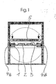
- Fig. 1 shows a pallet 1, which is occupied on its upper side with a plurality of coated components 2.
- the components 2 are located on spacers with a smaller cross-section on the pallet, so that the coating film 3 not only on the upper side, but also adheres to the lateral edge surfaces to the lower edge of the components.
- an automatic support system built into the coating press can be used.
- the pallet 1 is mounted horizontally movable on guide rails 4a and 4b so that they can be moved in or out of the rotary turner.
- the guide rails 4a and 4b are pivotally mounted about a common, horizontal central axis in the rotary inverter, so that the pallet 1 can be turned from the drawn in Fig. 1 position by 180 ° in the position shown in FIG.
- a plate 5 is arranged parallel to the pallet 1 in the rotary turner. This plate 5 is mounted vertically adjustable in the rotary inverter and can at the same time join the said rotary movement of the pallet 1.
- the pallet 1 with the freshly coated components 2 is brought in from the press into the rotary turner.
- the plate 5 is located in a position spaced above the pallet 1. This state is shown in Fig. 1.
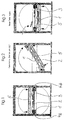
- the plate 5 moves down until it rests against the top of the pallet 1 and / or its coated components 2. This is followed by the turning process, as shown in Fig. 2 after a rotation angle of about 150 °. Towards the end of this turning process, the workpieces 2 with their common foil 3 fall out of the pallet 1 and then lie on the plate 5, which now no longer functions as a cover, but as a support.
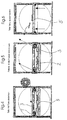
- the pallet If the pallet is completely occupied, it moves back into the coating press, not shown, and in the vacant space of the rotary inverter the plate 5 moves upwards with the coated components 2, cf. Fig. 5 and 6.
- the components which are glued to the underside and the side edges with the film 3, can now be easily cut out of the film and removed.
- the coating of the next batch takes place in the press.
- the cutting of the coated components begins at the edge, in Figure 6 at the left edge of the plate 5.
- the plate 5 is for this purpose equipped with a conveyor belt 6, which moves the products cyclically to the left, so that they comfortably at the edge of Plate 5 can be cut out and separated.
- the operator adjusts the conveyor belt 6 again to move the next product row to the edge.
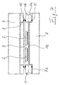
- FIG. 7 shows the pallet according to the invention in the process chamber of the coating press. As before, it consists of a perforated pallet base 1a and a peripheral upper frame 1b, but according to the invention is provided with a similar lower frame 1c. Both frames carry on their side facing away from the pallet base 1a a circumferential seal 1b 'and 1c'. As a result, the palette has top and bottom functional occupancy fields and is process-compatible on both sides.
- the lower press table 7 carrying the pallet has a contour adapted to the pallet cross section, namely an edge-side step 7a for receiving the lower pallet frame 1c.
- the central part of the lower press table 7, however, projects upwards and supports the pallet base 1a, so that it does not bend appreciably during the coating process, in particular during the pressurization of the film 3.
- the components to be coated 2 are spacers, so that they can be optimally coated with the film 3 not only on the top, but also on their vertical side surfaces.
- spacers it is of course also within the scope of the invention to provide a PIN system in the pallet or in the lower press table to lift the components 2 from the pallet floor 1a.
- Figure 7 still shows the usual upper sealing frame 8, which presses and seals the film 3 against the upper pallet frame 1b and the heating plate 9, which is moved in close contact with the top of the sealing frame 8.
- the process chamber corresponds to the usual structure.
- the invention is characterized by the double-sided usable range by a much cheaper and more efficient operation.
Landscapes
- Engineering & Computer Science (AREA)
- Mechanical Engineering (AREA)
- Application Of Or Painting With Fluid Materials (AREA)
- Automatic Assembly (AREA)
- Coating Apparatus (AREA)
- Pallets (AREA)
- Spray Control Apparatus (AREA)
- Physical Vapour Deposition (AREA)
Description
- Die Erfindung betrifft ein Verfahren und eine Vorrichtung zur vozugsweise dreidimensionalen Beschichtung von Bauteilen, insbesondere Möbelfronten, mit einer Folie, wobei die Bauteile in einer Palette liegen, die nach dem Beschichtungsvorgang in einem Drehwender um etwa 180° gedreht wird, so dass die beschichteten und über ihre gemeinsame Folie zusammenhängenden Bauteile aus der Palette herausfallen und vereinzelt werden können.
- Die Beschichtung erfolgt üblicherweise in einer Presse, wo die Bauteile - gegebenenfalls mit einem Klebstoff vorbehandelt - unter Einwirkung von Druck und Wärme mit der Folie verbunden werden. Damit mehrere Werkstücke gleichzeitig zur Presse transportiert, dort beschichtet und anschließend herausgefahren werden können, liegen die Werkstücke in einer gemeinsamen Palette. Aus dieser Palette müssen sie nach dem Beschichtungsvorgang nicht nur entnommen, sondern vor allem auch aus der sie verbindenden gemeinsamen Folie herausgeschnitten werden.
- Zum Herausschneiden der beschichteten Bauteile fährt die Palette in einen Drehwender, in dem ein höhenverstellbares Transportband angeordnet ist. Dieses Transportband fährt von oben an die Bauteile heran und verklemmt sie in der Palette. Hierauf erfolgt die Drehung um 180°, so dass die Bauteile anschließend mit ihrer Folie nach unten auf dem Transportband liegen. Das Transportband wird dann abgesenkt, wodurch die zusammenhängenden Bauteile aus der Palette herausfallen. Sie werden dann längs oder quer aus dem Drehwender herausgefahren und auf einem Ausschneidetisch aus der Folie ausgeschnitten.
- Sobald die Charge aus der Palette herausgefallen ist, wird die leere Palette wieder zurückgedreht, und zurück in eine Ladestation gefahren, wo sie erneut mit den zu beschichtenden Bauteilen belegt wird. Dazu ist es notwendig, die Palette entweder nach unten abzusenken und sie unter der Presse hindurch zurückzufahren oder sie seitlich um die Presse herumzutransportieren. Man braucht also auf der Eingabeseite der Presse eine Ladestation, auf der Ausgabeseite einen Drehwender und einen Ausschneidetisch. Die gesamte Beschichtungsanlage benötigt daher relativ viel Aufstellungsplatz, auch der apparative Aufwand ist hoch.
- Die EP 0 835 739 beschreibt das Wenden eines Bauteils wahrend des Durchlaufs einer Bedruckanlage, um es von beiden Seiten mittels einer Druckeinheit bedruchen zu können.
- EP 1 228 852 zeigt einen Wender für ein Tiefziehwerkzeug.
- Der vorliegenden Erfindung liegt die Aufgabe zugrunde, das bekannte Beschichtungsverfahren und die zugehörige Vorrichtung in kompakterer Weise als bisher zu realisieren. Zugleich soll sich die Erfindung durch kostengünstigen Aufbau und rationelle Betriebsweise auszeichnen.
- Diese Aufgabe wird erfindungsgemäß dadurch gelöst, dass mit einer doppelseitig belegbaren Palette gearbeitet und auf die bisherige Rückdrehung der Palette nach der Bauteil-Entnahme verzichtet wird.
- Die beidseitige Belegungsmöglichkeit der Palette sowohl an ihrer Oberseite wie auch an ihrer Unterseite und ihre daraus resultierende beidseitige Prozesstauglichkeit in der Presse ergibt nicht nur eine Verkürzung der Taktzeit, weil die bisher notwendige Rückdrehung der Palette entfällt. Vielmehr bietet die Erfindung auch die Möglichkeit, auf den bisher notwendigen Rücktransport der Palette zur Ladestation zu verzichten und die Palette unmittelbar im Drehwender selbst oder einem daneben angeordneten Legetisch mit neuen Bauteilen zu belegen. Außerdem braucht nur noch mit einer einzigen Palette gearbeitet zu werden, wogegen bisher meist mehrere Paletten im Umlauf waren. Dadurch wird der Betriebsablauf erheblich rationalisiert und gleichzeitig der apparative Aufwand und der hierfür notwendige Platzbedarf reduziert.
- Die Vereinzelung der beschichteten Bauteile nach dem Wenden kann außerhalb des Drehwenders erfolgen. Besonders zweckmäßig ist es aber, wenn die Vereinzelung direkt im Drehwender selbst stattfindet, entweder nachdem die Palette in eine das Ausschneiden nicht behindernde Position verfahren worden ist oder nachdem sie neu belegt in die Presse zurückgefahren ist.
- Nach dem Wenden können die beschichteten Bauteile wie bisher auf eine absenkbare Unterlage fallen. Erfindungsgemäß bleibt diese Unterlage aber im Drehwender und befördert die Bauteile lediglich in eine für das Ausschneiden der Bauteile günstige Arbeitshöhe, nachdem die leere Palette aus diesem Bereich herausgefahren worden ist.
- In Weiterbildung der Erfindung empfiehlt es sich, die Neubelegung einer leeren Palette im Drehwender selbst durchzuführen. Dies kann unmittelbar nach dem Wenden erfolgen, weil die beschichteten Produkte der vorherigen Charge dabei nicht im Wege sind. Dadurch entfallen die bisher notwendigen zusätzlichen Transportvorrichtungen und der entsprechende Zeitaufwand. Es liegt aber auch im Rahmen der Erfindung, die Neubelegung einer leeren Palette in einer seitlichen Legestation durchzuführen.
- Zweckmäßig ist die genannte Unterlage derart höhenverstellbar im Drehwender angeordnet, dass sie auch zur Verklemmung der von der Beschichtungspresse kommenden Bauteile vor und während dem Wenden dient.
- Die Vorrichtung zur Durchführung des erfindungsgemäßen Verfahrens ist dadurch gekennzeichnet, dass mit einer Palette gearbeitet wird, die sowohl oberseitig wie auch unterseitig mit Bauteilen belegt und abgedichtet werden kann. In Anlehnung an die bisherige Positionierung der Dichtung an der Oberseite empfiehlt es sich, die Palette mit einer zusätzlichen, gleichartigen Dichtung an der Unterseite zu versehen und sie im wesentlichen unten und oben symmetrisch auszubilden, damit beide Seiten gleich gut belegt werden können.
- Die genannte Unterlage ist zweckmäßig mit einer Fördervorrichtung kombiniert, die es gestattet, die beschichteten Produkte taktweise nach vorn oder seitlich herauszufahren, so dass sie von der Bedienungsperson nach und nach vom Rand her ausgeschnitten und entnommen werden können.
- Die konstruktive Ausbildung der Palette ist praktisch also dadurch gekennzeichnet, dass ihr Rahmen nicht nur wie bisher nach oben, sondern gleichermaßen auch nach unten vorsteht. Daraus resultiert, dass die Beschichtungspresse einen hieran angepassten unteren Presstisch aufzuweisen hat, der im Bereich des Palettenrahmens nach unten abgestuft ist, damit er den die Bauteile tragenden Palettenboden von unten abstützen kann.
- Weitere Merkmale und Vorteile der Erfindung ergeben sich aus der nachfolgenden Beschreibung eines Ausführungsbeispieles anhand der Zeichnung und aus der Zeichnung selbst; dabei zeigt
- Fig. 1 bis 6 jeweils einen Querschnitt durch den Drehwender in schematischer Darstellung in chronologisch aufeinander folgenden Verfahrensstufen;
- Fig. 7 einen teilweisen Querschnitt durch die Prozesskammer der Beschichtungspresse.
- In Fig. 1 erkennt man eine Palette 1, die an ihrer Oberseite mit mehreren beschichteten Bauteilen 2 belegt ist. Die Bauteile 2 liegen über Distanzstücke mit kleinerem Querschnitt auf der Palette, damit die Beschichtungsfolie 3 nicht nur an der Oberseite, sondern auch an den seitlichen Randflächen bis zur Unterkante der Bauteile haftet.
- Alternativ zu den genannten Distanzstücken kann ein automatisches Unterstützungssystem, das in die Beschichtungspresse eingebaut ist, verwendet werden.
- Seitlich ist die Palette 1 an Führungsschienen 4a und 4b horizontal verfahrbar gelagert, damit sie in den Drehwender hinein- bzw. herausgefahren werden kann. Die Führungsschienen 4a und 4b sind um eine gemeinsame, horizontale Zentralachse verschwenkbar im Drehwender gelagert, so dass die Palette 1 aus der in Fig. 1 gezeichneten Stellung um 180° in die Position gemäß Fig. 3 gewendet werden kann.
- Außerdem ist in dem Drehwender eine Platte 5 parallel zur Palette 1 angeordnet. Diese Platte 5 ist höhenverstellbar im Drehwender gelagert und kann zugleich die genannte Drehbewegung der Palette 1 mitmachen.
- Der Verfahrensablauf ist folgender:
- Die Palette 1 mit den frisch beschichteten Bauteilen 2 wird von der Presse kommend in den Drehwender eingefahren. Die Platte 5 befindet sich dabei in einer Position beabstandet oberhalb der Palette 1. Dieser Zustand ist in Fig. 1 dargestellt.
- Sodann fährt die Platte 5 nach unten, bis sie an der Oberseite der Palette 1 und/oder ihrer beschichteten Bauteile 2 anliegt. Hierauf beginnt der Drehvorgang, wie er in Fig. 2 nach einem Drehwinkel von etwa 150° gezeigt ist. Gegen Ende dieses Drehvorganges fallen die Werkstücke 2 mit ihrer gemeinsamen Folie 3 aus der Palette 1 heraus und liegen dann auf der Platte 5, die nun nicht mehr als Abdeckung, sondern als Unterlage fungiert.
- Ist der Drehvorgang beendet, so wird die Platte 5 mit den von ihr getragenen Bauteilen 2 abgesenkt und die nun wieder horizontal liegende Palette 1 an ihrer Oberseite mit neuen, beleimten Bauteilen 2 und Folie 3 neu belegt. Diesen Zustand erkennt man in den Fig. 3 und 4.
- Ist die Palette fertig belegt, so fährt sie zurück in die nicht dargestellte Beschichtungspresse und in den frei gewordenen Raum des Drehwenders fährt die Platte 5 mit den beschichteten Bauteilen 2 nach oben, vgl. Fig. 5 und 6. Die Bauteile, die an ihrer Unterseite und den Seitenrändern mit der Folie 3 verklebt sind, können nun problemlos aus der Folie ausgeschnitten und entnommen werden. Zur gleichen Zeit findet in der Presse die Beschichtung der nächsten Charge statt.
- Das Ausschneiden der beschichteten Bauteile beginnt am Rand, in Figur 6 am linken Rand der Platte 5. Man sieht, dass die Platte 5 hierzu mit einem Förderband 6 bestückt ist, das die Produkte taktweise nach links verfährt, so dass sie dort bequem am Rand der Platte 5 ausgeschnitten und vereinzelt werden können. Ist die randseitige Produktreihe entnommen, so stellt die Bedienungsperson das Förderband 6 wieder an, um die nächste Produktreihe an den Rand zu verfahren.
- Figur 7 zeigt die erfindungsgemäße Palette in der Prozesskammer der Beschichtungspresse. Sie besteht wie bisher aus einem gelochten Palettenboden 1a und einem umlaufenden oberen Rahmen 1b, ist erfindungsgemäß aber mit einem gleichartigen unteren Rahmen 1c versehen. Beide Rahmen tragen an ihrer dem Palettenboden 1a abgewandten Seite eine umlaufende Dichtung 1b' bzw. 1c'. Dadurch weist die Palette oben und unten funktionsfähige Belegungsfelder auf und ist beidseitig prozesstauglich.
- Außerdem sieht man in Figur 7, dass der die Palette tragende untere Presstisch 7 eine an den Palettenquerschnitt angepasste Kontur aufweist, nämlich eine randseitige Abstufung 7a zur Aufnahme des unteren Palettenrahmens 1c. Der zentrale Teil des unteren Presstisches 7 steht demgegenüber nach oben vor und stützt den Palettenboden 1a ab, damit er sich während des Beschichtungsvorganges, insbesondere während der Überdruckbeaufschlagung der Folie 3 nicht nennenswert durchbiegt.
- Im Ausführungsbeispiel liegen die zu beschichtenden Bauteile 2 auf Distanzstücken, damit sie nicht nur an der Oberseite, sondern auch an ihren vertikalen Seitenflächen optimal mit der Folie 3 beschichtet werden können. Statt dieser Distanzstücke liegt es aber selbstverständlich auch im Rahmen der Erfindung, in der Palette oder im unteren Presstisch ein PIN-System vorzusehen, um die Bauteile 2 vom Paletten boden 1a abzuheben.
- Schließlich zeigt Figur 7 noch den üblichen oberen Dichtrahmen 8, der die Folie 3 gegen den oberen Palettenrahmen 1b drückt und abdichtet sowie die Heizplatte 9, die in dichte Anlage mit der Oberseite des Dichtrahmens 8 verfahren wird. Insoweit entspricht die Prozesskammer dem üblichen Aufbau.
- Zusammenfassend zeichnet sich die Erfindung also aufgrund der doppelseitig verwendbaren Palette durch einen wesentlich kostengünstigeren und rationelleren Betriebsablauf aus.
Claims (11)
- Verfahren zur Beschichtung flächiger Bauteile (2), insbesondere Möbelfronten mit einer Folie (3), wobei die Bauteile in einer Palette (1) liegen, die nach dem Beschichtungsvorgang in einem Drehwender um etwa 180° gedreht wird, so dass die beschichteten und über ihre gemeinsame Folie (3) zusammenhängenden Bauteile (2) aus der Palette (1) herausfallen und vereinzelt werden können,
dadurch gekennzeichnet,
dass mit einer doppelseitig belegbaren Palette (1) gearbeitet wird und auf die bisherige Rückdrehung der Palette nach der Bauteil-Entnahme verzichtet wird. - Verfahren nach Anspruch 1,
dadurch gekennzeichnet,
dass die Neubelegung einer leeren Palette (1) im Drehwender selbst erfolgt. - Verfahren nach Anspruch 1,
dadurch gekennzeichnet,
dass die beschichteten Bauteile (2) im Drehwender nach dem Wenden vereinzelt werden. - Verfahren nach Anspruch 1,
dadurch gekennzeichnet,
dass die beschichteten Bauteile (2) im Drehwender auf eine absenkbare Unterlage (5) fallen und dass diese Unterlage nach dem Herausfahren der neu belegten Palette (1) wieder hochfährt, worauf die beschichteten Bauteile vereinzelt werden. - Verfahren nach Anspruch 4,
dadurch gekennzeichnet,
dass die Unterlage (5) derart höhenverfahrbar ist, dass sie auch zur Abdeckung der neu beschichteten Bauteile vor und während dem Wenden dient. - Verfahren nach Anspruch 4,
dadurch gekennzeichnet,
dass die Unterlage (5) eine Fördervorrichtung aufweist. - Vorrichtung zur Beschichtung von Bauteilen (2), wobei die Bauteile in einer Palette (1) liegen, die nach dem Beschichtungsvorgang in einem Drehwender verdrehbar gelagert ist, so dass die beschichteten und über ihre gemeinsame Folie (3) zusammenhängenden Bauteile aus der Palette (1) herausfallen und zu vereinzeln sind, insbesondere zur Durchführung des Verfahrens nach den Ansprüchen 1 bis 6,
dadurch gekennzeichnet;
dass die Palette (1) sowohl oberseitig wie auch unterseitig abgedichtet und auf beiden Seiten mit Bauteilen (2) belegbar ist . - Vorrichtung nach Anspruch 6,
dadurch gekennzeichnet,
dass die Palette (1) jeweils oben und unten Dichtflächen aufweist. - Vorrichtung nach Anspruch 6 oder 7,
dadurch gekennzeichnet,
dass die Palette (1) oben und unten im Wesentlichen symmetrisch aufgebaut ist. - Vorrichtung nach Anspruch 7,
dadurch gekennzeichnet,
dass die Beschichtungspresse einen zur Palettenaufnahme abgestuften unteren Presstisch (7) aufweist. - Vorrichtung nach Anspruch 1,
dadurch gekennzeichnet,
dass die Palette (1) oben und unten mit einem manuellen Auflagesystem für die zu beschichtenden Bauteile ausgerüstet ist.
Priority Applications (1)
| Application Number | Priority Date | Filing Date | Title |
|---|---|---|---|
| PL04020977T PL1518660T3 (pl) | 2003-09-23 | 2004-09-03 | Sposób i urządzenie do powlekania elementów konstrukcyjnych |
Applications Claiming Priority (2)
| Application Number | Priority Date | Filing Date | Title |
|---|---|---|---|
| DE10344383A DE10344383A1 (de) | 2003-09-23 | 2003-09-23 | Verfahren und Vorrichtung zur Beschichtung von Bauteilen |
| DE10344383 | 2003-09-23 |
Publications (2)
| Publication Number | Publication Date |
|---|---|
| EP1518660A1 EP1518660A1 (de) | 2005-03-30 |
| EP1518660B1 true EP1518660B1 (de) | 2006-04-19 |
Family
ID=34177933
Family Applications (1)
| Application Number | Title | Priority Date | Filing Date |
|---|---|---|---|
| EP04020977A Expired - Lifetime EP1518660B1 (de) | 2003-09-23 | 2004-09-03 | Verfahren und Vorrichtung zur Beschichtung von Bauteilen |
Country Status (9)
| Country | Link |
|---|---|
| US (1) | US7513287B2 (de) |
| EP (1) | EP1518660B1 (de) |
| AT (1) | ATE323585T1 (de) |
| AU (1) | AU2004212598B2 (de) |
| CA (1) | CA2481621A1 (de) |
| DE (2) | DE10344383A1 (de) |
| ES (1) | ES2262074T3 (de) |
| PL (2) | PL1518660T3 (de) |
| RU (1) | RU2353511C2 (de) |
Families Citing this family (10)
| Publication number | Priority date | Publication date | Assignee | Title |
|---|---|---|---|---|
| DE102005044469A1 (de) * | 2005-09-16 | 2007-03-22 | Robert Bürkle GmbH | Verfahren und Vorrichtung zur Beschichtung von Möbelfronten |
| ITMI20100189U1 (it) * | 2010-06-04 | 2011-12-05 | Revicart S R L | Apparecchiatura di trasferimento per un fine linea di una macchina piegaincolla. |
| US8814491B2 (en) * | 2012-08-02 | 2014-08-26 | Bell and Howell, LLC. | Method and system for mail item turnover |
| CN104192346B (zh) * | 2014-08-21 | 2016-04-06 | 苏州赛腾精密电子股份有限公司 | 双面定位翻转机构 |
| JP7298864B2 (ja) * | 2018-12-27 | 2023-06-27 | 株式会社 ベアック | ラミネート基板製造装置、ラミネート基板製造ライン及びラミネート基板の製造方法 |
| CN110339961B (zh) * | 2019-08-02 | 2020-10-27 | 成都鼎洋家具有限公司 | 一种家具表面漆层加工设备及其加工工艺 |
| CN110961288B (zh) * | 2019-11-26 | 2021-04-16 | 江苏信众知识产权运营管理有限公司 | 一种生产家具用表面喷涂设备 |
| CN111013881B (zh) * | 2020-01-21 | 2023-12-12 | 安吉舒派家具有限公司 | 用于非平端面家具板材的喷漆设备 |
| CN113386231B (zh) * | 2021-06-30 | 2022-11-15 | 刘�英 | 一种环保木门生产工艺及智能化生产设备 |
| CN115155928B (zh) * | 2022-07-09 | 2023-09-22 | 安徽源于自然木业有限公司 | 一种木地板生产用材料冷压涂胶装置 |
Family Cites Families (9)
| Publication number | Priority date | Publication date | Assignee | Title |
|---|---|---|---|---|
| US1462468A (en) * | 1920-03-13 | 1923-07-17 | Elizabeth Schaller | Tray-turning machine |
| FR1567938A (de) * | 1967-11-15 | 1969-05-23 | ||
| SU689739A1 (ru) * | 1976-10-21 | 1979-10-05 | Предприятие П/Я В-2869 | Установка дл металлизации изделий |
| US4684113A (en) * | 1984-09-28 | 1987-08-04 | The Boeing Company | Universal holding fixture |
| DE3732113C1 (de) * | 1987-09-24 | 1988-10-20 | Convac Gmbh | Einrichtung zur Inline-Belackung von Compact-Discs |
| JPH1071648A (ja) * | 1996-08-30 | 1998-03-17 | Nisca Corp | 情報記録媒体のオーバーコート装置 |
| RU2175024C2 (ru) * | 1999-05-31 | 2001-10-20 | Воронежский военный авиационный инженерный институт | Устройство для плазменного напыления фигурных плоскостей |
| RU2166380C1 (ru) * | 1999-10-08 | 2001-05-10 | Концерн "Крюковский вагонзавод" | Кольцевой кантователь для окраски изделий |
| ITBO20010035A1 (it) * | 2001-01-26 | 2002-07-26 | Comi Srl | Dispositivo di trasferimento e ribaltamento per lastre formate |
-
2003
- 2003-09-23 DE DE10344383A patent/DE10344383A1/de not_active Withdrawn
-
2004
- 2004-09-03 ES ES04020977T patent/ES2262074T3/es not_active Expired - Lifetime
- 2004-09-03 DE DE502004000437T patent/DE502004000437D1/de not_active Expired - Lifetime
- 2004-09-03 EP EP04020977A patent/EP1518660B1/de not_active Expired - Lifetime
- 2004-09-03 PL PL04020977T patent/PL1518660T3/pl unknown
- 2004-09-03 AT AT04020977T patent/ATE323585T1/de active
- 2004-09-15 PL PL04370091A patent/PL370091A1/xx not_active IP Right Cessation
- 2004-09-15 CA CA002481621A patent/CA2481621A1/en not_active Abandoned
- 2004-09-20 AU AU2004212598A patent/AU2004212598B2/en not_active Ceased
- 2004-09-21 US US10/946,595 patent/US7513287B2/en not_active Expired - Fee Related
- 2004-09-24 RU RU2004126756/02A patent/RU2353511C2/ru not_active IP Right Cessation
Also Published As
| Publication number | Publication date |
|---|---|
| DE10344383A1 (de) | 2005-04-28 |
| US7513287B2 (en) | 2009-04-07 |
| US20050064100A1 (en) | 2005-03-24 |
| AU2004212598A1 (en) | 2005-04-07 |
| RU2004126756A (ru) | 2006-03-10 |
| ES2262074T3 (es) | 2006-11-16 |
| PL370091A1 (en) | 2005-04-04 |
| EP1518660A1 (de) | 2005-03-30 |
| RU2353511C2 (ru) | 2009-04-27 |
| AU2004212598B2 (en) | 2009-08-27 |
| ATE323585T1 (de) | 2006-05-15 |
| PL1518660T3 (pl) | 2006-09-29 |
| DE502004000437D1 (de) | 2006-05-24 |
| CA2481621A1 (en) | 2005-03-23 |
Similar Documents
| Publication | Publication Date | Title |
|---|---|---|
| EP1518660B1 (de) | Verfahren und Vorrichtung zur Beschichtung von Bauteilen | |
| EP1234765B1 (de) | Schnellwechselvorrichtung an einer Tiefzieh-Verpackungsmaschine | |
| DE2612206A1 (de) | Heb- und senkbare formlingsbeschickungs- und pressunterlagen-entleerungsvorrichtung fuer eine mehretagenpresse | |
| DE102007049156A1 (de) | Schneidemaschine zum Schneiden von Materialblöcken | |
| DE3347474A1 (de) | Vorrichtung zum versetzen von gegenstaenden wie zum laden und entladen einer palette und dergleichen | |
| EP0387535B1 (de) | Verfahren und Vorrichtung zum Herstellen von Giesserei-Formen | |
| DE1949956B2 (de) | Vorrichtung zum herstellen von formteilen aus einer thermoplastischen kunststoff folie | |
| DE10033246A1 (de) | Pressvorrichtung zur mehrseitigen Beschichtung von Werkstücken, insbesondere Möbelteilen | |
| DE2545444C3 (de) | Vorrichtung zum Zusammenbauen von Möbelkorpussen | |
| EP0343564A2 (de) | Vorrichtung zum Beschicken bzw. zum Entladen einer Heizplattenpresse | |
| DE2412531B2 (de) | Vorrichtung zum verbinden des blockdeckels mit dem blockkasten einer batterie | |
| DE19750075A1 (de) | Verfahren und Vorrichtung zum Herstellen und Aufbringen von Deckeln aus einer Werkstoffbahn, insbesondere Deckblattfolien aus einer dünnen Kunststoffolienbahn | |
| DE2441095A1 (de) | Werkstueckspeicher fuer werkzeugmaschinen, insbesondere verzahnmaschinen | |
| DE1660132A1 (de) | Maschine zum Ausstanzen von Werkstuecken,beispielsweise Schuhschaefte | |
| EP1099618B1 (de) | Bördelvorrichtung | |
| DE4412392A1 (de) | Vorrichtung zum Bearbeiten von Holz- oder Kunststoffplatten | |
| DE2264862A1 (de) | Vorrichtung zur entnahme von einzelnen blaettern von einem stapel | |
| AT339028B (de) | Heb- und senkbare formlingsbeschickungs- und pressunterlagen-entleerungsvorrichtung fur eine mehretagenpresse | |
| DE2046054B2 (de) | Vorrichtung zum Zuführen von Plattenrohlingen | |
| DE2250682B2 (de) | Vorrichtung zum Einbringen von Gegenständen in einen Verpackungskarton | |
| DE1249167B (de) | ||
| DE1949956C (de) | Vorrichtung zum Herstellen von Formteilen aus einer thermoplastischen Kunststoffolie | |
| DE3106632A1 (de) | "vorrichtung zum beschicken von paletten" | |
| CH465850A (de) | Verfahren und Vorrichtung zur Herstellung und zum Transport ein- oder mehrschichtiger Spanplatten | |
| DE552527C (de) | Vorrichtung fuer liegende Metallstrangpressen zum Zufuehren der Werkbloecke |
Legal Events
| Date | Code | Title | Description |
|---|---|---|---|
| PUAI | Public reference made under article 153(3) epc to a published international application that has entered the european phase |
Free format text: ORIGINAL CODE: 0009012 |
|
| AK | Designated contracting states |
Kind code of ref document: A1 Designated state(s): AT BE BG CH CY CZ DE DK EE ES FI FR GB GR HU IE IT LI LU MC NL PL PT RO SE SI SK TR |
|
| AX | Request for extension of the european patent |
Extension state: AL HR LT LV MK |
|
| 17P | Request for examination filed |
Effective date: 20050816 |
|
| GRAP | Despatch of communication of intention to grant a patent |
Free format text: ORIGINAL CODE: EPIDOSNIGR1 |
|
| AKX | Designation fees paid |
Designated state(s): AT BE BG CH CY CZ DE DK EE ES FI FR GB GR HU IE IT LI LU MC NL PL PT RO SE SI SK TR |
|
| GRAS | Grant fee paid |
Free format text: ORIGINAL CODE: EPIDOSNIGR3 |
|
| GRAA | (expected) grant |
Free format text: ORIGINAL CODE: 0009210 |
|
| AK | Designated contracting states |
Kind code of ref document: B1 Designated state(s): AT BE BG CH CY CZ DE DK EE ES FI FR GB GR HU IE IT LI LU MC NL PL PT RO SE SI SK TR |
|
| PG25 | Lapsed in a contracting state [announced via postgrant information from national office to epo] |
Ref country code: FI Free format text: LAPSE BECAUSE OF FAILURE TO SUBMIT A TRANSLATION OF THE DESCRIPTION OR TO PAY THE FEE WITHIN THE PRESCRIBED TIME-LIMIT Effective date: 20060419 Ref country code: CZ Free format text: LAPSE BECAUSE OF FAILURE TO SUBMIT A TRANSLATION OF THE DESCRIPTION OR TO PAY THE FEE WITHIN THE PRESCRIBED TIME-LIMIT Effective date: 20060419 Ref country code: RO Free format text: LAPSE BECAUSE OF FAILURE TO SUBMIT A TRANSLATION OF THE DESCRIPTION OR TO PAY THE FEE WITHIN THE PRESCRIBED TIME-LIMIT Effective date: 20060419 Ref country code: SK Free format text: LAPSE BECAUSE OF FAILURE TO SUBMIT A TRANSLATION OF THE DESCRIPTION OR TO PAY THE FEE WITHIN THE PRESCRIBED TIME-LIMIT Effective date: 20060419 Ref country code: SI Free format text: LAPSE BECAUSE OF FAILURE TO SUBMIT A TRANSLATION OF THE DESCRIPTION OR TO PAY THE FEE WITHIN THE PRESCRIBED TIME-LIMIT Effective date: 20060419 |
|
| REG | Reference to a national code |
Ref country code: GB Ref legal event code: FG4D Free format text: NOT ENGLISH |
|
| REF | Corresponds to: |
Ref document number: 502004000437 Country of ref document: DE Date of ref document: 20060524 Kind code of ref document: P |
|
| REG | Reference to a national code |
Ref country code: CH Ref legal event code: NV Representative=s name: R. A. EGLI & CO. PATENTANWAELTE Ref country code: IE Ref legal event code: FG4D Free format text: LANGUAGE OF EP DOCUMENT: GERMAN |
|
| PG25 | Lapsed in a contracting state [announced via postgrant information from national office to epo] |
Ref country code: SE Free format text: LAPSE BECAUSE OF FAILURE TO SUBMIT A TRANSLATION OF THE DESCRIPTION OR TO PAY THE FEE WITHIN THE PRESCRIBED TIME-LIMIT Effective date: 20060719 Ref country code: DK Free format text: LAPSE BECAUSE OF FAILURE TO SUBMIT A TRANSLATION OF THE DESCRIPTION OR TO PAY THE FEE WITHIN THE PRESCRIBED TIME-LIMIT Effective date: 20060719 |
|
| GBT | Gb: translation of ep patent filed (gb section 77(6)(a)/1977) |
Effective date: 20060719 |
|
| PG25 | Lapsed in a contracting state [announced via postgrant information from national office to epo] |
Ref country code: PT Free format text: LAPSE BECAUSE OF FAILURE TO SUBMIT A TRANSLATION OF THE DESCRIPTION OR TO PAY THE FEE WITHIN THE PRESCRIBED TIME-LIMIT Effective date: 20060919 |
|
| PG25 | Lapsed in a contracting state [announced via postgrant information from national office to epo] |
Ref country code: MC Free format text: LAPSE BECAUSE OF NON-PAYMENT OF DUE FEES Effective date: 20060930 |
|
| ET | Fr: translation filed | ||
| REG | Reference to a national code |
Ref country code: ES Ref legal event code: FG2A Ref document number: 2262074 Country of ref document: ES Kind code of ref document: T3 |
|
| PLBE | No opposition filed within time limit |
Free format text: ORIGINAL CODE: 0009261 |
|
| STAA | Information on the status of an ep patent application or granted ep patent |
Free format text: STATUS: NO OPPOSITION FILED WITHIN TIME LIMIT |
|
| 26N | No opposition filed |
Effective date: 20070122 |
|
| PG25 | Lapsed in a contracting state [announced via postgrant information from national office to epo] |
Ref country code: GR Free format text: LAPSE BECAUSE OF FAILURE TO SUBMIT A TRANSLATION OF THE DESCRIPTION OR TO PAY THE FEE WITHIN THE PRESCRIBED TIME-LIMIT Effective date: 20060720 |
|
| PG25 | Lapsed in a contracting state [announced via postgrant information from national office to epo] |
Ref country code: BG Free format text: LAPSE BECAUSE OF FAILURE TO SUBMIT A TRANSLATION OF THE DESCRIPTION OR TO PAY THE FEE WITHIN THE PRESCRIBED TIME-LIMIT Effective date: 20060719 Ref country code: EE Free format text: LAPSE BECAUSE OF FAILURE TO SUBMIT A TRANSLATION OF THE DESCRIPTION OR TO PAY THE FEE WITHIN THE PRESCRIBED TIME-LIMIT Effective date: 20060419 |
|
| PG25 | Lapsed in a contracting state [announced via postgrant information from national office to epo] |
Ref country code: HU Free format text: LAPSE BECAUSE OF FAILURE TO SUBMIT A TRANSLATION OF THE DESCRIPTION OR TO PAY THE FEE WITHIN THE PRESCRIBED TIME-LIMIT Effective date: 20061020 Ref country code: LU Free format text: LAPSE BECAUSE OF NON-PAYMENT OF DUE FEES Effective date: 20060903 |
|
| PG25 | Lapsed in a contracting state [announced via postgrant information from national office to epo] |
Ref country code: CY Free format text: LAPSE BECAUSE OF FAILURE TO SUBMIT A TRANSLATION OF THE DESCRIPTION OR TO PAY THE FEE WITHIN THE PRESCRIBED TIME-LIMIT Effective date: 20060419 |
|
| PGFP | Annual fee paid to national office [announced via postgrant information from national office to epo] |
Ref country code: CH Payment date: 20130923 Year of fee payment: 10 Ref country code: ES Payment date: 20130923 Year of fee payment: 10 Ref country code: NL Payment date: 20130920 Year of fee payment: 10 |
|
| PGFP | Annual fee paid to national office [announced via postgrant information from national office to epo] |
Ref country code: BE Payment date: 20130919 Year of fee payment: 10 Ref country code: FR Payment date: 20130918 Year of fee payment: 10 |
|
| REG | Reference to a national code |
Ref country code: CH Ref legal event code: PL |
|
| REG | Reference to a national code |
Ref country code: FR Ref legal event code: ST Effective date: 20150529 |
|
| PG25 | Lapsed in a contracting state [announced via postgrant information from national office to epo] |
Ref country code: BE Free format text: LAPSE BECAUSE OF NON-PAYMENT OF DUE FEES Effective date: 20140930 Ref country code: NL Free format text: LAPSE BECAUSE OF NON-PAYMENT OF DUE FEES Effective date: 20150401 |
|
| PG25 | Lapsed in a contracting state [announced via postgrant information from national office to epo] |
Ref country code: CH Free format text: LAPSE BECAUSE OF NON-PAYMENT OF DUE FEES Effective date: 20140930 Ref country code: LI Free format text: LAPSE BECAUSE OF NON-PAYMENT OF DUE FEES Effective date: 20140930 |
|
| PG25 | Lapsed in a contracting state [announced via postgrant information from national office to epo] |
Ref country code: FR Free format text: LAPSE BECAUSE OF NON-PAYMENT OF DUE FEES Effective date: 20140930 |
|
| REG | Reference to a national code |
Ref country code: ES Ref legal event code: FD2A Effective date: 20160105 |
|
| PG25 | Lapsed in a contracting state [announced via postgrant information from national office to epo] |
Ref country code: ES Free format text: LAPSE BECAUSE OF NON-PAYMENT OF DUE FEES Effective date: 20140904 |
|
| PGFP | Annual fee paid to national office [announced via postgrant information from national office to epo] |
Ref country code: IE Payment date: 20160922 Year of fee payment: 13 Ref country code: GB Payment date: 20160921 Year of fee payment: 13 |
|
| PGFP | Annual fee paid to national office [announced via postgrant information from national office to epo] |
Ref country code: PL Payment date: 20160822 Year of fee payment: 13 |
|
| PGFP | Annual fee paid to national office [announced via postgrant information from national office to epo] |
Ref country code: TR Payment date: 20160823 Year of fee payment: 13 |
|
| GBPC | Gb: european patent ceased through non-payment of renewal fee |
Effective date: 20170903 |
|
| REG | Reference to a national code |
Ref country code: IE Ref legal event code: MM4A |
|
| PG25 | Lapsed in a contracting state [announced via postgrant information from national office to epo] |
Ref country code: IE Free format text: LAPSE BECAUSE OF NON-PAYMENT OF DUE FEES Effective date: 20170903 Ref country code: GB Free format text: LAPSE BECAUSE OF NON-PAYMENT OF DUE FEES Effective date: 20170903 |
|
| PG25 | Lapsed in a contracting state [announced via postgrant information from national office to epo] |
Ref country code: PL Free format text: LAPSE BECAUSE OF NON-PAYMENT OF DUE FEES Effective date: 20170903 |
|
| PG25 | Lapsed in a contracting state [announced via postgrant information from national office to epo] |
Ref country code: TR Free format text: LAPSE BECAUSE OF NON-PAYMENT OF DUE FEES Effective date: 20170903 |
|
| P01 | Opt-out of the competence of the unified patent court (upc) registered |
Effective date: 20230509 |
|
| PGFP | Annual fee paid to national office [announced via postgrant information from national office to epo] |
Ref country code: AT Payment date: 20230915 Year of fee payment: 20 |
|
| PGFP | Annual fee paid to national office [announced via postgrant information from national office to epo] |
Ref country code: DE Payment date: 20230915 Year of fee payment: 20 |
|
| PGFP | Annual fee paid to national office [announced via postgrant information from national office to epo] |
Ref country code: IT Payment date: 20230929 Year of fee payment: 20 |
|
| REG | Reference to a national code |
Ref country code: DE Ref legal event code: R071 Ref document number: 502004000437 Country of ref document: DE |
|
| REG | Reference to a national code |
Ref country code: AT Ref legal event code: MK07 Ref document number: 323585 Country of ref document: AT Kind code of ref document: T Effective date: 20240903 |