EP1518617B1 - Verfahren und Vorrichtung zum Crimpen von Metallblechen - Google Patents
Verfahren und Vorrichtung zum Crimpen von Metallblechen Download PDFInfo
- Publication number
- EP1518617B1 EP1518617B1 EP04020970A EP04020970A EP1518617B1 EP 1518617 B1 EP1518617 B1 EP 1518617B1 EP 04020970 A EP04020970 A EP 04020970A EP 04020970 A EP04020970 A EP 04020970A EP 1518617 B1 EP1518617 B1 EP 1518617B1
- Authority
- EP
- European Patent Office
- Prior art keywords
- clinching
- pieces
- sheet metal
- installation
- clinched
- Prior art date
- Legal status (The legal status is an assumption and is not a legal conclusion. Google has not performed a legal analysis and makes no representation as to the accuracy of the status listed.)
- Expired - Lifetime
Links
- 239000002184 metal Substances 0.000 title claims abstract description 23
- 238000000034 method Methods 0.000 title claims abstract description 13
- 238000009434 installation Methods 0.000 title claims description 16
- 238000010438 heat treatment Methods 0.000 claims abstract description 32
- 230000006698 induction Effects 0.000 claims abstract description 15
- 239000011347 resin Substances 0.000 claims abstract description 15
- 229920005989 resin Polymers 0.000 claims abstract description 15
- 230000002093 peripheral effect Effects 0.000 claims description 6
- 210000000707 wrist Anatomy 0.000 claims description 5
- 230000000295 complement effect Effects 0.000 claims description 2
- 238000005452 bending Methods 0.000 description 3
- 239000000853 adhesive Substances 0.000 description 2
- 230000001070 adhesive effect Effects 0.000 description 2
- 238000009957 hemming Methods 0.000 description 2
- 239000003795 chemical substances by application Substances 0.000 description 1
- 230000008878 coupling Effects 0.000 description 1
- 238000010168 coupling process Methods 0.000 description 1
- 238000005859 coupling reaction Methods 0.000 description 1
- 238000005485 electric heating Methods 0.000 description 1
- 238000004519 manufacturing process Methods 0.000 description 1
- 239000000565 sealant Substances 0.000 description 1
Images


Classifications
-
- B—PERFORMING OPERATIONS; TRANSPORTING
- B21—MECHANICAL METAL-WORKING WITHOUT ESSENTIALLY REMOVING MATERIAL; PUNCHING METAL
- B21D—WORKING OR PROCESSING OF SHEET METAL OR METAL TUBES, RODS OR PROFILES WITHOUT ESSENTIALLY REMOVING MATERIAL; PUNCHING METAL
- B21D39/00—Application of procedures in order to connect objects or parts, e.g. coating with sheet metal otherwise than by plating; Tube expanders
- B21D39/02—Application of procedures in order to connect objects or parts, e.g. coating with sheet metal otherwise than by plating; Tube expanders of sheet metal by folding, e.g. connecting edges of a sheet to form a cylinder
- B21D39/021—Application of procedures in order to connect objects or parts, e.g. coating with sheet metal otherwise than by plating; Tube expanders of sheet metal by folding, e.g. connecting edges of a sheet to form a cylinder for panels, e.g. vehicle doors
-
- Y—GENERAL TAGGING OF NEW TECHNOLOGICAL DEVELOPMENTS; GENERAL TAGGING OF CROSS-SECTIONAL TECHNOLOGIES SPANNING OVER SEVERAL SECTIONS OF THE IPC; TECHNICAL SUBJECTS COVERED BY FORMER USPC CROSS-REFERENCE ART COLLECTIONS [XRACs] AND DIGESTS
- Y10—TECHNICAL SUBJECTS COVERED BY FORMER USPC
- Y10T—TECHNICAL SUBJECTS COVERED BY FORMER US CLASSIFICATION
- Y10T156/00—Adhesive bonding and miscellaneous chemical manufacture
- Y10T156/10—Methods of surface bonding and/or assembly therefor
- Y10T156/1002—Methods of surface bonding and/or assembly therefor with permanent bending or reshaping or surface deformation of self sustaining lamina
- Y10T156/1034—Overedge bending of lamina about edges of sheetlike base
-
- Y—GENERAL TAGGING OF NEW TECHNOLOGICAL DEVELOPMENTS; GENERAL TAGGING OF CROSS-SECTIONAL TECHNOLOGIES SPANNING OVER SEVERAL SECTIONS OF THE IPC; TECHNICAL SUBJECTS COVERED BY FORMER USPC CROSS-REFERENCE ART COLLECTIONS [XRACs] AND DIGESTS
- Y10—TECHNICAL SUBJECTS COVERED BY FORMER USPC
- Y10T—TECHNICAL SUBJECTS COVERED BY FORMER US CLASSIFICATION
- Y10T29/00—Metal working
- Y10T29/49—Method of mechanical manufacture
- Y10T29/49616—Structural member making
- Y10T29/49622—Vehicular structural member making
-
- Y—GENERAL TAGGING OF NEW TECHNOLOGICAL DEVELOPMENTS; GENERAL TAGGING OF CROSS-SECTIONAL TECHNOLOGIES SPANNING OVER SEVERAL SECTIONS OF THE IPC; TECHNICAL SUBJECTS COVERED BY FORMER USPC CROSS-REFERENCE ART COLLECTIONS [XRACs] AND DIGESTS
- Y10—TECHNICAL SUBJECTS COVERED BY FORMER USPC
- Y10T—TECHNICAL SUBJECTS COVERED BY FORMER US CLASSIFICATION
- Y10T29/00—Metal working
- Y10T29/49—Method of mechanical manufacture
- Y10T29/49826—Assembling or joining
- Y10T29/49906—Metal deforming with nonmetallic bonding
Definitions
- the present invention relates to a method and an installation for clinching pieces of sheet metal according to the preambles of claim 1 and 4 respectively.
- the clinching operation is frequently used to connect two pieces of sheet metal to each other, e.g. two metal sheet panels of a component or subassembly of the body of a vehicle, such as the structure of a vehicle door.
- the two metal sheet panels forming a structure of this kind are mutually joined with a clinching operation performed along the perimeter of the structure or at least along some segments of the perimeter.
- a peripheral edge portion of one of the two pieces of sheet metal is initially bent at 90° and the corresponding edge portion of the other piece has a flat shape and is superposed to the other panel in the immediate vicinity of the edge portion bent at 90°.
- the clinching operation is typically conducted in two or more successive steps. In a first step, the 90° portion is initially bent towards the other panel by about 45°. In a second step, the portion bent at 45° is further bent by another angle of about 45° in order to be flattened against the edge of the other panel.
- European Patent Application no. 03001105.0 by the same Applicant (not yet published as of the filing date of the present application) describes a clinching tool of the roll type, mounted on the wrist of an industrial robots that moves the tool along the peripheral edge of the pieces to be clinched.
- a hot-curing resin is spread along the entire perimeter or only on some localised areas of the edge to be clinched.
- the hot-curing resin serves as a sealant and/or structuring agent.
- the piece can be subjected to a heating step to cause the polymerisation of the resin.
- the heating operation is usually performed in a separate station, different from the station where the clinching operation was performed.
- a traditional solution provides for the use of an induction furnace including a heating coil which extends along the perimeter of the piece.
- US-A-5587042 on which the preambles of claims 1 and 4 are based, and DE-A-19927207 disclose hemming machines for simultaneously bending a flange on a first panel into engagement with an edge portion of a second panel to form a hem, and at least partially curing an adhesive located in the hem.
- the flange bending members are heated using electric cartridge heaters, hot oil, or electric heating cables.
- the nested panels are in constant direct contact with the panel support nest, and the heated flange bending members are in direct contact with the hem.
- the object of the present invention is to provide a method and an installation for clinching pieces of sheet metal which overcomes the drawbacks of the known solutions.
- said object is achieved by a method and by an installation having the characteristics set out in claims 1 and 4.
- Figures 1 and 2 show an installation 1 for clinching pieces of sheet metal.
- the installation 1 is used to produce motor vehicle doors formed by two pieces of sheet metal joined together along at least one portion of their perimeter by means of a clinching operation.
- the installation 1 is provided with a central column 2 and with at least one clinching station 3.
- the installation could be provided with a loading station (in which adhesive could be applied), with a clinching station and with an unloading station for the completed piece.
- Figure 1 shows two stations positioned around the central column 2.
- the or each clinching station 3 has a support 4 bearing a clinching die 5 whereon is supported the structure to be clinched 6 (in the illustrated example, it is constituted by a vehicle door).
- the two pieces of sheet metal forming the structure 6 are in mutual contact along their peripheral edge and are maintained in this position by a presser 7 borne at the lower end of a vertical arm 8 supported at its upper end by a bracket 9 connected to the central column 2.
- the presser 7 is movable in the vertical direction between a raised position and a lowered position.
- the two metal plate panels constituting the structure 6 are mutually joined with a clinching operation which is performed by means of a clinching tool 10 borne by the wrist 12 of an industrial robot 11.
- the industrial robot 11 is mounted at the top of the central column 2.
- the expression "industrial robot” must be interpreted in a broad sense, to mean any type of structure which can be displaced along at least one direction in controlled fashion.
- the structure and the operation of the clinching tool 10 are not described in detail because they are outside the scope of the present invention. Said operation can be performed as described in detail in European patent application no. 03001105.0 by the same Applicant. Although the use of the clinching tool described herein is a preferred solution, the clinching operation can be performed with any other type of tool.
- the clinching die 5 has an open central area wherein is housed a lifting device 13 including a bearing element 14 borne at the top of a cylinder 15.
- the bearing element 14 is movable relative to the clinching die 5 between a raised position shown in Figure 4 and a lowered position.
- the structure 6 to be subjected to the clinching operation is set down on the bearing element 14 when said element is in the raised position as shown in Figure 4.
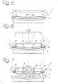
- the lifter 13 is lowered as shown in Figure 5, in such a way as to bring the structure 6 in contact with the clinching die 5.
- the Figures 4 and 5 show that the structure 6 is formed by two pieces of sheet metal 6a and 6b in contact with each other along the respective edges.
- the lower piece 6a is provided with a peripheral edge 16 which is destined to be bent against the edge 17 of the upper piece 6b.
- the hot-curing resin can be spread uniformly along the entire perimeter of the piece 6a before coupling with the piece 6b. Said application can also be performed on the clinching die.
- the presser 7 is lowered.
- the arm 18 of the presser 7 press the edge 17 of the upper piece 6b against the corresponding peripheral edge of the lower piece 6a.
- the presser 7 includes positioning pins for positioning the piece 6b with respect to the piece 6a.
- the industrial robot 11 brings the clinching tool 10 in operative position and moves the tool 10 along the entire perimeter of the structure 6 in such a way as to perform the clinching of the edge 16 of the lower piece 6a against the edge 17 of the upper piece 6b.
- the clinching operation can be performed as described in detail in European Patent application no. 03001105.0 mentioned above.
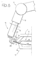
- the industrial robot 11 After performing the clinching operation on the edges 16, 17, the industrial robot 11 performs a tool change operation during which the clinching tool 10 is replaced with an induction heating device 19 ( Figure 8).
- the induction heating device 19 comprises a C-shaped heating coil 20 borne by a body 22.
- the body 22 is fastened to the wrist 12 of the industrial robot 11 and receives electrical power through the robot 11.
- the induction heating device can be of the type supplied by the British Company EFD Induction Ltd.
- the heating coil 20 is positioned at the areas in which the resin is to be polymerised.
- the number and the position of the polymerisation areas are decided according to the dimensions and the shape of the structure 6.
- the robot 11 positions the coil 20 in preprogrammed areas and maintains the coil 20 in position for the time required to obtain the polymerisation of the resin.
- the heating coil 20 is positioned in such a way that its parallel branches 23 are at opposite sides of the clinched edges 16, 17 so that the electrical induction field produced by the device 19 is concentrated exclusively on the clinched edges 16, 17.
- the lifter 13 allows to detach the clinched edges 16, 17 from the clinching die 5, in order to enable the positioning of the heating coil 20 in such a way that the two branches 23 are at opposite sides with respect to the clinched edges 16, 17.
- the presser 7 and the bearing element 14 hold the structure 6 leaving the clinched edges 16, 17 free, in order to prevent any interference with the heating coil 20.
- the coil 20 is moved in succession in all areas where the resin needs to be polymerised, whose position is known by the control unit of the robot 11. At the ends of this step, the robot 11 performs a new tool change operation during which it replaces the induction heating device 19 with the clinching tool 10.
- the lifter 13 remains in the raised position to receive a new structure 6 and the presser 7 is moved upwards in such a way as to free the station for the unloading operation.
- the heating device 19 is constructed in such a way as to be interchangeable with the clinching tool 10.
- the clinching tool 10 and the heating device 19 shall therefore be provided with attachment means able to cooperate with complementary attachment means provided on the wrist 12 of the robot 11.
Landscapes
- Engineering & Computer Science (AREA)
- Mechanical Engineering (AREA)
- Lining Or Joining Of Plastics Or The Like (AREA)
- General Induction Heating (AREA)
- Shaping Of Tube Ends By Bending Or Straightening (AREA)
- Pretreatment Of Seeds And Plants (AREA)
- Paper (AREA)
- Laminated Bodies (AREA)
Claims (9)
- Verfahren zum Crimpen von Metallblechteilen, das die Schritte umfasst:- Positionieren zweier Metallblechteile (6a, 6b) in einer Crimpstation (3), die eine Crimpform (5) einschließt, wobei die zwei Metallblechteile (6a, 6b) mit wenigstens einer Fläche ihres Randes mit einem darauf aufgebrachten Heißhärtungsharz vorgesehen sind,- Durchführen einer Crimpoperation entlang dem Rand (16, 17) der Teile (6a, 6b), und- Polymerisieren des Harzes durch Erwärmen des gecrimpten Randes (16, 17),dadurch gekennzeichnet, dass das Verfahren die folgenden Arbeitsvorgänge umfasst:- Abheben der Metallblechteile (6a, 6b) von der Crimpform (5) am Ende des Crimpvorgangs, und- Ausführen einer Induktionserwärmungsoperation in derselben Crimpstation (3) mittels einer Induktionsheizvorrichtung (19), die eine lokal begrenzte Erwärmung der gecrimpten Ränder (16, 17) durchführt, wenn sich die zwei Metallblechteile in der angehobenen Stellung bezüglich der Crimpform (5) befinden.
- Verfahren nach Anspruch 1, dadurch gekennzeichnet, dass ein Industrieroboter (11) verwendet wird, um ein Crimpwerkzeug entlang dem Umfang der zu crimpenden Teile (6a, 6b) zu bewegen, und dass derselbe Industrieroboter (11) verwendet wird, um die Heizvorrichtung (19) zu bewegen.
- Verfahren nach Anspruch 1, dadurch gekennzeichnet, dass der Industrieroboter (11) zur Durchführung von Werkzeugwechseloperationen programmiert ist, um das Crimpwerkzeug (10) durch das Heizwerkzeug (19) zu ersetzen und umgekehrt.
- Vorrichtung zum Crimpen von Metallblechteilen, umfassend:- eine Crimpstation (3) mit einer Crimpform (5), die imstande ist, eine Struktur (6) mit wenigstens zwei Metallblechteilen (6a, 6b) aufzunehmen, die mittels Crimpen gegenseitig verbunden werden sollen, wobei ein Heißhärtungsharz auf wenigstens einen Abschnitt des Randes (16, 17) der Teile (6a, 6b) aufgebracht wird,- Mittel (10) zur Durchführung einer Crimpoperation an den Umfangsrändern (16, 17) der Teile (6a, 6b),dadurch gekennzeichnet, dass:- die Crimpstation (3) eine Hebevorrichtung (13) zum Abheben der Metallblechteile (6a, 6b) von der Crimpform (5) am Ende des Crimpvorgangs umfasst, und dass- die Vorrichtung eine Induktionsheizvorrichtung (19) zum Durchführen einer lokal begrenzten Erwärmung von Abschnitten der gecrimpten Ränder (16, 17) umfasst, wobei die Heizvorrichtung (19) imstande ist, in vorbestimmten Flächen des Randes der gecrimpten Teile (6a, 6b) positioniert zu werden, wenn die gecrimpten Teile (6a, 6b) von der Crimpform (5) angehoben sind.
- Vorrichtung nach Anspruch 4, dadurch gekennzeichnet, dass sie einen Industrieroboter (11) umfasst, der imstande ist, ein Crimpwerkzeug (10) und die Induktionsheizvorrichtung (19) entlang dem Rand der Struktur (6) zu bewegen.
- Vorrichtung nach Anspruch 5, dadurch gekennzeichnet, dass das Crimpwerkzeug (10) und die Induktionsheizvorrichtung (19) gegenseitig austauschbar sind.
- Vorrichtung nach Anspruch 4, dadurch gekennzeichnet, dass die Crimpstation (3) eine Crimpform (5) mit einer mittigen Öffnung umfasst, in der die zwischen einer angehobenen Stellung und einer abgesenkten Stellung bewegliche Hebevorrichtung (13) untergebracht ist.
- Vorrichtung nach Anspruch 5, dadurch gekennzeichnet, dass die Induktionsheizvorrichtung (19) eine im Wesentlichen C-förmige Heizspule (20) umfasst, die imstande ist, einen lokal begrenzten Abschnitt der gecrimpten Ränder (16, 17) zu umschließen.
- Vorrichtung nach Anspruch 5, dadurch gekennzeichnet, dass die Induktionsheizvorrichtung (19) mit Befestigungsmitteln versehen ist, die mit komplementären Befestigungsmitteln zusammenwirken, die durch ein Handgelenk (12) des Industrieroboters (11) gestützt sind.
Applications Claiming Priority (2)
| Application Number | Priority Date | Filing Date | Title |
|---|---|---|---|
| ITTO20030726 | 2003-09-23 | ||
| IT000726A ITTO20030726A1 (it) | 2003-09-23 | 2003-09-23 | Procedimento ed impianto per la graffatura di pezzi di lamiera |
Publications (2)
| Publication Number | Publication Date |
|---|---|
| EP1518617A1 EP1518617A1 (de) | 2005-03-30 |
| EP1518617B1 true EP1518617B1 (de) | 2006-06-14 |
Family
ID=34179358
Family Applications (1)
| Application Number | Title | Priority Date | Filing Date |
|---|---|---|---|
| EP04020970A Expired - Lifetime EP1518617B1 (de) | 2003-09-23 | 2004-09-03 | Verfahren und Vorrichtung zum Crimpen von Metallblechen |
Country Status (9)
| Country | Link |
|---|---|
| US (1) | US7455746B2 (de) |
| EP (1) | EP1518617B1 (de) |
| JP (1) | JP2005103642A (de) |
| CN (1) | CN1601120A (de) |
| AT (1) | ATE329705T1 (de) |
| BR (1) | BRPI0404079A (de) |
| DE (1) | DE602004001190T2 (de) |
| ES (1) | ES2266967T3 (de) |
| IT (1) | ITTO20030726A1 (de) |
Families Citing this family (18)
| Publication number | Priority date | Publication date | Assignee | Title |
|---|---|---|---|---|
| US7100271B2 (en) * | 2003-09-23 | 2006-09-05 | Valiant Corporation | Automotive vehicle framing system |
| KR100645586B1 (ko) * | 2005-04-14 | 2006-11-14 | 현대자동차주식회사 | 차체 패널 헤밍 시스템 |
| EP2116318B1 (de) | 2005-12-05 | 2011-04-27 | Honda Motor Co., Ltd. | Umbördelvorrichtung |
| AU2006345829B2 (en) * | 2006-07-05 | 2011-07-07 | Hiroyasu Kawamata | A method for joining a metal plate |
| CN100418657C (zh) * | 2006-08-02 | 2008-09-17 | 杭州汇同链传动有限公司 | 链板片加工工艺 |
| DE202007010595U1 (de) * | 2007-07-27 | 2008-12-04 | Kuka Systems Gmbh | Falzeinrichtung |
| DE102007054559A1 (de) * | 2007-11-15 | 2009-05-20 | Thyssenkrupp Drauz Nothelfer Gmbh | Vorrichtung zum Verbinden von Blechen sowie schwenkbares Aufnahmeelement |
| IT1392740B1 (it) * | 2008-12-23 | 2012-03-16 | Comau Spa | Metodo ed apparecchiatura per la graffatura di elementi di lamiera metallica e la successiva applicazione di punti di saldatura elettrica agli elementi graffati |
| DE102009040915A1 (de) * | 2009-09-10 | 2011-04-07 | Continental Automotive Gmbh | Verfahren zum Verbinden von Gehäuseteilen |
| WO2011135619A1 (ja) * | 2010-04-27 | 2011-11-03 | 株式会社ヒロテック | 加工装置 |
| WO2011135620A1 (ja) * | 2010-04-27 | 2011-11-03 | 株式会社ヒロテック | 加工装置 |
| US9259774B2 (en) | 2011-05-03 | 2016-02-16 | GM Global Technology Operations LLC | Clinching method and tool for performing the same |
| US8640321B2 (en) | 2011-05-03 | 2014-02-04 | GM Global Technology Operations LLC | Clinching method and tool for performing the same |
| DE102011085590A1 (de) * | 2011-11-02 | 2013-05-02 | Ford Global Technologies, Llc | Karosserieträger einer Fahrzeugkarosserie, insbesondere B-Säule |
| CN103846329B (zh) | 2012-11-30 | 2017-03-01 | 通用汽车环球科技运作有限责任公司 | 滚子卷边 |
| CN103878249B (zh) * | 2014-02-26 | 2015-09-16 | 安徽省安运机械制造有限公司 | 一种卷筒增厚用扎紧机 |
| DE102021132428A1 (de) * | 2021-12-09 | 2023-06-15 | Bayerische Motoren Werke Aktiengesellschaft | Falzformwerkzeug, Falzformeinrichtung und Verfahren zur Herstellung einer Falzklebeverbindung |
| CN117067614A (zh) * | 2023-08-16 | 2023-11-17 | 十堰一诺智能装备有限公司 | 一种感应加热夹具及方法 |
Family Cites Families (13)
| Publication number | Priority date | Publication date | Assignee | Title |
|---|---|---|---|---|
| JPS5326216B2 (de) * | 1973-08-22 | 1978-08-01 | ||
| IT1179967B (it) * | 1984-02-13 | 1987-09-23 | Bisiach & Carru | Meccanismo per il cambio automatico di utensili su robot industriali |
| JPH03101312U (de) * | 1990-01-31 | 1991-10-22 | ||
| EP0577876B1 (de) * | 1992-07-09 | 1996-09-04 | TRIENGINEERING Co., Ltd. | Vorrichtung zum Verbinden eines Werkstücks |
| JPH07185675A (ja) * | 1993-12-28 | 1995-07-25 | Honda Motor Co Ltd | ヘミング加工装置 |
| US5587042A (en) * | 1994-09-19 | 1996-12-24 | E. R. St. Denis & Sons Ltd. | Adhesive curing system and method for a hemming machine |
| US5948185A (en) | 1997-05-01 | 1999-09-07 | General Motors Corporation | Method for improving the hemmability of age-hardenable aluminum sheet |
| JP3596585B2 (ja) * | 1997-12-25 | 2004-12-02 | 三菱自動車工業株式会社 | 板金ワークのプリキュア装置 |
| DE19927207A1 (de) * | 1999-06-15 | 2000-12-28 | Thyssenkrupp Ind Ag | Verfahren zum randseitigen Verbinden von Blechen |
| JP2000354989A (ja) * | 1999-06-16 | 2000-12-26 | Fanuc Ltd | 自動刃具交換装置 |
| JP3688534B2 (ja) * | 1999-11-17 | 2005-08-31 | ダイハツ工業株式会社 | ロボット装置を用いた加工装置 |
| JP3582450B2 (ja) * | 2000-04-05 | 2004-10-27 | 日産自動車株式会社 | へミング装置およびへミング方法 |
| JP4027708B2 (ja) * | 2002-04-26 | 2007-12-26 | 株式会社伸興メカニック | ヘミング加工装置 |
-
2003
- 2003-09-23 IT IT000726A patent/ITTO20030726A1/it unknown
-
2004
- 2004-09-03 DE DE602004001190T patent/DE602004001190T2/de not_active Expired - Lifetime
- 2004-09-03 AT AT04020970T patent/ATE329705T1/de not_active IP Right Cessation
- 2004-09-03 ES ES04020970T patent/ES2266967T3/es not_active Expired - Lifetime
- 2004-09-03 EP EP04020970A patent/EP1518617B1/de not_active Expired - Lifetime
- 2004-09-13 US US10/939,724 patent/US7455746B2/en not_active Expired - Fee Related
- 2004-09-22 BR BR0404079-1A patent/BRPI0404079A/pt not_active IP Right Cessation
- 2004-09-23 CN CN200410079845.0A patent/CN1601120A/zh active Pending
- 2004-09-24 JP JP2004277138A patent/JP2005103642A/ja active Pending
Also Published As
| Publication number | Publication date |
|---|---|
| ITTO20030726A1 (it) | 2005-03-24 |
| CN1601120A (zh) | 2005-03-30 |
| US7455746B2 (en) | 2008-11-25 |
| US20050060866A1 (en) | 2005-03-24 |
| ATE329705T1 (de) | 2006-07-15 |
| JP2005103642A (ja) | 2005-04-21 |
| DE602004001190T2 (de) | 2007-03-08 |
| EP1518617A1 (de) | 2005-03-30 |
| DE602004001190D1 (de) | 2006-07-27 |
| BRPI0404079A (pt) | 2005-05-24 |
| ES2266967T3 (es) | 2007-03-01 |
Similar Documents
| Publication | Publication Date | Title |
|---|---|---|
| EP1518617A1 (de) | Verfahren und Vorrichtung zum Crimpen von Metallblechen | |
| US20080184760A1 (en) | Method and apparatus for hemming panels together | |
| KR101575275B1 (ko) | 핫 스탬핑용 열처리 장치 및 이를 이용한 성형방법 | |
| CA2157699A1 (en) | Adhesive Curing System and Method for a Hemming Machine | |
| US6446478B1 (en) | Two-stage hemming machine with movable dies | |
| US7263757B2 (en) | Electromagnetic trimming, flanging and hemming apparatus and method | |
| EP1447155B1 (de) | Rollbördelwerkzeug und Bördelverfahren | |
| US20110296892A1 (en) | Method and apparatus for forming flanges during hot-forming | |
| EP1785340B1 (de) | Vorrichtung zum Fixieren von Elementen von einem Kraftfahrzeugaufbau, und ein Verfahren dazu | |
| US7210323B2 (en) | Binder apparatus for sheet forming | |
| WO2002042019A2 (en) | Edge bending method and apparatus | |
| US7997113B2 (en) | System and method for hemming components | |
| CN100484658C (zh) | 卷边机的弯边系统 | |
| KR20060010978A (ko) | 헤밍 프레스 장치 | |
| EP1925379B1 (de) | Falz- und Befestigungsvorrichtung zur Montage von Elementen auf eine Verbundplatte, insbesondere für Kraftfahrzeugkarosserie | |
| CN116493463A (zh) | 一种钣金柜体外壳成型用自动化折边装置及使用方法 | |
| KR100559331B1 (ko) | 헤밍 프레스 장치 | |
| KR101329052B1 (ko) | 차량 도어의 윈도우용 개구부를 위한 헤밍장치 | |
| KR100422655B1 (ko) | 헤밍 프레스 장치 | |
| KR100966244B1 (ko) | 롤 헤드를 이용한 썬루프 헤밍 장치 | |
| CA2634705C (en) | Apparatus for machining flange of wheel arch | |
| KR100427351B1 (ko) | 플렉시블 다이 캐리어를 장착한 정밀 클린칭 타입 헤밍 머신 | |
| CN223280146U (zh) | 一种半壳钢板展开料搬运装置及半壳生产线 | |
| US12097548B2 (en) | Apparatus and methods for forming an attachment pad in high strength steel materials | |
| KR102387147B1 (ko) | 헤밍 시스템 |
Legal Events
| Date | Code | Title | Description |
|---|---|---|---|
| PUAI | Public reference made under article 153(3) epc to a published international application that has entered the european phase |
Free format text: ORIGINAL CODE: 0009012 |
|
| AK | Designated contracting states |
Kind code of ref document: A1 Designated state(s): AT BE BG CH CY CZ DE DK EE ES FI FR GB GR HU IE IT LI LU MC NL PL PT RO SE SI SK TR |
|
| AX | Request for extension of the european patent |
Extension state: AL HR LT LV MK |
|
| 17P | Request for examination filed |
Effective date: 20050627 |
|
| GRAP | Despatch of communication of intention to grant a patent |
Free format text: ORIGINAL CODE: EPIDOSNIGR1 |
|
| AKX | Designation fees paid |
Designated state(s): AT BE BG CH CY CZ DE DK EE ES FI FR GB GR HU IE IT LI LU MC NL PL PT RO SE SI SK TR |
|
| GRAS | Grant fee paid |
Free format text: ORIGINAL CODE: EPIDOSNIGR3 |
|
| GRAA | (expected) grant |
Free format text: ORIGINAL CODE: 0009210 |
|
| AK | Designated contracting states |
Kind code of ref document: B1 Designated state(s): AT BE BG CH CY CZ DE DK EE ES FI FR GB GR HU IE IT LI LU MC NL PL PT RO SE SI SK TR |
|
| PG25 | Lapsed in a contracting state [announced via postgrant information from national office to epo] |
Ref country code: PL Free format text: LAPSE BECAUSE OF FAILURE TO SUBMIT A TRANSLATION OF THE DESCRIPTION OR TO PAY THE FEE WITHIN THE PRESCRIBED TIME-LIMIT Effective date: 20060614 Ref country code: RO Free format text: LAPSE BECAUSE OF FAILURE TO SUBMIT A TRANSLATION OF THE DESCRIPTION OR TO PAY THE FEE WITHIN THE PRESCRIBED TIME-LIMIT Effective date: 20060614 Ref country code: CZ Free format text: LAPSE BECAUSE OF FAILURE TO SUBMIT A TRANSLATION OF THE DESCRIPTION OR TO PAY THE FEE WITHIN THE PRESCRIBED TIME-LIMIT Effective date: 20060614 Ref country code: FI Free format text: LAPSE BECAUSE OF FAILURE TO SUBMIT A TRANSLATION OF THE DESCRIPTION OR TO PAY THE FEE WITHIN THE PRESCRIBED TIME-LIMIT Effective date: 20060614 Ref country code: LI Free format text: LAPSE BECAUSE OF FAILURE TO SUBMIT A TRANSLATION OF THE DESCRIPTION OR TO PAY THE FEE WITHIN THE PRESCRIBED TIME-LIMIT Effective date: 20060614 Ref country code: CH Free format text: LAPSE BECAUSE OF FAILURE TO SUBMIT A TRANSLATION OF THE DESCRIPTION OR TO PAY THE FEE WITHIN THE PRESCRIBED TIME-LIMIT Effective date: 20060614 Ref country code: SK Free format text: LAPSE BECAUSE OF FAILURE TO SUBMIT A TRANSLATION OF THE DESCRIPTION OR TO PAY THE FEE WITHIN THE PRESCRIBED TIME-LIMIT Effective date: 20060614 Ref country code: NL Free format text: LAPSE BECAUSE OF FAILURE TO SUBMIT A TRANSLATION OF THE DESCRIPTION OR TO PAY THE FEE WITHIN THE PRESCRIBED TIME-LIMIT Effective date: 20060614 Ref country code: SI Free format text: LAPSE BECAUSE OF FAILURE TO SUBMIT A TRANSLATION OF THE DESCRIPTION OR TO PAY THE FEE WITHIN THE PRESCRIBED TIME-LIMIT Effective date: 20060614 |
|
| REG | Reference to a national code |
Ref country code: GB Ref legal event code: FG4D |
|
| REG | Reference to a national code |
Ref country code: CH Ref legal event code: EP |
|
| REG | Reference to a national code |
Ref country code: IE Ref legal event code: FG4D |
|
| REF | Corresponds to: |
Ref document number: 602004001190 Country of ref document: DE Date of ref document: 20060727 Kind code of ref document: P |
|
| PG25 | Lapsed in a contracting state [announced via postgrant information from national office to epo] |
Ref country code: IE Free format text: LAPSE BECAUSE OF NON-PAYMENT OF DUE FEES Effective date: 20060904 |
|
| PG25 | Lapsed in a contracting state [announced via postgrant information from national office to epo] |
Ref country code: SE Free format text: LAPSE BECAUSE OF FAILURE TO SUBMIT A TRANSLATION OF THE DESCRIPTION OR TO PAY THE FEE WITHIN THE PRESCRIBED TIME-LIMIT Effective date: 20060914 Ref country code: DK Free format text: LAPSE BECAUSE OF FAILURE TO SUBMIT A TRANSLATION OF THE DESCRIPTION OR TO PAY THE FEE WITHIN THE PRESCRIBED TIME-LIMIT Effective date: 20060914 |
|
| PG25 | Lapsed in a contracting state [announced via postgrant information from national office to epo] |
Ref country code: MC Free format text: LAPSE BECAUSE OF NON-PAYMENT OF DUE FEES Effective date: 20060930 |
|
| PG25 | Lapsed in a contracting state [announced via postgrant information from national office to epo] |
Ref country code: PT Free format text: LAPSE BECAUSE OF FAILURE TO SUBMIT A TRANSLATION OF THE DESCRIPTION OR TO PAY THE FEE WITHIN THE PRESCRIBED TIME-LIMIT Effective date: 20061114 |
|
| NLV1 | Nl: lapsed or annulled due to failure to fulfill the requirements of art. 29p and 29m of the patents act | ||
| REG | Reference to a national code |
Ref country code: CH Ref legal event code: PL |
|
| ET | Fr: translation filed | ||
| REG | Reference to a national code |
Ref country code: ES Ref legal event code: FG2A Ref document number: 2266967 Country of ref document: ES Kind code of ref document: T3 |
|
| PLBE | No opposition filed within time limit |
Free format text: ORIGINAL CODE: 0009261 |
|
| STAA | Information on the status of an ep patent application or granted ep patent |
Free format text: STATUS: NO OPPOSITION FILED WITHIN TIME LIMIT |
|
| 26N | No opposition filed |
Effective date: 20070315 |
|
| PG25 | Lapsed in a contracting state [announced via postgrant information from national office to epo] |
Ref country code: GR Free format text: LAPSE BECAUSE OF FAILURE TO SUBMIT A TRANSLATION OF THE DESCRIPTION OR TO PAY THE FEE WITHIN THE PRESCRIBED TIME-LIMIT Effective date: 20060915 |
|
| PG25 | Lapsed in a contracting state [announced via postgrant information from national office to epo] |
Ref country code: BG Free format text: LAPSE BECAUSE OF FAILURE TO SUBMIT A TRANSLATION OF THE DESCRIPTION OR TO PAY THE FEE WITHIN THE PRESCRIBED TIME-LIMIT Effective date: 20060914 Ref country code: EE Free format text: LAPSE BECAUSE OF FAILURE TO SUBMIT A TRANSLATION OF THE DESCRIPTION OR TO PAY THE FEE WITHIN THE PRESCRIBED TIME-LIMIT Effective date: 20060614 |
|
| PG25 | Lapsed in a contracting state [announced via postgrant information from national office to epo] |
Ref country code: LU Free format text: LAPSE BECAUSE OF NON-PAYMENT OF DUE FEES Effective date: 20060903 Ref country code: TR Free format text: LAPSE BECAUSE OF FAILURE TO SUBMIT A TRANSLATION OF THE DESCRIPTION OR TO PAY THE FEE WITHIN THE PRESCRIBED TIME-LIMIT Effective date: 20060614 Ref country code: HU Free format text: LAPSE BECAUSE OF FAILURE TO SUBMIT A TRANSLATION OF THE DESCRIPTION OR TO PAY THE FEE WITHIN THE PRESCRIBED TIME-LIMIT Effective date: 20061215 |
|
| PG25 | Lapsed in a contracting state [announced via postgrant information from national office to epo] |
Ref country code: CY Free format text: LAPSE BECAUSE OF FAILURE TO SUBMIT A TRANSLATION OF THE DESCRIPTION OR TO PAY THE FEE WITHIN THE PRESCRIBED TIME-LIMIT Effective date: 20060614 |
|
| PGFP | Annual fee paid to national office [announced via postgrant information from national office to epo] |
Ref country code: AT Payment date: 20080912 Year of fee payment: 5 Ref country code: FR Payment date: 20080915 Year of fee payment: 5 |
|
| PGFP | Annual fee paid to national office [announced via postgrant information from national office to epo] |
Ref country code: BE Payment date: 20080922 Year of fee payment: 5 Ref country code: ES Payment date: 20081021 Year of fee payment: 5 |
|
| BERE | Be: lapsed |
Owner name: *COMAU S.P.A. Effective date: 20090930 |
|
| REG | Reference to a national code |
Ref country code: FR Ref legal event code: ST Effective date: 20100531 |
|
| PG25 | Lapsed in a contracting state [announced via postgrant information from national office to epo] |
Ref country code: AT Free format text: LAPSE BECAUSE OF NON-PAYMENT OF DUE FEES Effective date: 20090903 |
|
| PG25 | Lapsed in a contracting state [announced via postgrant information from national office to epo] |
Ref country code: FR Free format text: LAPSE BECAUSE OF NON-PAYMENT OF DUE FEES Effective date: 20090930 |
|
| PG25 | Lapsed in a contracting state [announced via postgrant information from national office to epo] |
Ref country code: BE Free format text: LAPSE BECAUSE OF NON-PAYMENT OF DUE FEES Effective date: 20090930 |
|
| REG | Reference to a national code |
Ref country code: ES Ref legal event code: FD2A Effective date: 20110711 |
|
| PG25 | Lapsed in a contracting state [announced via postgrant information from national office to epo] |
Ref country code: ES Free format text: LAPSE BECAUSE OF NON-PAYMENT OF DUE FEES Effective date: 20110629 |
|
| PG25 | Lapsed in a contracting state [announced via postgrant information from national office to epo] |
Ref country code: ES Free format text: LAPSE BECAUSE OF NON-PAYMENT OF DUE FEES Effective date: 20090904 |
|
| PGFP | Annual fee paid to national office [announced via postgrant information from national office to epo] |
Ref country code: DE Payment date: 20110831 Year of fee payment: 8 |
|
| REG | Reference to a national code |
Ref country code: DE Ref legal event code: R231 Ref document number: 602004001190 Country of ref document: DE |
|
| PG25 | Lapsed in a contracting state [announced via postgrant information from national office to epo] |
Ref country code: DE Free format text: LAPSE BECAUSE OF THE APPLICANT RENOUNCES Effective date: 20120730 |
|
| PGFP | Annual fee paid to national office [announced via postgrant information from national office to epo] |
Ref country code: IT Payment date: 20120903 Year of fee payment: 9 |
|
| PG25 | Lapsed in a contracting state [announced via postgrant information from national office to epo] |
Ref country code: IT Free format text: LAPSE BECAUSE OF NON-PAYMENT OF DUE FEES Effective date: 20130903 |
|
| PGFP | Annual fee paid to national office [announced via postgrant information from national office to epo] |
Ref country code: GB Payment date: 20150902 Year of fee payment: 12 |
|
| GBPC | Gb: european patent ceased through non-payment of renewal fee |
Effective date: 20160903 |
|
| PG25 | Lapsed in a contracting state [announced via postgrant information from national office to epo] |
Ref country code: GB Free format text: LAPSE BECAUSE OF NON-PAYMENT OF DUE FEES Effective date: 20160903 |