EP1518532A2 - Massageaufsatz für ein Fusspflegegerät sowie Fusspflegegerät - Google Patents
Massageaufsatz für ein Fusspflegegerät sowie Fusspflegegerät Download PDFInfo
- Publication number
- EP1518532A2 EP1518532A2 EP04104529A EP04104529A EP1518532A2 EP 1518532 A2 EP1518532 A2 EP 1518532A2 EP 04104529 A EP04104529 A EP 04104529A EP 04104529 A EP04104529 A EP 04104529A EP 1518532 A2 EP1518532 A2 EP 1518532A2
- Authority
- EP
- European Patent Office
- Prior art keywords
- massage
- movement
- care device
- foot
- roller assembly
- Prior art date
- Legal status (The legal status is an assumption and is not a legal conclusion. Google has not performed a legal analysis and makes no representation as to the accuracy of the status listed.)
- Granted
Links
- 230000008878 coupling Effects 0.000 claims abstract description 21
- 238000010168 coupling process Methods 0.000 claims abstract description 21
- 238000005859 coupling reaction Methods 0.000 claims abstract description 21
- 239000011324 bead Substances 0.000 claims description 4
- 239000007788 liquid Substances 0.000 claims description 2
- 241000047428 Halter Species 0.000 description 2
- 230000005484 gravity Effects 0.000 description 2
- 206010020649 Hyperkeratosis Diseases 0.000 description 1
- 208000012886 Vertigo Diseases 0.000 description 1
- 238000006243 chemical reaction Methods 0.000 description 1
- 230000000694 effects Effects 0.000 description 1
- 230000000474 nursing effect Effects 0.000 description 1
- 239000008262 pumice Substances 0.000 description 1
- 230000000630 rising effect Effects 0.000 description 1
Images
Classifications
-
- A—HUMAN NECESSITIES
- A61—MEDICAL OR VETERINARY SCIENCE; HYGIENE
- A61H—PHYSICAL THERAPY APPARATUS, e.g. DEVICES FOR LOCATING OR STIMULATING REFLEX POINTS IN THE BODY; ARTIFICIAL RESPIRATION; MASSAGE; BATHING DEVICES FOR SPECIAL THERAPEUTIC OR HYGIENIC PURPOSES OR SPECIFIC PARTS OF THE BODY
- A61H23/00—Percussion or vibration massage, e.g. using supersonic vibration; Suction-vibration massage; Massage with moving diaphragms
- A61H23/02—Percussion or vibration massage, e.g. using supersonic vibration; Suction-vibration massage; Massage with moving diaphragms with electric or magnetic drive
- A61H23/0254—Percussion or vibration massage, e.g. using supersonic vibration; Suction-vibration massage; Massage with moving diaphragms with electric or magnetic drive with rotary motor
-
- A—HUMAN NECESSITIES
- A61—MEDICAL OR VETERINARY SCIENCE; HYGIENE
- A61H—PHYSICAL THERAPY APPARATUS, e.g. DEVICES FOR LOCATING OR STIMULATING REFLEX POINTS IN THE BODY; ARTIFICIAL RESPIRATION; MASSAGE; BATHING DEVICES FOR SPECIAL THERAPEUTIC OR HYGIENIC PURPOSES OR SPECIFIC PARTS OF THE BODY
- A61H15/00—Massage by means of rollers, balls, e.g. inflatable, chains, or roller chains
- A61H15/0078—Massage by means of rollers, balls, e.g. inflatable, chains, or roller chains power-driven
-
- A—HUMAN NECESSITIES
- A61—MEDICAL OR VETERINARY SCIENCE; HYGIENE
- A61H—PHYSICAL THERAPY APPARATUS, e.g. DEVICES FOR LOCATING OR STIMULATING REFLEX POINTS IN THE BODY; ARTIFICIAL RESPIRATION; MASSAGE; BATHING DEVICES FOR SPECIAL THERAPEUTIC OR HYGIENIC PURPOSES OR SPECIFIC PARTS OF THE BODY
- A61H35/00—Baths for specific parts of the body
- A61H35/006—Baths for specific parts of the body for the feet
-
- A—HUMAN NECESSITIES
- A61—MEDICAL OR VETERINARY SCIENCE; HYGIENE
- A61H—PHYSICAL THERAPY APPARATUS, e.g. DEVICES FOR LOCATING OR STIMULATING REFLEX POINTS IN THE BODY; ARTIFICIAL RESPIRATION; MASSAGE; BATHING DEVICES FOR SPECIAL THERAPEUTIC OR HYGIENIC PURPOSES OR SPECIFIC PARTS OF THE BODY
- A61H2201/00—Characteristics of apparatus not provided for in the preceding codes
- A61H2201/14—Special force transmission means, i.e. between the driving means and the interface with the user
- A61H2201/1418—Cam
-
- A—HUMAN NECESSITIES
- A61—MEDICAL OR VETERINARY SCIENCE; HYGIENE
- A61H—PHYSICAL THERAPY APPARATUS, e.g. DEVICES FOR LOCATING OR STIMULATING REFLEX POINTS IN THE BODY; ARTIFICIAL RESPIRATION; MASSAGE; BATHING DEVICES FOR SPECIAL THERAPEUTIC OR HYGIENIC PURPOSES OR SPECIFIC PARTS OF THE BODY
- A61H2201/00—Characteristics of apparatus not provided for in the preceding codes
- A61H2201/16—Physical interface with patient
- A61H2201/1602—Physical interface with patient kind of interface, e.g. head rest, knee support or lumbar support
- A61H2201/164—Feet or leg, e.g. pedal
-
- A—HUMAN NECESSITIES
- A61—MEDICAL OR VETERINARY SCIENCE; HYGIENE
- A61H—PHYSICAL THERAPY APPARATUS, e.g. DEVICES FOR LOCATING OR STIMULATING REFLEX POINTS IN THE BODY; ARTIFICIAL RESPIRATION; MASSAGE; BATHING DEVICES FOR SPECIAL THERAPEUTIC OR HYGIENIC PURPOSES OR SPECIFIC PARTS OF THE BODY
- A61H2201/00—Characteristics of apparatus not provided for in the preceding codes
- A61H2201/16—Physical interface with patient
- A61H2201/1657—Movement of interface, i.e. force application means
- A61H2201/1664—Movement of interface, i.e. force application means linear
- A61H2201/1669—Movement of interface, i.e. force application means linear moving along the body in a reciprocating manner
-
- A—HUMAN NECESSITIES
- A61—MEDICAL OR VETERINARY SCIENCE; HYGIENE
- A61H—PHYSICAL THERAPY APPARATUS, e.g. DEVICES FOR LOCATING OR STIMULATING REFLEX POINTS IN THE BODY; ARTIFICIAL RESPIRATION; MASSAGE; BATHING DEVICES FOR SPECIAL THERAPEUTIC OR HYGIENIC PURPOSES OR SPECIFIC PARTS OF THE BODY
- A61H2205/00—Devices for specific parts of the body
- A61H2205/12—Feet
Definitions
- the invention relates to a massage attachment for a foot care device with a motor driven rotating drive shaft, which massage attachment a coupling portion for torque-locking connection of the massage attachment with the drive shaft of the foot care device and an arrangement for converting over the coupling piece received rotating motion in a to the rotating drive movement distinctive movement of a stroke movement exercising and driven by the arrangement massage element having. Furthermore, the invention relates to a foot care device with a motor, in particular electromotive drive, with a through the Drive rotatably driven drive shaft and with a detachable torque-locking attachable to the free end of the drive shaft Massage attachment.
- a foot care device with a rotatably driven by a motor Drive shaft attachable care or treatment essay, for example a massage attachment is known from DE 295 02 702 U1.
- This Foot care device is part of a foot care device with a foot tub, which is divided with a central bridge in two sections. Each subarea The foot pan serves to receive a foot, so that this on a lying on the trough bottom insert a soles massage can experience.
- the foot well subdividing bridge forms the bottom a cavity in which an electric motor and more for operation foot care device required electrical / electronic elements are included.
- the electric motor drives a drive shaft rotationally on, which is guided up through the top of the web and carries at its upper end a cross piece as a coupling piece.
- This crosspiece serves as a nursing or treatment attachment rotatably mounted on the coupling piece of the drive shaft.
- the care or treatment attachment according to the rotational movement of the drive shaft also set in rotation.
- essays for example, those are used in which several roles are movably mounted, so that at an operation of such an essay by the rotational movement of the essay and the movable storage of roles in the essay targeted Massage be exercised on individual areas of the soles of the feet can.
- an essay can also pumice, about for the removal of calluses, brushes or the like, depending on which care or treatment purposes the essay should serve.
- such a foot care device is also equipped with a vibration generating device to the deposits in the tub sections for massage of the soles of the feet in vibration offset.
- the electric motor as part of the foot care device to power the essay is expediently independent of the Vibration generating device controlled and allowed in contrast to such tone conveniently concerned in which essays on a vibration generator Covering swinging dome be plugged, one much more targeted care or treatment of individual foot areas, in particular also regarding the treatment intensity.
- the previously known Care or treatment essays thus work with their different Embodiments rotatory on the respective desired foot area one.
- a massage attachment of the aforementioned, generic type such educate that with this particular a larger area of the sole of the foot can be massaged pulsatingly, without basically a more powerful drive than to operate needed by other massage attachments.
- the massage attachment has a single massage element that is opposite to a rotary motion the drive shaft is fixed and in which the arrangement for converting the rotary movement of the drive shaft into a drive movement for the massage element a multiple roles comprehensive Roller assembly having roles on a control cam supported by a wave-shaped cam surface, through the rotating drive movement the control cam and the roller assembly be moved relative to each other, so that due to the Supporting arrangement between the rollers of the roller assembly and the Control cam the massage element for exerting an oscillating Hubzi is driven.
- This massage attachment is a particularly effective way Power conversion of the rotary drive movement, provided through the drive shaft of the foot care device, in a lifting movement of Massage element.
- the roles of a roller assembly are based on a control cam, wherein both elements are rotated relative to each other become.
- the movable massage element the control curve and the coupling piece of the massage attachment associated with the roller assembly.
- the rotates Roller arrangement while at the bottom of the massage element arranged control cam is supported on the top of the rollers.
- the Control cam has a wave-shaped in the direction of rotation of the rollers Contour on, so that as a result of the described support arrangement in dependence from the wave contour of the cam, the massage element is lifted by the rollers.
- the return movement after a successful stroke is basically due to gravity and / or by one of User over his foot on the massage tower acting force.
- the movable Massage element have reset elements, such as a Mainspring.
- the massage element loose or at least detachable relative to the roller assembly and to arrange the coupling piece of the massage attachment.
- the massage element in the manner of a cap be formed, in which the roller assembly is received, wherein the Bottom the cap carries the cam and the top the massage surface forms.
- the movable massage element is opposite to the rotating drive movement set, for example, characterized in that the massage element over two or more tongue-like, pointing to best conveniently Sach Has projections, each in an opening of the foot care device, for example inserted into the housing of the foot care device, intervene. Basically, such a massage element does not need to be further secured to become.
- a certain trigger safety is However, provided in a development, at the free ends of this Fort among locking ridges to arrange, which engage behind the opening, so that the massage element only aware, and indeed when creating a certain Withdrawal force can be deducted.
- the foot care device for driving the above-described massage attachment is part of a foot care device according to a preferred embodiment, which has a foot bath.
- the foot care device is in this Integrated foot care device, expediently the free end the drive shaft from the housing of the foot care device to a emerges at such point, which is above the maximum liquid level the foot bath is located.
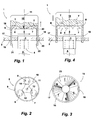
- a massage attachment 1 is on the housing 2 of an otherwise not closer attached pleasant conveniently worn pleasant tongs set.
- the massage attachment 1 has via a coupling section 3, which in the illustrated embodiment via a lower receptacle 4 for torque-locking recording the free end of the possiblyzier réelle associated drive shaft A has.
- the drive shaft A itself is rotating by a Electric motor driven, so that in this way also the coupling portion 3 at a rotational movement of the drive shaft A rotating is driven.
- the coupling section 3 of the massage attachment 1 carries a cylindrical holder 5, in which one of three rollers 6, 7, 8 existing Roll arrangement is added.
- the recorded in the holder 5 Roller assembly is shown in a plan view in Figure 2.
- the Holder 5 has an outer cylindrical rim 9, which is a receptacle 10 defined, in which the roller assembly with the rollers 6, 7, 8 added is.
- the individual rollers 6, 7, 8 are each radially to the Rotary axis 11 extending thru axles 12, 13, 14 rotatably mounted.
- the coupling portion 3 with the holder 5 torque-connected, for example, this molded, so that with a rotating drive the entire holder with the roller assembly is rotated about the axis of rotation 11.
- the massage attachment 1 also has a movable massage element 15, whose movement is different from the rotating drive movement different.
- the massage element 15 is formed as a cap and has a circumferential collar 16 (see Figures 3 and 4), on pointing down to the housing 2 of the foot care device two tongue-like projections 17, 18 are formed. These extensions 17, 18 engage in each case an opening 19, 20 of the housing 2 of the foot care device. In these openings 19, 20, the extensions 17, 18 are opposite a rotating drive movement of the coupling piece 3 and des Halters 5 set.
- the extensions 17, 18 carry at its lower end each a locking bead 21, 22 which engages behind the housing wall.
- the Clear width of the openings 19, 20 is designed so that the Rastwülste 21st or 22 can pass through the openings.
- the ridges 21, 22 serve to hold the massage element 15 on the housing 2. Nevertheless, the massage element 15 can easily be removed by peeling be removed from the housing 2.
- the massage element 15 carries on the underside a control cam 23, the one Has wave-shaped contour, in Figure 3, the wave crests with a B and the troughs are marked with a T.
- the wave crests with a B and the troughs are marked with a T.
- the illustrated Embodiment is seen in the circumferential direction wavy Contour of the cam 23 designed so that three peaks B and three troughs T are formed.
- Position between the holder 5 with its roller assembly and the massage element 15 are the wave crests B between the single rollers 6, 7, 8. In this position, the bottom of the Massage element 15 with its troughs T on the rollers 6, 7, 8 from.
- FIG. 4 shows this Massage element 15 in its raised position, in which the Wave crests B of the control cam 23 on the rollers 6, 7, 8 are supported.
- a Return movement of the massage element 15 upon further rotation of the Halters 5 takes place in the illustrated embodiment, first Due to gravity, when using the massage attachment 1 by the counterforce of a foot to be massaged.
- the massage attachment 15 can be used together with the holder 5 of the foot care device be removed. Furthermore, the massage element 15 be solved by the holder 5, in the event that the massage element 15 by another, for example, with a different cam characteristic to be replaced or even without such a massage element can be used.
- the outside of the holder 5 and the inner surface of the collar 16 of the Massage element 15 are coordinated, so that the massage element 15 in terms of its oscillating stroke on the Holder 5 is guided.
Landscapes
- Health & Medical Sciences (AREA)
- Epidemiology (AREA)
- Pain & Pain Management (AREA)
- Physical Education & Sports Medicine (AREA)
- Rehabilitation Therapy (AREA)
- Life Sciences & Earth Sciences (AREA)
- Animal Behavior & Ethology (AREA)
- General Health & Medical Sciences (AREA)
- Public Health (AREA)
- Veterinary Medicine (AREA)
- Massaging Devices (AREA)
Abstract
Description
- Fig. 1:
- eine schematisierte, zum Teil quer geschnittene Darstellung eines auf ein Fußpflegegerät aufgesetzten Massageaufsatz,
- Fig. 2:
- eine Draufsicht auf den unteren Teil des Massageaufsatzes der Figur 1,
- Fig. 3:
- eine Unteransicht des beweglichen Massageelementes des Massageaufsatzes der Figur 1 mit einer unterseitigen Steuerkurve und
- Fig. 4:
- eine Darstellung entsprechend Figur 1 nach Drehen des unteren Elementes des Massageaufsatzes gegenüber dem oberen.
- 1
- Massageaufsatz
- 2
- Gehäuse
- 3
- Kupplungsabschnitt
- 4
- Aufnahme
- 5
- Halter
- 6
- Rolle
- 7
- Rolle
- 8
- Rolle
- 9
- Rand
- 10
- Aufnahme
- 11
- Drehachse
- 12
- Steckachse
- 13
- Steckachse
- 14
- Steckachse
- 15
- Massageelement
- 16
- Kragen
- 17
- Fortsatz
- 18
- Fortsatz
- 19
- Öffnung
- 20
- Öffnung
- 21
- Rastwulst
- 22
- Rastwulst
- 23
- Steuerkurve
- A
- Antriebswelle
- B
- Wellenberg
- T
- Wellental
Claims (9)
- Massageaufsatz für ein Fußpflegegerät mit einer motorisch rotierend angetriebenen Antriebswelle (A), welcher Massageaufsatz (1) einen Kupplungsabschnitt (3) zum drehmomentschlüssigen Verbinden des Massageaufsatzes (1) mit der Antriebswelle des Fußpflegegerätes sowie eine Anordnung zum Umsetzen der über das Kupplungsstück (3) empfangenen rotierenden Bewegung in eine sich zur rotierenden Antriebsbewegung unterscheidende Bewegung eines eine Hubbewegung ausübenden und durch die Anordnung angetriebenen Massageelements (15) aufweist, dadurch gekennzeichnet, dass der Massageaufsatz (1) über ein einziges Massageelement (15) verfügt, das gegenüber einer Drehbewegung des angetriebenen Kupplungsabschnittes (3) festgelegt ist und dass die Anordnung zum Umsetzen der rotierenden Bewegung des Kupplungsabschnittes (3) in eine Antriebsbewegung für das Massageelement (15) eine mehrere Rollen (6, 7, 8) umfassende Rollenanordnung aufweist, deren Rollen (6, 7, 8) sich auf einer Steuerkurve (23) mit einer wellenförmigen Steuerkurvenoberfläche abstützen, wobei durch die rotierende Antriebsbewegung die Rollenanordnung und die Steuerkurve (23) drehend relativ zueinander bewegt werden, so dass infolge der Abstützanordnung zwischen den Rollen (6, 7, 8) der Rollenanordnung und der Steuerkurve (23) das Massageelement (15) zum Ausüben einer oszillierenden Hubbewegung angetrieben wird.
- Massageaufsatz nach Anspruch 1, dadurch gekennzeichnet, dass die Rollenanordnung durch die Antriebswelle (A) des Fußpflegegerätes rotierend angetrieben wird und die Steuerkurve (23) dem drehfest gegenüber der rotierenden Antriebsbewegung festgelegten Massageelement (15) zugeordnet ist.
- Massageaufsatz nach Anspruch 2, dadurch gekennzeichnet, dass das Massageelement (15) einen umlaufenden, nach unten vorspringenden, die Steuerkurve (23) einfassenden, zylindrischen Kragen (16) aufweist, in den das die Rollenanordnung tragende Element (5) des Massageaufsatzes (1) eingreift.
- Massageaufsatz nach Anspruch 3, dadurch gekennzeichnet, dass das Massageelement (15) durch den Eingriff des die Rollenanordnung tragenden Elements (5) in die durch den Kragen (16) gebildete Aufnahme hinsichtlich seiner Hubbewegung geführt ist.
- Massageaufsatz nach einem der Ansprüche 2 bis 4, dadurch gekennzeichnet, dass das Massageelement (15) lose auf dem eine Rollenanordnung tragenden Element (5) aufliegt.
- Massageaufsatz nach einem der Ansprüche 1 bis 5, dadurch gekennzeichnet, dass das Massageelement (15) zwei zu dem Fußgerät weisende, abragende, zungenartige Fortsätze (17, 18) aufweist, die zum Festlegen des Massageelements (15) gegenüber einer Drehbewegung der Antriebswelle in Öffnungen (19, 20) des Gehäuses des Fußpflegegerätes eingreifen.
- Massageaufsatz nach Anspruch 6, dadurch gekennzeichnet, dass die Fortsätze (17, 18) an ihrem freien Ende jeweils einen Rastwulst (21, 22)aufweisen, die einen der Öffnung (19, 20) des Gehäuses (2) des Fußpflegegerätes zugeordneten Hinterschnitt hintergreifen.
- Fußpflegegerät mit einem motorischen, insbesondere elektromotorischen Antrieb, mit einer durch den Antrieb rotierend angetriebenen Antriebswelle und mit einem lösbar drehmomentschlüssig auf das freien Ende der Antriebswelle aufsteckbaren Massageaufsatz (1), dadurch gekennzeichnet, dass der Massageaufsatz (1) nach einem der Ansprüche 1 bis 7 ausgebildet ist.
- Fußpflegegerät nach Anspruch 8, dadurch gekennzeichnet, dass das Fußpflegegerät Teil einer Fußpflegeeinrichtung mit einem Fußbad ist, wobei das freie Ende der Antriebswelle des Fußpflegegerätes außerhalb des maximal möglichen Flüssigkeitsspiegels des Fußbades angeordnet ist.
Applications Claiming Priority (2)
| Application Number | Priority Date | Filing Date | Title |
|---|---|---|---|
| DE20315127U | 2003-09-29 | ||
| DE20315127U DE20315127U1 (de) | 2003-09-29 | 2003-09-29 | Massageaufsatz für ein Fußpflegegerät sowie Fußpflegegerät |
Publications (3)
| Publication Number | Publication Date |
|---|---|
| EP1518532A2 true EP1518532A2 (de) | 2005-03-30 |
| EP1518532A3 EP1518532A3 (de) | 2005-09-28 |
| EP1518532B1 EP1518532B1 (de) | 2007-03-21 |
Family
ID=34178090
Family Applications (1)
| Application Number | Title | Priority Date | Filing Date |
|---|---|---|---|
| EP20040104529 Expired - Lifetime EP1518532B1 (de) | 2003-09-29 | 2004-09-20 | Massageaufsatz für ein Fusspflegegerät sowie Fusspflegegerät |
Country Status (2)
| Country | Link |
|---|---|
| EP (1) | EP1518532B1 (de) |
| DE (2) | DE20315127U1 (de) |
Family Cites Families (14)
| Publication number | Priority date | Publication date | Assignee | Title |
|---|---|---|---|---|
| FR1249098A (fr) * | 1959-02-26 | 1960-12-23 | Appareil de massage par vibrations électriques | |
| CH621700A5 (en) * | 1977-10-31 | 1981-02-27 | Kurt Huebscher | Foot massaging device with electrical drive |
| US4414963A (en) * | 1979-05-21 | 1983-11-15 | Clairol Incorporated | Massage devices |
| US4620529A (en) * | 1984-02-16 | 1986-11-04 | Tensho Electric Industrial Co., Ltd. | Foot bath |
| DE8633182U1 (de) * | 1986-12-11 | 1989-10-05 | MAG Walter Frenkel Medizinische Apparate und Geräte, 7483 Inzigkofen | Fußreflexzonen-Massageschemel mit herausnehmbarem Teil |
| DE8712764U1 (de) * | 1987-09-22 | 1987-11-05 | MAG Walter Frenkel Medizinische Apparate und Geräte, 7483 Inzigkofen | Vibrationsfußbad mit Zusatzteilen |
| DE9011242U1 (de) * | 1990-07-31 | 1990-10-04 | Krauß, Robert, 7038 Holzgerlingen | Fußsohlenreflexzonen-Massagegerät |
| DE4104899C1 (en) * | 1991-02-18 | 1992-04-09 | Mag Walter Frenkel Medizinische Apparate Und Geraete, 7483 Inzigkofen, De | Foot massage bubble bath - incorporates perforated hoses held in cage and joined to pump in vibration turret |
| US5681266A (en) * | 1996-03-28 | 1997-10-28 | Lin; Pin-Huang | Sole massager |
| US5716331A (en) * | 1997-02-04 | 1998-02-10 | Chang; Li-Hsia | Massage device having a motor for vibrating and reciprocating a massage pad with protrusions |
| DE29822790U1 (de) * | 1998-12-22 | 1999-02-18 | Liao, Chin-I, Hsin-Chuang, Taipeh | Fuß-Massagegerät |
| US6309366B1 (en) * | 1999-07-16 | 2001-10-30 | Helen Of Troy | Foot therapy device |
| CN2446983Y (zh) * | 2000-07-25 | 2001-09-12 | 建福实业有限公司 | 多功能足部按摩器 |
| DE20110876U1 (de) * | 2001-06-30 | 2001-10-25 | Wik Far East Ltd., North Point | Pflege- oder Behandlungsaufsatz für ein Fußpflegegerät sowie Fußpflegegerät mit einem solchen Aufsatz |
-
2003
- 2003-09-29 DE DE20315127U patent/DE20315127U1/de not_active Expired - Lifetime
-
2004
- 2004-09-20 EP EP20040104529 patent/EP1518532B1/de not_active Expired - Lifetime
- 2004-09-20 DE DE200450003261 patent/DE502004003261D1/de not_active Expired - Lifetime
Also Published As
| Publication number | Publication date |
|---|---|
| DE20315127U1 (de) | 2005-02-10 |
| EP1518532A3 (de) | 2005-09-28 |
| DE502004003261D1 (de) | 2007-05-03 |
| EP1518532B1 (de) | 2007-03-21 |
Similar Documents
| Publication | Publication Date | Title |
|---|---|---|
| DE3050294C2 (de) | Handbedientes Körpermassagegerät | |
| DE112017003359B4 (de) | Reinigungs- und Entwässerungsmethode für einen Mopp | |
| DE69118896T2 (de) | Hydraulische Vorrichtung zur Körperpflege, insbesondere zur Mundpflege | |
| DE3789598T2 (de) | Mit Unterdruck arbeitendes Hautreinigungsgerät. | |
| EP1269966B1 (de) | Pflege- oder Behandlungsaufsatz für ein Fusspflegegerät sowie Fusspflegegerät mit einem solchen Aufsatz | |
| DE2922622A1 (de) | Vorrichtung zur pflege bzw. behandlung von fingernaegeln | |
| DE112014000179B4 (de) | Auswringbarer Rotations-Wischmopp | |
| WO2007128153A1 (de) | Gerät zum bearbeiten von lebensmitteln | |
| DE2619344A1 (de) | Maehvorrichtung | |
| DE3503343C2 (de) | Spiralmassagegerät | |
| EP2733262A2 (de) | Kehrgerät für ein Kinderfahrzeug, insbesondere für ein Tretfahrzeug | |
| DE2236495A1 (de) | Elektrisch angetriebenes geraet zum reinigen eines kuenstlichen gebisses | |
| EP1576942B1 (de) | Fusspflegeeinrichtung | |
| DE602004001436T2 (de) | Zitronenpresse mit Ausgiessvorrichtung | |
| EP1518532B1 (de) | Massageaufsatz für ein Fusspflegegerät sowie Fusspflegegerät | |
| EP3254584A1 (de) | Handgerät zur hautpflege | |
| DD140697A5 (de) | Haushalts-eismaschine | |
| DE202009006520U1 (de) | Massagegerät mit zwei Massageeinheiten | |
| DE202021104542U1 (de) | Massagegerät und Massagemechanismus davon | |
| DE19839421C2 (de) | Automatisiertes zeitgesteuertes Sieb | |
| DE60201855T2 (de) | Gerät zur aktiven Massage und Stimulierung der Fusssohlen | |
| DE102005045082A1 (de) | Multifunktionelle Fitness- und Massageplattform | |
| EP1570828B1 (de) | Massageaufsatz | |
| DE202007006477U1 (de) | Mixer | |
| DE2914717A1 (de) | Geraet zur koerpermassage |
Legal Events
| Date | Code | Title | Description |
|---|---|---|---|
| PUAI | Public reference made under article 153(3) epc to a published international application that has entered the european phase |
Free format text: ORIGINAL CODE: 0009012 |
|
| AK | Designated contracting states |
Kind code of ref document: A2 Designated state(s): AT BE BG CH CY CZ DE DK EE ES FI FR GB GR HU IE IT LI LU MC NL PL PT RO SE SI SK TR |
|
| AX | Request for extension of the european patent |
Extension state: AL HR LT LV MK |
|
| PUAL | Search report despatched |
Free format text: ORIGINAL CODE: 0009013 |
|
| AK | Designated contracting states |
Kind code of ref document: A3 Designated state(s): AT BE BG CH CY CZ DE DK EE ES FI FR GB GR HU IE IT LI LU MC NL PL PT RO SE SI SK TR |
|
| AX | Request for extension of the european patent |
Extension state: AL HR LT LV MK |
|
| 17P | Request for examination filed |
Effective date: 20060313 |
|
| AKX | Designation fees paid |
Designated state(s): DE FR IT |
|
| GRAP | Despatch of communication of intention to grant a patent |
Free format text: ORIGINAL CODE: EPIDOSNIGR1 |
|
| GRAS | Grant fee paid |
Free format text: ORIGINAL CODE: EPIDOSNIGR3 |
|
| GRAA | (expected) grant |
Free format text: ORIGINAL CODE: 0009210 |
|
| AK | Designated contracting states |
Kind code of ref document: B1 Designated state(s): DE FR IT |
|
| REF | Corresponds to: |
Ref document number: 502004003261 Country of ref document: DE Date of ref document: 20070503 Kind code of ref document: P |
|
| ET | Fr: translation filed | ||
| PLBE | No opposition filed within time limit |
Free format text: ORIGINAL CODE: 0009261 |
|
| STAA | Information on the status of an ep patent application or granted ep patent |
Free format text: STATUS: NO OPPOSITION FILED WITHIN TIME LIMIT |
|
| 26N | No opposition filed |
Effective date: 20071227 |
|
| PGFP | Annual fee paid to national office [announced via postgrant information from national office to epo] |
Ref country code: IT Payment date: 20100924 Year of fee payment: 7 |
|
| PG25 | Lapsed in a contracting state [announced via postgrant information from national office to epo] |
Ref country code: IT Free format text: LAPSE BECAUSE OF NON-PAYMENT OF DUE FEES Effective date: 20120920 |
|
| REG | Reference to a national code |
Ref country code: FR Ref legal event code: PLFP Year of fee payment: 12 |
|
| PGFP | Annual fee paid to national office [announced via postgrant information from national office to epo] |
Ref country code: DE Payment date: 20150810 Year of fee payment: 12 |
|
| PGFP | Annual fee paid to national office [announced via postgrant information from national office to epo] |
Ref country code: FR Payment date: 20150923 Year of fee payment: 12 |
|
| REG | Reference to a national code |
Ref country code: DE Ref legal event code: R119 Ref document number: 502004003261 Country of ref document: DE |
|
| REG | Reference to a national code |
Ref country code: FR Ref legal event code: ST Effective date: 20170531 |
|
| PG25 | Lapsed in a contracting state [announced via postgrant information from national office to epo] |
Ref country code: FR Free format text: LAPSE BECAUSE OF NON-PAYMENT OF DUE FEES Effective date: 20160930 Ref country code: DE Free format text: LAPSE BECAUSE OF NON-PAYMENT OF DUE FEES Effective date: 20170401 |