EP1518077B1 - Strömungsbad-rohrbündelverdampfer - Google Patents
Strömungsbad-rohrbündelverdampfer Download PDFInfo
- Publication number
- EP1518077B1 EP1518077B1 EP02780873A EP02780873A EP1518077B1 EP 1518077 B1 EP1518077 B1 EP 1518077B1 EP 02780873 A EP02780873 A EP 02780873A EP 02780873 A EP02780873 A EP 02780873A EP 1518077 B1 EP1518077 B1 EP 1518077B1
- Authority
- EP
- European Patent Office
- Prior art keywords
- pool
- lubricant
- evaporator
- tube bundle
- location
- Prior art date
- Legal status (The legal status is an assumption and is not a legal conclusion. Google has not performed a legal analysis and makes no representation as to the accuracy of the status listed.)
- Expired - Lifetime
Links
- 239000003507 refrigerant Substances 0.000 claims description 128
- 239000007788 liquid Substances 0.000 claims description 125
- 239000000314 lubricant Substances 0.000 claims description 101
- 238000005057 refrigeration Methods 0.000 claims description 20
- 239000006260 foam Substances 0.000 claims description 17
- 238000000034 method Methods 0.000 claims description 17
- 238000000151 deposition Methods 0.000 claims description 13
- 239000012141 concentrate Substances 0.000 claims description 11
- 239000000203 mixture Substances 0.000 claims description 11
- 238000011144 upstream manufacturing Methods 0.000 claims description 9
- 238000012546 transfer Methods 0.000 claims description 5
- 230000008016 vaporization Effects 0.000 claims description 5
- 238000009834 vaporization Methods 0.000 claims description 4
- 239000003921 oil Substances 0.000 description 99
- 239000011552 falling film Substances 0.000 description 32
- 239000002826 coolant Substances 0.000 description 18
- 238000013461 design Methods 0.000 description 16
- 238000007726 management method Methods 0.000 description 9
- 230000008569 process Effects 0.000 description 8
- 230000002411 adverse Effects 0.000 description 5
- 238000005192 partition Methods 0.000 description 5
- 238000009835 boiling Methods 0.000 description 4
- 230000006835 compression Effects 0.000 description 4
- 238000007906 compression Methods 0.000 description 4
- 238000005187 foaming Methods 0.000 description 4
- 238000004519 manufacturing process Methods 0.000 description 4
- 230000009286 beneficial effect Effects 0.000 description 3
- 230000008901 benefit Effects 0.000 description 3
- 238000009826 distribution Methods 0.000 description 3
- 230000000694 effects Effects 0.000 description 3
- 239000010408 film Substances 0.000 description 3
- 230000005484 gravity Effects 0.000 description 3
- 239000003595 mist Substances 0.000 description 3
- XLYOFNOQVPJJNP-UHFFFAOYSA-N water Substances O XLYOFNOQVPJJNP-UHFFFAOYSA-N 0.000 description 3
- 238000005516 engineering process Methods 0.000 description 2
- 239000012530 fluid Substances 0.000 description 2
- 230000001965 increasing effect Effects 0.000 description 2
- 238000012986 modification Methods 0.000 description 2
- 230000004048 modification Effects 0.000 description 2
- 238000000926 separation method Methods 0.000 description 2
- 238000012935 Averaging Methods 0.000 description 1
- 239000004743 Polypropylene Substances 0.000 description 1
- 230000004323 axial length Effects 0.000 description 1
- 230000004888 barrier function Effects 0.000 description 1
- 230000015556 catabolic process Effects 0.000 description 1
- 230000008859 change Effects 0.000 description 1
- 230000003750 conditioning effect Effects 0.000 description 1
- 238000006731 degradation reaction Methods 0.000 description 1
- 230000008021 deposition Effects 0.000 description 1
- 238000001514 detection method Methods 0.000 description 1
- 230000001627 detrimental effect Effects 0.000 description 1
- 230000003292 diminished effect Effects 0.000 description 1
- 230000007717 exclusion Effects 0.000 description 1
- 230000004907 flux Effects 0.000 description 1
- 238000007654 immersion Methods 0.000 description 1
- 230000001939 inductive effect Effects 0.000 description 1
- 230000001050 lubricating effect Effects 0.000 description 1
- 238000005461 lubrication Methods 0.000 description 1
- 239000000463 material Substances 0.000 description 1
- 230000003287 optical effect Effects 0.000 description 1
- 230000002093 peripheral effect Effects 0.000 description 1
- -1 polypropylene Polymers 0.000 description 1
- 229920001155 polypropylene Polymers 0.000 description 1
- 238000011084 recovery Methods 0.000 description 1
- 230000001105 regulatory effect Effects 0.000 description 1
- 239000007921 spray Substances 0.000 description 1
- 239000010729 system oil Substances 0.000 description 1
- 238000009827 uniform distribution Methods 0.000 description 1
Images



Classifications
-
- F—MECHANICAL ENGINEERING; LIGHTING; HEATING; WEAPONS; BLASTING
- F25—REFRIGERATION OR COOLING; COMBINED HEATING AND REFRIGERATION SYSTEMS; HEAT PUMP SYSTEMS; MANUFACTURE OR STORAGE OF ICE; LIQUEFACTION SOLIDIFICATION OF GASES
- F25B—REFRIGERATION MACHINES, PLANTS OR SYSTEMS; COMBINED HEATING AND REFRIGERATION SYSTEMS; HEAT PUMP SYSTEMS
- F25B31/00—Compressor arrangements
- F25B31/002—Lubrication
- F25B31/004—Lubrication oil recirculating arrangements
-
- F—MECHANICAL ENGINEERING; LIGHTING; HEATING; WEAPONS; BLASTING
- F25—REFRIGERATION OR COOLING; COMBINED HEATING AND REFRIGERATION SYSTEMS; HEAT PUMP SYSTEMS; MANUFACTURE OR STORAGE OF ICE; LIQUEFACTION SOLIDIFICATION OF GASES
- F25B—REFRIGERATION MACHINES, PLANTS OR SYSTEMS; COMBINED HEATING AND REFRIGERATION SYSTEMS; HEAT PUMP SYSTEMS
- F25B39/00—Evaporators; Condensers
- F25B39/02—Evaporators
-
- F—MECHANICAL ENGINEERING; LIGHTING; HEATING; WEAPONS; BLASTING
- F25—REFRIGERATION OR COOLING; COMBINED HEATING AND REFRIGERATION SYSTEMS; HEAT PUMP SYSTEMS; MANUFACTURE OR STORAGE OF ICE; LIQUEFACTION SOLIDIFICATION OF GASES
- F25B—REFRIGERATION MACHINES, PLANTS OR SYSTEMS; COMBINED HEATING AND REFRIGERATION SYSTEMS; HEAT PUMP SYSTEMS
- F25B2339/00—Details of evaporators; Details of condensers
- F25B2339/02—Details of evaporators
- F25B2339/024—Evaporators with refrigerant in a vessel in which is situated a heat exchanger
- F25B2339/0242—Evaporators with refrigerant in a vessel in which is situated a heat exchanger having tubular elements
Definitions
- the present invention relates to evaporators used in refrigeration chillers. More particularly, the present invention relates to an evaporator in which a pattern of flow in the liquid pool found in the evaporator shell is established and managed so as to accomplish and enhance lubricant return from that pool to a chiller system compressor.
- Refrigeration chillers are machines which produce chilled water, most often for use in building comfort conditioning or industrial process applications. Such chillers typically employ a compressor to compress a refrigerant gas from a lower to a higher pressure. The higher pressure gas discharged from such a compressor is delivered to the chiller's condenser where it is cooled and condenses to liquid form.
- the refrigerant is then delivered from the condenser to and through an expansion device, which lowers the pressure of the refrigerant and still further cools it by the process of expansion.
- the refrigerant is delivered to the system evaporator where it absorbs heat which is carried into the evaporator from the heat load which it is the purpose of the chiller to cool.
- the refrigerant vaporizes and is drawn back to the compressor where the process begins anew.
- flooded evaporators require the use of larger refrigerant charges because the evaporator shell must contain enough liquid refrigerant to immerse the large majority or all of the tubes of the evaporator tube bundle.
- liquid refrigerant is distributed and deposited in smaller amounts onto the tube bundle from above and generally across the length and width thereof. Such liquid refrigerant trickles downward through the bundle in the form of a film and only a relatively small percentage of the tubes of the tube bundle are immersed in a liquid refrigerant pool at the bottom of the evaporator shell. The result, once again, is to significantly reduce the size of the chiller's refrigerant charge.
- lubricant does make its way into the interior of the evaporator shell and into the liquid pool found therein.
- GB Patent No. 622,043 discloses particulars of a compression refrigeration system according to the preamble of claim 1.
- US Patent No. 5,645,124 discloses a liquid refrigerant distributor for use within a heat exchanger having a body of heat exchange tubes.
- the distributor comprises a mesh screen and a liquid refrigerant sprayer.
- the liquid refrigerant sprayer is adapted to spray refrigerant on the mesh screen.
- the mesh screen being adapted to pass liquid and vaporous refrigerant but also to direct liquid refrigerant onto the heat exchange tubes.
- the liquid pool in the evaporator shell is placed in constant, managed motion in a direction from one end of the shell to the other, lubricant in that pool is caused to continuously flow to one predictable location within the pool in a manner which maintains oil concentration the majority of the liquid pool relatively very low.
- the thermal performance of the evaporator is maintained at a high level while oil return from the evaporator to the system compressor is both simplified and enhanced.
- refrigeration chiller 10 includes a condenser 12, an expansion device 14, an evaporator 16 and a motor-compressor 18.
- motor-compressor 18 includes a screw compressor 18a and a drive motor section 18b in which a motor 18c, shown in phantom, is disposed.
- Compressor 18a compresses the refrigerant gas it draws from evaporator 16 and discharges that gas at a higher temperature and pressure to condenser 12.
- the gaseous refrigerant delivered to condenser 12 is cooled, condenses and flows thereoutof to and through expansion device 14.
- the flow of refrigerant through expansion device 14 causes a drop in pressure of the refrigerant.
- Such pressure drop causes a portion of the refrigerant to flash to gas, which, in turn, further cools the refrigerant.
- the refrigerant then flows, in the form of a relatively cool two-phase mixture, into evaporator 16 where, as a result of the heat exchange that occurs therein, the refrigerant is heated, vaporized and is drawn thereoutof back into compressor 18a of motor-compressor 18 after having been drawn through motor section 18b of the compressor in a manner which cools motor 18c.
- a lubricant such as oil is used within the system compressor.
- the purpose of the lubricant will most typically be bearing lubrication.
- lubricant is also used for the purpose of lubricating the gears that comprise the chiller's drive train.
- lubricant is used for additional purposes. Among those additional purposes are to cool refrigerant gas undergoing compression within the compressor and to seal the clearance gaps between the screw rotors and their end faces and the working chamber in which the rotors are housed.
- compressor 18 is of the screw type
- an oil separator 20 will be disposed downstream thereof. Separated lubricant is returned to compressor section 18a of compressor 18 from separator 20 via line 20a. The lubricant not separated by separator 20 and which makes its way into the system condenser falls to the bottom thereof where it mixes with the refrigerant that condenses therein. Liquid refrigerant and oil flows out of condenser 12, through expansion device 14, and into the system evaporator.
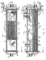
- evaporator 16 has a shell 22 in which horizontally running tube bundle 24 is disposed.
- Tube bundle 24 is comprised of a plurality of tubes 26 through which a cooling medium flows.
- Such cooling medium which typically will be water, flows into evaporator 16 through an inlet 28 and flows thereoutof through an outlet 30.
- evaporator 16 is a one, three or other odd-numbered pass evaporator meaning that the flow of the cooling medium through the tube bundle down the length of the shell occurs once, thrice or another odd number of times.
- Outlet 30 could, however, be disposed on the same side of shell 22 as inlet 28 in which case the cooling medium would flow a first time down the length of the evaporator, would reverse direction and would flow a second time back through a different portion of the tubes of the evaporator tube bundle. Such flow would make evaporator 16 a two-pass evaporator. Other even-numbered multiples of passes are likewise possible.
- the cooling medium that flows through tubes 26 of tube bundle 24 of evaporator 16 will be cooled by its rejection of the heat it carries to the refrigerant that flows into evaporator shell 22 exterior of such tubes.
- the cooling medium then returns, in a cooled state, from evaporator 16 to the heat load which it is the purpose of chiller 10 to cool.
- two-phase refrigerant is delivered into shell 22 of evaporator 16 through inlet piping 32.
- Inlet piping 32 delivers two-phase refrigerant into liquid-vapor separator 34.
- liquid-vapor separator 34 is disposed internal of shell 22, generally at one end thereof. Liquid-vapor separator 34 could, however, be located external of shell 22.
- Liquid-vapor separator 34 is configured and acts generally to separate the vapor portion of the two-phase refrigerant mixture that is delivered into it from the liquid portion of that mixture.
- the purpose of employing separator 34 is to reduce the velocity of the liquid portion of that mixture and to cause that liquid refrigerant, together with any lubricant carried therewith, to be deposited from above, in low-velocity droplet form, generally onto one end of surface 36 of the liquid pool 38 that is found in shell 22.
- Separator 34 has the further purpose of preventing the carryover of liquid refrigerant, in mist form, out of the evaporator by its removal and direction of the vapor portion of the two-phase mixture into the upper region of shell 22, away from the location where the liquid portion of the mixture is deposited onto pool 38.
- Apparatus other than a liquid-vapor separator to accomplish the deposit of liquid onto the surface of pool 38 are contemplated as falling within the scope of the present invention. Overall, however, use of a liquid-vanor separator is preferred for the reason that it causes the delivery from above of liquid refrigerant and any oil carried with it onto the surface of pool 38 in a manner which tends not to release a mist into the interior of the shell above the level of the liquid pool.
- Separator 34 and/or the location at which the liquid portion of the two-phase mixture delivered into the separator is delivered into pool 38 is, in the Figure 2 embodiment, generally at one end thereof.
- lubricant that is carried into the evaporator with the system refrigerant.
- the vapor which is separated and delivered into the upper region of shell 22 by liquid-vapor separator 34, together with the vapor that is created by the heat exchange that occurs within pool 38, is drawn to the opposite end of shell 22 and into inlet 44 of compressor suction line 40, generally with little liquid content.
- a baffle or shield 42 may be disposed intermediate surface 36 of pool 38 and the inlet 44 to suction line 40 so as to inhibit the entry of liquid in mist and/or droplet form thereinto.
- surface 36 of pool 38 is nominally maintained just above the top of the upper tubes in tube bundle 24 so that under typical operating conditions all or at least the majority of the tubes of the tube bundle are immersed in pool 38.
- An oil blockoff baffle 46 is disposed, in the Figure 2 embodiment, within the liquid pool at the end of shell 22 opposite the end at which liquid refrigerant and any oil carried with it is deposited, from above, into the pool.
- the height of baffle 46 in this embodiment is such that its upper edge 48 will generally be from two to six inches above the nominal level of surface 36 of pool 38.
- tube sheet 50 and tube sheet 52 Disposed at the opposite ends of shell 22 are tube sheet 50 and tube sheet 52. Each is penetrated by the ends of tubes 26 of tube bundle 24. Also disposed at the ends of shell 22 are waterboxes 54 and 56. Inlet 28 to evaporator 16 connects into waterbox 54 while outlet 30 connects into waterbox 56.
- the evaporator illustrated in the Figure 2 embodiment is a three-pass evaporator.
- waterbox 54 has a partition 58 which restricts the cooling medium that flows into that waterbox through inlet 28 to flowing into the ends of the tubes 26 that constitute first portion 60 of tube bundle 24.
- the cooling medium flows through portion 60 of the tubes of tube bundle 24 and is then constrained by partition 62 of waterbox 56 at the other end of shell 22 to flow into second portion 64 of the tubes of tube bundle 24.
- Portion 64 of the tube bundle consists of those tubes whose ends open into waterbox 56 below partition 62 but above the tubes that constitute portion 60 of the tube bundle (see the dashed line 58a in Figure 5 below which portion 60 of the tube bundle is found). This causes the cooling medium to flow back through shell 22 a second time into waterbox 54.
- Partition 58 in water box 54 then, in turn, constrains the cooling medium that flows back to waterbox 54 to reverse flow direction again and to enter third portion 66 of tube bundle 24.
- Portion 66 of the tubes open into waterbox 58 above both partition 58 and above dashed line 62a in Figure 4.
- the medium then flows the length of shell 22 a third time, enters waterbox 56 and flows thereoutof through outlet 30. While the evaporator illustrated in Figure 2 is a three-pass evaporator, the number of passes is not critical and in no way constrains or limits the scope of the present invention.
- oil blockoff baffle 46 defines a plurality of apertures 72 as well as a cutout 74 and/or, if advantageous in a particular application, a plurality of peripheral cutouts 76a and/or secondary apertures 76b which are illustrated in phantom.
- Apertures 72 are penetrated one each by individual tubes 26 of tube bundle 24 while, if employed, a plurality of tubes penetrate cutout 74. If cutouts 76a and/or secondary apertures 76b are employed, they will not be penetrated by tubes.
- Baffle 46 may or not support the tubes of the tube bundle. If not, apertures 72 will be of a diameter which is slightly larger than the external diameter of the individual tubes 26 which pass therethrough.
- cutout 74 comprises the primary entrance for oil-bearing refrigerant into portion 90 of pool 38 that exists between baffle 46 and tube sheet 50 and from which oil-rich fluid is drawn out of the pool. If secondary cutouts 76a are employed baffle 46, they too will permit the flow of oil into portion 90 of pool 38. Similarly, if secondary apertures 76b are employed they will likewise admit lubricant into portion 90 of pool 38 and may, if properly located and if in sufficient number, be employed to the exclusion of cutout 74.
- Some oil may also flow into portion 90 through the annular spaces that surround the tubes which penetrate apertures 72 of the baffle if those apertures are sized so as to permit such flow. If the purpose of apertures 72 is only to support the tubes of the tube bundle, they will be sized for that purpose and the flow of oil through them will generally not occur.
- baffle 46 the flow of oil and liquid refrigerant into portion 90 of pool 38 is through baffle 46 and is sufficiently unrestricted to ensure that the level of surface 36 of pool 38 is generally the same on both sides of the baffle.
- This generally unrestricted flow through baffle 46 below the surface 36 of pool 38 causes lubricant to flow into portion 90 of pool 38 and prevents the unwanted concentration of oil upstream of the baffle and the associated interference of oil with the heat exchange that occurs between the relatively warm medium that flows through the tubes of the tube bundle and the portion of the liquid refrigerant in pool 38 upstream of baffle 46.
- baffle 46 is fabricated from an engineered material such as polypropylene.
- an outlet 78 is defined, in the preferred embodiment, in shell 22 intermediate blockoff baffle 46 and tube sheet 50 and is preferably disposed so as to communicate with the lower region of the portion of pool 38 in that location.
- Piping 80 runs from outlet 78 to apparatus 82, which is illustrated schematically as a pump, but could be an eductor or the like and which, when chiller 10 is in operation, motivates the flow of what will be an oil-rich mixture out of pool 38 via outlet 78. That mixture is delivered by apparatus 82 to compressor 18a of motor-compressor 18 via piping 84 or, alternatively, into suction line 40 via line 86 or into line 20a via line 88. Lines 86 and 88 are illustrated in phantom in Figure 1.
- liquid refrigerant will continuously vaporize along the length of tube bundle 24. That vapor bubbles to the surface 36 of pool 38 and is drawn upward, toward and into inlet 44 of suction piping 40, together with the vapor separated in liquid-vapor separator 34.
- the existence of lubricant in the pool adversely affects the heat transfer performance of the tubes immersed therein. This degradation is generally proportional to the concentration of the lubricant within the pool at a given location.
- concentration of lubricant in pool 38 rises in a direction away from the end of pool 38 onto which liquid refrigerant and oil is initially deposited, generally from less than 1% to about 2% at the upstream side of baffle 46.
- baffle 46 oil concentration upstream of baffle 46 will be relatively very low, generally averaging on the order of 2% or less in all such locations, and, more typically, on the order of 1%.
- oil concentration will, under most conditions, be at least two and more often on the order of three or more times higher.
- baffle 46 is disposed generally no more than 25% and preferably only from 10% to 15% or so of the length of shell 22 away from tube sheet 50, it will be appreciated that in the preferred embodiment about 85% to 90% of the surface area of the tubes that constitute tube bundle 24 is exposed to liquid refrigerant in which oil concentration is on the order of 1%. Because the majority of the surface area of tubes 26 of tube bundle 24 in the evaporator of the Figure 2 embodiment is exposed to relatively very low concentrations of oil, the overall thermal performance of evaporator 16 is excellent and is, in fact, superior to the thermal performance of typical flooded evaporators that are not configured to proactively manage lubricant flow.
- the evaporator of the embodiment of Figure 2 can be characterized as an atypical flooded evaporator in which the tube bundle is immersed in a liquid pool but in which the delivery of liquid refrigerant and any oil it contains into the interior of the evaporator shell is generally at one end thereof and is above the surface of the pool and the tube bundle therein.
- the cooling medium After passing through the tubes that constitute portion 60 of tube bundle 24, the cooling medium flows back through the length of shell 22 through portion 64 of the tubes that constitute tube bundle 24. Because the cooling medium will have been cooled to some degree by its initial flow through portion 60 of the tube bundle 24, the liquid refrigerant that surrounds the tubes that constitute second portion 64 of the tube bundle will experience some boiling and turbulence but not to the extent that the liquid surrounding the tubes that constitute portion 60 of the tube bundle will.
- the turbulence created in pool 38 when a multiple pass evaporator design is employed, generally occurs in a vertical/cross-sectional sense.
- This localized and controlled turbulence is generally beneath the surface of the liquid pool and is beneficial in that it creates vertical eddies which prevent the stagnation or concentration of oil in specific locations within pool 38 along the length thereof.
- Such eddies and the creation of such turbulence while not a necessity to the functioning of the evaporator of the present invention, is beneficial to its operation, to maintaining oil concentration low and uniform upstream of baffle 46 and, therefore, to the overall efficiency of evaporator 16.
- baffles 92 and 94 may be employed and are illustrated in phantom in Figures 2 and 3. Those baffles, the use of which may enhance evaporator performance but is not necessary, result in pool 38 not only developing a flow pattern which is axial, from one end of shell 22 to the other, but which is sinusoidal in nature.
- baffle 92 extends part-way across the width of shell 22 within pool 38 while baffle 94 does the same but extends from the opposite side of the shell.
- liquid flow within pool 38 proceeds generally from one end of shell 22 to the other, but also, referring to arrow 96, around baffle 92 toward a first side of shell 22 then back to the other side of the shell, around baffle 94. Finally, liquid flow will reach the opposite end of the shell where blockoff baffle 46 is located.
- the thermal efficiency of evaporator 18 can be enhanced to some degree for the reason that flow within pool 38 follows a non-linear path which prolongs the heat exchange contact of the liquid refrigerant within the pool with the tubes of the tube bundle.
- an oil-rich layer of foam 98 will generally be found to exist on the surface of portion 90 of pool 38 between baffle 46 and tube sheet 50 where oil concentration is high. Because baffle 46 extends several inches above the surface of pool 38, the existence of such foam is generally localized and limited to the surface of portion 90 of pool 38.
- a pipe 100 is illustrated in phantom in Figures 1, 2 and 3 which, in its preferred embodiment, is connected into the suction area of compressor 18a, downstream of motor 18c.
- pipe 100 can be connected into suction piping 40 as is indicated at 100a in Figures 1, 2 and 3.
- the open end 102 of pipe 100 is located at a predetermined height above surface 36 of pool 38, between baffle 46 and tube sheet 50 while the discharge end 104 of line 100 preferably connects to compressor 18a as is indicated in Figure 1.
- compressor 18a is a screw compressor
- line 100 connects to the area within the compressor through which suction gas flows enroute to the screw rotors.
- the height of foam layer 98 above surface 36 of pool 38 is a function of the concentration of oil in the refrigerant portion 90 of pool 38.
- the concentration of oil within portion 90 of pool 38 can generally be maintained at a predetermined level. If oil concentration comes to be low, the foam layer 98 will fall below the open end 102 of pipe 100 with the result that the withdrawal of oil from pool 38 will decrease or cease and refrigerant gas only will be drawn out of the evaporator through pipe 100. Oil concentration within portion 90 of pool 38 will, as a result, increase. As oil concentration increases, the thickness of the foam layer in portion 90 of pool 38 increases until open end 102 pipe 100 comes to be disposed within it. At that time, oil-rich foam is once again drawn out of the evaporator by the compressor and is delivered into the suction area of the compressor.
- the concentration of oil within portion 90 of pool 38 is self-regulated in a manner which maintains it generally constant and the amount of oil which is returned to the compressor becomes a function of the overall system oil circulation rate. Further, by use of this oil return system, the need for a pump by which to return oil to the system compressor is eliminated in favor of using suction gas in the normal course of its return to the compressor. Still further, the need for proactive control and/or the use of controls in the oil return process is eliminated.
- an optical sensor 106 can be placed in line 100 to detect the presence of foam.
- Sensor 106 may be a self-heated thermistor or some other device. In this manner, oil return can be monitored for chiller protection purposes but can also facilitate the detection of a low refrigerant charge.
- the expense of fabrication of the flowing pool evaporator of the present invention is less than that associated with most falling film designs, particularly as applied to smaller to medium-sized chillers where the size of the refrigerant charge is not so large as to offset the savings effected by the oil management achieved by the present invention.
- the evaporator of the embodiment of Figures 2-6 is particularly beneficial in terms of its use in evaporators and chillers of smaller to medium capacities, where the size and cost of the chiller's refrigerant charge is not, relatively speaking, large, a second embodiment of the flowing pool evaporator of the present invention, illustrated in Figures 7 and 8 and which may be preferred for use in chillers of medium to larger capacities, is disclosed.
- a second embodiment of the flowing pool evaporator of the present invention illustrated in Figures 7 and 8 and which may be preferred for use in chillers of medium to larger capacities.
- one-half or more of the tubes of tube bundle 24 reside above the surface 36 of pool 38 and preferably, in the range of 75% to 85% of the tubes of tube bundle 24 will reside above the pool surface. Because less than half of the tubes of tube bundle 24 are immersed in pool 38, because liquid refrigerant and any oil carried with it is generally uniformly distributed from above across the length and width of tube bundle 24 and because liquid refrigerant and any lubricant carried with it is deposited onto the top of the tube bundle in low energy droplet form, evaporator 16 of the Figure 7 embodiment functions similarly to a falling film evaporator from the standpoint of liquid distribution and thermal performance.
- refrigerant distributor 200 distributes liquid refrigerant and any lubricant carried with it in a generally uniform fashion across the length and width of the tube bundle.
- Piping 202, which connects into distributor 200, and compressor suction piping 204, which leads out of the interior of shell 22 to the chiller's compressor, can therefore be located essentially anywhere along the axial length of the evaporator shell.
- a catch pan 206 generally above surface 36 of pool 38 but below the tubes of tube bundle 24 that constitute the falling film portion of the tube bundle.
- imperfections in the uniformity of liquid distribution and/or downflow through the falling film portion of the evaporator would often result in unpredictable heat fluxes within the liquid pool 38 underlying that portion of the tube bundle and/or regions therein of high local oil concentration.
- an oil-rich foam often existed on most or the entirety of the surface 36 of pool 38. This layer of foam tended, at times and under certain chiller operating conditions, to rise upward into the falling film portion of the tube bundle and/or to be swept upward thereinto as refrigerant boiled out of pool 38.
- refrigerant distributor 200 which can be of a single or two-phase type, deposits liquid refrigerant onto the upper surface of tube bundle 24, generally across the length and width thereof and in a generally uniform fashion. A liquid film develops within the tube bundle and flows downward therethrough by force of gravity in the traditional falling film manner.
- catch pan 206 which constitutes both a physical barrier between the falling film portion of evaporator 16 and liquid pool 38 found in the lower portion thereof and apparatus for depositing liquid refrigerant and lubricant into pool 38 at a predetermined location.
- Catch pan 206 underlies the falling film portion of tube bundle 24 and runs generally the length of evaporator 16, terminating close to the interior surface of one of tube sheets 50 or 52. Because catch pan 206 slopes downward and/or is open at one end, the liquid that falls into it flows to the open and/or lower end of the catch pan and is deposited from above onto surface 36 of pool 38 at one end of the evaporator shell. Gravity is therefore employed to motivate the flow of liquid within the catch pan to one end of the evaporator shell.
- pool 38 in this embodiment operates in the manner which has been described with respect to the deposit of liquid into and the flow of liquid within pool 38 in the Figures 2-6 embodiment.
- lubricant-containing liquid is deposited out of catch pan 206 from above into pool 38 at a first end of the pool while oil outlet 78 is at the opposite end of the pool.
- Management of oil in this embodiment is independent of whether any foaming occurs on the surface of pool 38, whether any maldistribution of liquid refrigerant and oil from refrigerant distributor 206 or occurs or whether the flow of such liquid through the tube bundle above catch pan 206 is disrupted in a particular location. Further, because of the existence of catch pan 206 and the relatively much lower number of tubes that are subject to having their heat transfer performance degraded by immersion in pool 38 in this embodiment as compared to the embodiment of Figures 2-6, oil blockoff baffle 46 can be dispensed with although it could be employed and is illustrated in phantom in Figure 7 as is an oil foam return arrangement which includes pipe 100, previously described in the context of the Figures 1-6 embodiment.
- catch pan 206 the thermal performance of the evaporator is maximized under all conditions in a manner which is simple, reliable and relatively inexpensive but also in a manner which acts to reduce the size of the refrigerant charge required by the chiller in which it is employed.
Landscapes
- Engineering & Computer Science (AREA)
- Physics & Mathematics (AREA)
- Mechanical Engineering (AREA)
- Thermal Sciences (AREA)
- General Engineering & Computer Science (AREA)
- Heat-Exchange Devices With Radiators And Conduit Assemblies (AREA)
- Lubricants (AREA)
Claims (45)
- Rohrbündelverdampfer (16), umfassend:eine Ummantelung (22);einen Flüssigkeitsvorrat(38) in der Ummantelung (22), wobei die Flüssigkeit in dem Vorrat (38) Kühlflüssigkeit und Schmiermittel enthält;ein horizontal verlaufendes Rohrbündel (24) in der Ummantelung (22), wobei mindestens ein Teil der Rohre des Rohrbündels (24) in den Vorrat (38) zum Wärmeaustausch mit diesem eingetaucht ist;Vorrichtung (34) zum Abgeben von Flüssigkeit, welche Kühlflüssigkeit und Schmiermittel enthält, in den Vorrat (38) an einer ersten Vorratsposition,dadurch gekennzeichnet, dass die Vorrichtung (34) zum Abgeben von Flüssigkeit über der Oberfläche des Vorrats (38) angeordnet ist und Kühlflüssigkeit und Schmiermittel in den Vorrat (38) von oben her abgibt; und
einen Schmiermittelauslass (78), wobei der Schmiermittelauslass an einer zweiten Vorratsposition angeordnet ist, die abseits von der ersten Vorratsposition liegt und die eine Position ist, an die Schmiermittel in dem Vorrat (38) als Folge der Verdampfung von Kühlflüssigkeit aus dem Vorrat (38) strömt. - Rohrbündelverdampfer (16) nach Anspruch 1, wobei mindestens die Mehrheit der Rohre des Rohrbündels (24) in den Vorrat (38) eingetaucht ist.
- Verdampfer (16) nach Anspruch 2, wobei sich die erste Vorratsposition im Allgemeinen an einem Ende des Vorrats (38) und die zweite Vorratsposition sich im Allgemeinen an dem Ende des Vorrats (38) gegenüber dem einen Ende befinden.
- Verdampfer (16) nach Anspruch 3, ferner eine Vorrichtung umfassend, die in dem Vorrat zwischen der ersten und der zweiten Vorratsposition angeordnet ist, um das Schmiermittel zu veranlassen, sich nahe der zweiten Vorratsposition zu konzentrieren.
- Verdampfer (16) nach Anspruch 4, wobei der Schmiermittelauslass (78) mit dem Vorrat (38) unterhalb dessen Oberfläche (36)in Verbindung ist und wobei die Vorrichtung, um das Schmiermittel zu veranlassen, sich zu konzentrieren, ein Leitblech (46) umfasst, das durch mindestens den Teil der Rohre des Rohrbündels (24) durchdrungen wird, der in dem Vorrat (38) eingetaucht ist.
- Verdampfer nach Anspruch 5, wobei die Vorrichtung zum Abgeben von Flüssigkeit ein Flüssigkeits-Dampfabscheider (34) ist, wobei der Flüssigkeits-Dampfabscheider (34) verdampfte Kühlflüssigkeit in das Innere der Ummantelung oberhalb der Oberfläche (36) des Vorrats (38) abgibt.
- Verdampfer nach Anspruch 5, wobei sich das Leitblech (46) über die Oberfläche (36) des Vorrats (38) erstreckt und durch alle Rohre (26) des Rohrbündels (24) durchdrungen wird.
- Verdampfer nach Anspruch 5, wobei das Leitblech (46) mindestens drei Viertel der Länge des Vorrats weg vom Ende des Vorrats (38), wo sich die erste Vorratsposition befindet, angeordnet ist.
- Verdampfer nach Anspruch 8, wobei die Schmierstoffkonzentration in den mindestens drei Vierteln der Länge des Vorrats (38) weniger ist als die Hälfte der Schmierstoffkonzentration in dessen restlichem Viertel.
- Verdampfer nach Anspruch 5, wobei das Leitblech (46) mindestens 85 % der Länge des Vorrats (38) weg vom Ende des Vorrats (38), an welchem sich die erste Vorratsposition befindet, angeordnet ist und wobei die durchschnittliche Konzentration des Schmiermittels in den 85 % der Länge des Vorrats mindestens dreifach niedriger ist als die durchschnittliche Schmiermittelkonzentration im restlichen Vorrat (38).
- Verdampfer nach Anspruch 5, wobei das Leitblech (46) einen Ausschnitt definiert, der von mehr als einem der Rohre des Rohrbündels (24) durchdrungen ist, wobei der Ausschnitt der vorrangige Einlass für Schmiermittel in den Teil des Vorrats (38) ist, wo sich die zweite Vorratsposition befindet.
- Verdampfer nach Anspruch 5, wobei das Leitblech (46) eine oder mehrere Öffnungen definiert, welche nicht durch ein Rohr des Rohrbündels (24) durchdrungen sind.
- Verdampfer (16) nach Anspruch 5, ferner mindestens ein strömungslenkendes Leitblech umfassend, das dem Leitblech, das das Schmiermittel veranlasst, sich zu konzentrieren, vorausgeht, wobei das mindestens eine strömungslenkende Leitblech einen Strom in dem Vorrat vor dem Leitblech, das das Schmiermittel konzentriert, verursacht, um einem nichtlinearen Pfad in Richtung auf das Leitblech, das das Schmiermittel konzentriert, zu folgen, um so den Kontakt der Kühlflüssigkeit in dem Vorrat mit den Rohren des Rohrbündels (24) zu verlängern.
- Verdampfer nach Anspruch 1, wobei sich der Schmiermittelauslass (78) oberhalb der Oberfläche (36) des Vorrats (38) befindet.
- Verdampfer nach Anspruch 14, wobei sich die erste Vorratsposition im Allgemeinen an einem Ende des Vorrats (38) befindet und sich die zweite Vorratsposition im Allgemeinen am anderen Ende des Vorrats befindet, wobei der Schmiermittelauslass (78) an einer vorbestimmten Höhe über dem Vorrat (38)und im Allgemeinen über der zweiten Vorratsposition angeordnet ist.
- Verdampfer nach Anspruch 15, wobei die Rohre (26) des Rohrbündels (24) in dem Vorrat (38) eingetaucht sind.
- Verdampfer nach Anspruch 16, ferner ein Leitblech umfassend, das in dem Vorrat (38) zwischen der ersten und der zweiten Vorratsposition angeordnet ist, wobei das Leitblech näher an der zweiten Vorratsposition als an der ersten Vorratsposition angeordnet ist und von den Rohren des Rohrbündels (24) durchdrungen ist.
- Verdampfer nach Anspruch 17, wobei das Leitblech (46) mehrere Öffnungen definiert, die nicht von einem Rohr (26) des Rohrbündels (24) durchdrungen sind.
- Verdampfer nach Anspruch 1, wobei mindestens die Hälfte der Rohre (26) des Rohrbündels (24) über der Oberfläche des Vorrats (38) angeordnet sind und ferner einen Verteiler (200) umfassend, um Kühlflüssigkeit und Schmiermittel auf den Teil des Rohrbündels (24) abzugeben, der über der Oberfläche des Vorrats (38) angeordnet ist.
- Verdampfer nach Anspruch 19, wobei der Schmiermittelauslass (78) mit dem Vorrat (38) unterhalb dessen Oberfläche in Verbindung ist und wobei die erste Vorratsposition sich im Allgemeinen an einem Ende des Vorrats befindet und die zweite Vorratsposition sich im Allgemeinen am anderen Ende des Vorrats (38) befindet.
- Verdampfer nach Anspruch 20, wobei die Vorrichtung (34) zur Abgabe von Flüssigkeit unterhalb des Teils des Rohrbündels (24) liegt, welcher sich oberhalb der Oberfläche des Vorrats (38) befindet.
- Verdampfer nach Anspruch 21, wobei die Vorrichtung (34) zur Abgabe von Flüssigkeit Ränder entlang ihrer Länge aufweist, wobei die Ränder von den inneren Seiten der Ummantelung beabstandet sind, um so einen Strom von Kühlflüssigkeitsgas, das aus dem Vorrat (38) verdampft ist, nach oben weg und entlang der äußeren Seiten des Teils des Rohrbündels (24), der über der Oberfläche des Vorrats (38) angeordnet ist, zuzulassen.
- Verdampfer nach Anspruch 21, wobei der Verteiler fähig ist, eine Mischung aus zweiphasiger Kühlflüssigkeit und Schmiermittel in das Innere der Ummantelung (22) zu verteilen.
- Verdampfer (16) nach Anspruch 21, ferner eine Vorrichtung umfassend, die das Schmiermittel veranlasst, sich an der zweiten Vorratsposition zu konzentrieren.
- Verdampfer (16) nach Anspruch 24, wobei die Vorrichtung, die das Schmiermittel veranlasst, sich zu konzentrieren, ein Leitblech umfasst, wobei das Leitblech (48) in dem Vorrat (38) angeordnet ist und zwischen der ersten und der zweiten Vorratsposition angeordnet ist.
- Verdampfer (16) nach Anspruch 25, wobei das Leitblech (46) im Allgemeinen am Ende des Vorrats (38), wo sich die zweite Vorratsposition befindet, angeordnet ist und von den Rohren des Rohrbündels (24), die in dem Vorrat (38) eingetaucht sind, durchdrungen ist.
- Verdampfer nach Anspruch 19, wobei sich der Schmiermittelauslass (78) oberhalb der Oberfläche (36) des Vorrats (38) befindet.
- Kühlaggregat (10), umfassend:ein Rohrbündelverdampfer nach den Ansprüchen 1, 2,oder 3;einen Kompressor (18);einen Verflüssiger (12);ein Dehnungsbauteil (14);wobei der Verdampfer ferner umfasst:Vorrichtung zum Entfernen von Schmiermittel von dem Verdampfer (16), wobei die Vorrichtung zum Entfernen von Schmiermittel mit dem Schmiermittelauslass des Verdampfers (16) und mit dem Kompressor (18) in Verbindung ist.
- Kühlaggregat (10) nach Anspruch 28, ferner ein Leitblech (46) umfassend, um zu veranlassen, dass sich das Schmiermittel nahe der zweiten Vorratsposition konzentriert, wobei das Leitblech (46) von dem Teil der Rohre (26) des Rohrbündels (24) durchdrungen ist, der in dem Vorrat (38) eingetaucht ist.
- Kühlaggregat (10) nach Anspruch 29, wobei die Vorrichtung zum Abgeben von Flüssigkeit sich über dem Rohrbündel befindet und wobei der Schmiermittelauslass mit dem Vorrat (38) unterhalb dessen Oberfläche (36) in Verbindung ist.
- Kühlaggregat (10) nach Anspruch 29, wobei der Schmiermittelauslass mit dem Inneren der Ummantelung des Verdampfers (16) über der Oberfläche (36) des Vorrats (38) in Verbindung ist.
- Kühlaggregat (10) nach Anspruch 28, wobei mindestens die Hälfte der Rohre (26) des Rohrbündels (24) über der Oberfläche (36) des Vorrats (38) angeordnet sind und ferner einen Verteiler umfassend, der im Allgemeinen über der Länge und Breite des Teils des Rohrbündels (24), welches sich über der Oberfläche (36) des Vorrats befindet, angeordnet ist, wobei die Vorrichtung zum Abgeben von Flüssigkeit in den Vorrat (38) im Allgemeinen unterhalb der Länge und der Breite des Teils des Rohrbündels (24) angeordnet ist, welches sich über der Oberfläche des Vorrats (38) befindet.
- Kühlaggregat (10) nach Anspruch 32, wobei sich die erste Vorratsposition im Allgemeinen an einem Ende des Vorrats befindet, die zweite Vorratsposition sich im Allgemeinen am anderen Ende des Vorrats befindet und der Schmiermittelauslass unterhalb der Oberfläche des Vorrats und nahe der zweiten Vorratsposition angeordnet ist.
- Kühlaggregat (10) nach Anspruch 32, wobei sich die erste Vorratsposition im Allgemeinen an einem Ende des Vorrats befindet, die zweite Vorratsposition sich im Allgemeinen am anderen Ende des Vorrats befindet und der Schmiermittelauslass über der Oberfläche des Vorrats und nahe der zweiten Vorratsposition angeordnet ist.
- Flüssigkeits-Kühlaggregat (10) nach Anspruch 32, wobei die Vorrichtung zum Abgeben von Flüssigkeit eine Auffangwanne (206) umfasst, wobei die Auffangwanne (206) geneigt ist, um so Flüssigkeit in den Vorrat (38) an der ersten Vorratsposition abzugeben.
- Vorrichtung nach Anspruch 32, ferner ein Leitblech (46) umfassend, das in dem Vorrat (38) zwischen der ersten und der zweiten Vorratsposition angeordnet ist, wobei das Leitblech (46) das Schmiermittel veranlasst, sich nahe der zweiten Vorratsposition zu konzentrieren und von dem Teil der Rohre des Rohrbündels (24) durchdrungen ist, der unter der Oberfläche des Vorrats (38) angeordnet ist.
- Verfahren zum Rückführen von Schmiermittel von dem Rohrbündelverdampfer eines Kühlaggregats, folgende Schritte umfassend:Aufrechterhalten eines Flüssigkeitsvorrats in dem Verdampfer, in den mindestens ein Teil der Rohre des Rohrbündels eingetaucht ist;Einfließen lassen von einer Mischung von Kühlflüssigkeit und Schmiermittel von der Dehnungsvorrichtung des Kühlaggregats in das Innere des Verdampfers;Abgeben, in dem Schritt des Einfließens, von Kühlflüssigkeit und Schmiermittel, welche im Inneren des Verdampfers aufgenommen sind, von oben auf die Oberfläche des Vorrats, im Allgemeinen an einer ersten Vorratsposition;Verdampfen lassen von Kühlflüssigkeit aus dem Vorrat, um so Schmiermittel zu veranlassen, von der ersten Vorratsposition weg zu einer zweiten Vorratsposition in dem Vorrat, welche entfernt von der ersten Vorratsposition liegt, zu strömen; undEntnehmen von Schmiermittel aus dem Vorrat nahe der zweiten Vorratsposition.
- Verfahren nach Anspruch 37, den weiteren Schritt umfassend, das Schmiermittel zu veranlassen, sich nahe der zweiten Vorratsposition zu konzentrieren.
- Verfahren nach Anspruch 38, wobei mindestens die Mehrheit der Rohre des Rohrbündels des Verdampfers in dem Vorrat eingetaucht sind und wobei der Schritt des Konzentrierens den Schritt umfasst, ein Leitblech, das von dem Teil der Rohre des Rohrbündels durchdrungen ist, der in dem Vorrat eingetaucht ist, zwischen der ersten und der zweiten Vorratsposition einzusetzen.
- Verfahren nach Anspruch 39, wobei der Schritt des Abscheidens die Schritte des Abscheidens von Schmiermittel von dem Vorrat unterhalb dessen Oberfläche und das Zuführen des abgeschiedenen Schmiermittels an den Kompressor des Kühlaggregats umfasst.
- Verfahren nach Anspruch 39, wobei der Schritt des Abscheidens den Schritt des Abscheidens von Schmiermittel von dem Vorrat oberhalb dessen Oberfläche und das Zuführen des abgeschiedenen Schmiermittels an den Kompressor des Kühlaggregats umfasst.
- Verfahren nach Anspruch 38, wobei die Mehrheit der Rohre des Rohrbündels des Verdampfers über der Oberfläche des Vorrats angeordnet sind und ferner die Schritte umfassend, Flüssigkeit, welche Kühlflüssigkeit und Schmiermittel umfasst, im Allgemeinen über die Länge und Breite des oberen Teils des Rohrbündels, der sich über der Oberfläche des Vorrats befindet, zu verteilen und, noch vor dem Schritt des Verteilens, Kühlflüssigkeit und Schmiermittel, welche nach unten durch den Teil des Rohrbündels geströmt sind, welcher sich über der Oberfläche des Vorrats befindet, zu sammeln.
- Verfahren nach Anspruch 42, wobei der Schritt des Abscheidens den Schritt des Abscheidens von Schmiermittel von dem Vorrat unterhalb dessen Oberfläche und das Zuführen des abgeschiedenen Schmiermittels an den Kompressor des Kühlaggregats umfasst.
- Verfahren nach Anspruch 42, wobei der Schritt des Abscheidens den Schritt des Abscheidens von Schmiermittel von dem Vorrat oberhalb dessen Oberfläche und das Zuführen des abgeschiedenen Schmiermittels an den Kompressor des Kühlaggregats umfasst.
- Verfahren nach Anspruch 38, wobei der Schritt des Abscheidens die Schritte des Abscheidens von schmiermittelreichem Schaum von der Oberfläche des Vorrats von einer Position über der Oberfläche des Vorrats und das Zuführen von mindestens dem Schmiermittelanteil des Schaums an den Kompressor umfasst.
Applications Claiming Priority (3)
| Application Number | Priority Date | Filing Date | Title |
|---|---|---|---|
| US09/849,557 US6516627B2 (en) | 2001-05-04 | 2001-05-04 | Flowing pool shell and tube evaporator |
| US849557 | 2001-05-04 | ||
| PCT/US2002/014974 WO2003001130A2 (en) | 2001-05-04 | 2002-05-02 | Flowing pool shell and tube evaporator |
Publications (2)
| Publication Number | Publication Date |
|---|---|
| EP1518077A2 EP1518077A2 (de) | 2005-03-30 |
| EP1518077B1 true EP1518077B1 (de) | 2007-07-11 |
Family
ID=25305988
Family Applications (1)
| Application Number | Title | Priority Date | Filing Date |
|---|---|---|---|
| EP02780873A Expired - Lifetime EP1518077B1 (de) | 2001-05-04 | 2002-05-02 | Strömungsbad-rohrbündelverdampfer |
Country Status (6)
| Country | Link |
|---|---|
| US (1) | US6516627B2 (de) |
| EP (1) | EP1518077B1 (de) |
| JP (1) | JP3943542B2 (de) |
| CN (1) | CN100447504C (de) |
| CA (1) | CA2439476C (de) |
| WO (1) | WO2003001130A2 (de) |
Cited By (2)
| Publication number | Priority date | Publication date | Assignee | Title |
|---|---|---|---|---|
| US9644905B2 (en) | 2012-09-27 | 2017-05-09 | Hamilton Sundstrand Corporation | Valve with flow modulation device for heat exchanger |
| US11739988B2 (en) | 2019-12-03 | 2023-08-29 | Carrier Corporation | Flooded evaporator |
Families Citing this family (65)
| Publication number | Priority date | Publication date | Assignee | Title |
|---|---|---|---|---|
| JP3785143B2 (ja) * | 2000-11-24 | 2006-06-14 | 三菱重工業株式会社 | 冷凍機用蒸発器及び冷凍装置 |
| US8463441B2 (en) | 2002-12-09 | 2013-06-11 | Hudson Technologies, Inc. | Method and apparatus for optimizing refrigeration systems |
| US6904759B2 (en) * | 2002-12-23 | 2005-06-14 | Carrier Corporation | Lubricant still and reservoir for refrigeration system |
| US7073572B2 (en) * | 2003-06-18 | 2006-07-11 | Zahid Hussain Ayub | Flooded evaporator with various kinds of tubes |
| US7395678B2 (en) * | 2004-04-02 | 2008-07-08 | Parker-Hannifin Corp. | Refrigerant receiving apparatus |
| US6868695B1 (en) * | 2004-04-13 | 2005-03-22 | American Standard International Inc. | Flow distributor and baffle system for a falling film evaporator |
| EP1780479A4 (de) * | 2004-07-01 | 2013-12-11 | Daikin Ind Ltd | Gefriervorrichtung und klimaanlage |
| KR100903685B1 (ko) * | 2004-10-13 | 2009-06-18 | 요크 인터내셔널 코포레이션 | 유하액막(遊下液漠) 증발기 |
| CN101194133A (zh) * | 2005-04-06 | 2008-06-04 | 株式会社前川制作所 | 满液式蒸发器 |
| EP1886077A1 (de) * | 2005-05-30 | 2008-02-13 | Johnson Controls Denmark ApS | Öltrennung in einem kühlkreislauf |
| US20070095512A1 (en) * | 2005-10-31 | 2007-05-03 | Wei Chen | Shell and tube evaporator |
| US7337630B2 (en) * | 2005-11-10 | 2008-03-04 | Johnson Controls Technology Company | Compact evaporator for chiller application |
| US20070107886A1 (en) * | 2005-11-14 | 2007-05-17 | Wei Chen | Evaporator for a refrigeration system |
| US20070235173A1 (en) * | 2006-04-10 | 2007-10-11 | Aaf-Mcquary Inc. | Shell and tube evaporator |
| US8187370B2 (en) * | 2006-07-13 | 2012-05-29 | Shi-Apd Cryogenics, Inc. | Horizontal bulk oil separator |
| WO2008045039A1 (en) * | 2006-10-10 | 2008-04-17 | Carrier Corporation | Dual-circuit chiller with two-pass heat exchanger in a series counterflow arrangement |
| WO2008045040A2 (en) * | 2006-10-10 | 2008-04-17 | Carrier Corporation | Dual-circuit series counterflow chiller with intermediate waterbox |
| EP2097687A2 (de) * | 2006-12-21 | 2009-09-09 | Johnson Controls Technology Company | Dünnschichtverdampfer mit haube und flussverteiler |
| TWI320094B (en) * | 2006-12-21 | 2010-02-01 | Spray type heat exchang device | |
| US7421855B2 (en) * | 2007-01-04 | 2008-09-09 | Trane International Inc. | Gas trap distributor for an evaporator |
| US7707850B2 (en) * | 2007-06-07 | 2010-05-04 | Johnson Controls Technology Company | Drainage mechanism for a flooded evaporator |
| US20090165497A1 (en) * | 2007-12-31 | 2009-07-02 | Johnson Controls Technology Company | Heat exchanger |
| EP2232166B1 (de) | 2008-01-11 | 2012-04-18 | Johnson Controls Technology Company | Dampfkompressionssystem |
| TWI358520B (en) * | 2008-12-04 | 2012-02-21 | Ind Tech Res Inst | Pressure-adjustable multi-tube spraying device |
| KR20110004152A (ko) | 2009-07-07 | 2011-01-13 | 엘지전자 주식회사 | 공기조화기 |
| EP2457051A2 (de) * | 2009-07-22 | 2012-05-30 | Johnson Controls Technology Company | Kompakter vedampfer für kühlaggregate |
| US20110056664A1 (en) * | 2009-09-08 | 2011-03-10 | Johnson Controls Technology Company | Vapor compression system |
| KR20110097367A (ko) * | 2010-02-25 | 2011-08-31 | 엘지전자 주식회사 | 칠러 |
| KR101633781B1 (ko) * | 2010-03-05 | 2016-06-27 | 엘지전자 주식회사 | 칠러 |
| US10209013B2 (en) | 2010-09-03 | 2019-02-19 | Johnson Controls Technology Company | Vapor compression system |
| US9062900B2 (en) * | 2010-11-08 | 2015-06-23 | Honeywell International Inc. | Integrated evaporator and accumulator for refrigerant systems |
| CN102003851A (zh) * | 2010-12-15 | 2011-04-06 | 广州联合冷热设备有限公司 | 一种满液式蒸发器结构 |
| JP5802397B2 (ja) * | 2011-01-31 | 2015-10-28 | 独立行政法人石油天然ガス・金属鉱物資源機構 | 温度制御システム |
| US9513059B2 (en) | 2011-02-04 | 2016-12-06 | Lockheed Martin Corporation | Radial-flow heat exchanger with foam heat exchange fins |
| WO2012106603A2 (en) | 2011-02-04 | 2012-08-09 | Lockheed Martin Corporation | Shell-and-tube heat exchangers with foam heat transfer units |
| WO2012106605A2 (en) | 2011-02-04 | 2012-08-09 | Lockheed Martin Corporation | Staged graphite foam heat exchangers |
| US20140034275A1 (en) * | 2011-04-21 | 2014-02-06 | Carrier Corporation | Condenser/Accumulator and Systems and Operation Methods |
| US20130048258A1 (en) * | 2011-08-26 | 2013-02-28 | Yung-Sho Yang | Shell-and-tube heat exchanger |
| US20140223936A1 (en) | 2011-09-26 | 2014-08-14 | Trane International Inc. | Refrigerant management in hvac systems |
| US9746256B2 (en) * | 2011-11-18 | 2017-08-29 | Carrier Corporation | Shell and tube heat exchanger with a vapor port |
| EP2807439B1 (de) | 2012-01-27 | 2017-08-23 | Carrier Corporation | Verdampfer und flüssigkeitsverteiler |
| US9513039B2 (en) * | 2012-04-23 | 2016-12-06 | Daikin Applied Americas Inc. | Heat exchanger |
| US20130277020A1 (en) * | 2012-04-23 | 2013-10-24 | Aaf-Mcquay Inc. | Heat exchanger |
| US9541314B2 (en) * | 2012-04-23 | 2017-01-10 | Daikin Applied Americas Inc. | Heat exchanger |
| US9671146B2 (en) | 2013-01-25 | 2017-06-06 | Trane International Inc. | Refrigerant cooling and lubrication system with refrigerant vapor vent line |
| US10317114B2 (en) | 2013-06-13 | 2019-06-11 | Trane International Inc. | Methods and systems of streaming refrigerant in a heat exchanger |
| US10222105B2 (en) | 2014-01-15 | 2019-03-05 | Carrier Corporation | Refrigerant distributor for falling film evaporator |
| JP2015194302A (ja) * | 2014-03-31 | 2015-11-05 | 荏原冷熱システム株式会社 | ターボ冷凍機 |
| WO2016004390A2 (en) * | 2014-07-02 | 2016-01-07 | Evapco, Inc. | Low charge packaged refrigeration system |
| US10670312B2 (en) * | 2015-06-10 | 2020-06-02 | Lockheed Martin Corporation | Evaporator having a fluid distribution sub-assembly |
| US9869496B2 (en) * | 2015-08-27 | 2018-01-16 | Stellar Refrigeration Contracting, Inc. | Liquid chiller system |
| FR3042858B1 (fr) * | 2015-10-21 | 2018-01-12 | Technip France | Dispositif d'echange thermique entre un premier fluide destine a etre vaporise et un deuxieme fluide destine a etre refroidi et/ou condense, installation et procede associes |
| CN105509373A (zh) * | 2015-12-24 | 2016-04-20 | 珠海格力电器股份有限公司 | 换热器及具有其的空调器 |
| CN108662812B (zh) | 2017-03-31 | 2022-02-18 | 开利公司 | 流平衡器和具有该流平衡器的蒸发器 |
| CN111373213B (zh) | 2017-09-25 | 2022-04-05 | 江森自控科技公司 | 两级油动力喷射器系统 |
| US11656036B2 (en) * | 2019-03-14 | 2023-05-23 | Carrier Corporation | Heat exchanger and associated tube sheet |
| US11982475B2 (en) * | 2019-05-07 | 2024-05-14 | Carrier Corporation | Refrigerant lubrication system with side channel pump |
| FR3097313B1 (fr) * | 2019-06-17 | 2021-10-01 | Naval Energies | Évaporateur d’un fluide de travail pour une centrale ETM, comportant notamment un système d’amortissement |
| FR3097308B1 (fr) * | 2019-06-17 | 2021-11-05 | Naval Energies | Évaporateur d’un fluide de travail pour une centrale ETM comportant un système d’aspersion adaptée |
| JP6783369B2 (ja) * | 2019-11-07 | 2020-11-11 | 三菱重工サーマルシステムズ株式会社 | 熱交換システム |
| US11988422B2 (en) | 2021-04-28 | 2024-05-21 | Carrier Corporation | Microchannel heat exchanger drain |
| CN115493306A (zh) * | 2021-06-17 | 2022-12-20 | 开利公司 | 制冷系统和用于其的回油方法 |
| DE102021119867A1 (de) * | 2021-07-30 | 2023-02-02 | KMU LOFT Cleanwater SE | Wärmetauscher, Verfahren zum Betreiben eines Wärmetauschers und Prozesswasserdestillationsanlage |
| CN116734652A (zh) * | 2022-03-09 | 2023-09-12 | 开利公司 | 用于热交换器的非金属隔板 |
| US12066224B2 (en) * | 2022-06-03 | 2024-08-20 | Trane International Inc. | Evaporator charge management and method for controlling the same |
Family Cites Families (13)
| Publication number | Priority date | Publication date | Assignee | Title |
|---|---|---|---|---|
| US1899378A (en) * | 1926-10-20 | 1933-02-28 | Servel Inc | Method of and apparatus for separating a liquid from other liquids |
| US2535996A (en) | 1946-02-27 | 1950-12-26 | Lummus Co | Evaporator |
| GB622043A (en) | 1947-03-05 | 1949-04-26 | Lightfoot Refrigeration Compan | Improvements in or relating to compression refrigeration systems |
| US3789617A (en) | 1972-01-13 | 1974-02-05 | Thermocycle Inc | Thermodynamic system |
| SE458149B (sv) | 1984-07-05 | 1989-02-27 | Stal Refrigeration Ab | Koeldmediefoeraangare foer kylsystem |
| WO1994023252A1 (en) * | 1993-03-31 | 1994-10-13 | American Standard Inc. | Cooling of compressor lubricant in a refrigeration system |
| US5588596A (en) | 1995-05-25 | 1996-12-31 | American Standard Inc. | Falling film evaporator with refrigerant distribution system |
| US5761914A (en) * | 1997-02-18 | 1998-06-09 | American Standard Inc. | Oil return from evaporator to compressor in a refrigeration system |
| US6167713B1 (en) | 1999-03-12 | 2001-01-02 | American Standard Inc. | Falling film evaporator having two-phase distribution system |
| US6170286B1 (en) * | 1999-07-09 | 2001-01-09 | American Standard Inc. | Oil return from refrigeration system evaporator using hot oil as motive force |
| US6233967B1 (en) * | 1999-12-03 | 2001-05-22 | American Standard International Inc. | Refrigeration chiller oil recovery employing high pressure oil as eductor motive fluid |
| US6293112B1 (en) * | 1999-12-17 | 2001-09-25 | American Standard International Inc. | Falling film evaporator for a vapor compression refrigeration chiller |
| US6341492B1 (en) * | 2000-05-24 | 2002-01-29 | American Standard International Inc. | Oil return from chiller evaporator |
-
2001
- 2001-05-04 US US09/849,557 patent/US6516627B2/en not_active Expired - Lifetime
-
2002
- 2002-05-02 JP JP2003507484A patent/JP3943542B2/ja not_active Expired - Fee Related
- 2002-05-02 WO PCT/US2002/014974 patent/WO2003001130A2/en not_active Ceased
- 2002-05-02 CA CA002439476A patent/CA2439476C/en not_active Expired - Fee Related
- 2002-05-02 EP EP02780873A patent/EP1518077B1/de not_active Expired - Lifetime
- 2002-05-02 CN CNB028072332A patent/CN100447504C/zh not_active Expired - Lifetime
Non-Patent Citations (1)
| Title |
|---|
| None * |
Cited By (2)
| Publication number | Priority date | Publication date | Assignee | Title |
|---|---|---|---|---|
| US9644905B2 (en) | 2012-09-27 | 2017-05-09 | Hamilton Sundstrand Corporation | Valve with flow modulation device for heat exchanger |
| US11739988B2 (en) | 2019-12-03 | 2023-08-29 | Carrier Corporation | Flooded evaporator |
Also Published As
| Publication number | Publication date |
|---|---|
| EP1518077A2 (de) | 2005-03-30 |
| WO2003001130A3 (en) | 2005-02-03 |
| US6516627B2 (en) | 2003-02-11 |
| WO2003001130A2 (en) | 2003-01-03 |
| CA2439476C (en) | 2007-03-06 |
| CN1500193A (zh) | 2004-05-26 |
| JP3943542B2 (ja) | 2007-07-11 |
| JP2005502016A (ja) | 2005-01-20 |
| CN100447504C (zh) | 2008-12-31 |
| US20020162352A1 (en) | 2002-11-07 |
| CA2439476A1 (en) | 2003-01-03 |
Similar Documents
| Publication | Publication Date | Title |
|---|---|---|
| CA2439476C (en) | Flowing pool shell and tube evaporator | |
| US5419155A (en) | Cooling of compressor lubricant in a refrigeration system condenser | |
| EP1242773B1 (de) | Fallfilmverdampfer für eine dampfkompressionskühlanlage | |
| KR100623105B1 (ko) | 스크류 압축 냉각기를 위한 오일 회수 및 윤활 시스템 | |
| EP2841867B1 (de) | Wärmetauscher | |
| US11137183B2 (en) | Phobic/philic structures in refrigeration systems and liquid vapor separation in refrigeration systems | |
| US3232073A (en) | Heat pumps | |
| US5636520A (en) | Method of removing an immiscible lubricant from an refrigeration system | |
| JP2004524497A (ja) | 蒸気及び液体を排出する装置及び方法 | |
| US3304741A (en) | Oil separator arrangement for a refrigeration system | |
| EP1583595B1 (de) | Schmiermittelverdampfer und behälter für eine kälteanlage | |
| JP2000179975A (ja) | 多段蒸発吸収型の吸収冷温水機及びそれを備えた大温度差空調システム | |
| EP0676598B1 (de) | Kälteanlage mit Ölrückführung für Schraubenverdichter | |
| JP2004092928A (ja) | 凝縮器及び冷凍機 | |
| CN113294946A (zh) | 流体收集组件 | |
| CN113357850A (zh) | 蒸发器及冷水机组 | |
| EP4549843A1 (de) | Kondensatorbehälter, system und verfahren zur abscheidung von öl aus einer öl-kühlmittel-mischung | |
| JPH0979693A (ja) | 吸収式熱交換器 | |
| HK1205246B (en) | Heat exchanger |
Legal Events
| Date | Code | Title | Description |
|---|---|---|---|
| PUAI | Public reference made under article 153(3) epc to a published international application that has entered the european phase |
Free format text: ORIGINAL CODE: 0009012 |
|
| 17P | Request for examination filed |
Effective date: 20030909 |
|
| AK | Designated contracting states |
Kind code of ref document: A2 Designated state(s): FR GB |
|
| GRAP | Despatch of communication of intention to grant a patent |
Free format text: ORIGINAL CODE: EPIDOSNIGR1 |
|
| GRAS | Grant fee paid |
Free format text: ORIGINAL CODE: EPIDOSNIGR3 |
|
| GRAA | (expected) grant |
Free format text: ORIGINAL CODE: 0009210 |
|
| AK | Designated contracting states |
Kind code of ref document: B1 Designated state(s): FR GB |
|
| REG | Reference to a national code |
Ref country code: GB Ref legal event code: FG4D |
|
| ET | Fr: translation filed | ||
| PLBE | No opposition filed within time limit |
Free format text: ORIGINAL CODE: 0009261 |
|
| STAA | Information on the status of an ep patent application or granted ep patent |
Free format text: STATUS: NO OPPOSITION FILED WITHIN TIME LIMIT |
|
| 26N | No opposition filed |
Effective date: 20080414 |
|
| REG | Reference to a national code |
Ref country code: FR Ref legal event code: PLFP Year of fee payment: 15 |
|
| REG | Reference to a national code |
Ref country code: FR Ref legal event code: PLFP Year of fee payment: 16 |
|
| REG | Reference to a national code |
Ref country code: FR Ref legal event code: PLFP Year of fee payment: 17 |
|
| PGFP | Annual fee paid to national office [announced via postgrant information from national office to epo] |
Ref country code: FR Payment date: 20210421 Year of fee payment: 20 |
|
| PGFP | Annual fee paid to national office [announced via postgrant information from national office to epo] |
Ref country code: GB Payment date: 20210422 Year of fee payment: 20 |
|
| REG | Reference to a national code |
Ref country code: GB Ref legal event code: PE20 Expiry date: 20220501 |
|
| PG25 | Lapsed in a contracting state [announced via postgrant information from national office to epo] |
Ref country code: GB Free format text: LAPSE BECAUSE OF EXPIRATION OF PROTECTION Effective date: 20220501 |