EP1517848B1 - Rollenanordnung für einen staurollenförderer - Google Patents
Rollenanordnung für einen staurollenförderer Download PDFInfo
- Publication number
- EP1517848B1 EP1517848B1 EP03735140A EP03735140A EP1517848B1 EP 1517848 B1 EP1517848 B1 EP 1517848B1 EP 03735140 A EP03735140 A EP 03735140A EP 03735140 A EP03735140 A EP 03735140A EP 1517848 B1 EP1517848 B1 EP 1517848B1
- Authority
- EP
- European Patent Office
- Prior art keywords
- roller
- conveyor
- clutch
- roller shaft
- clutch part
- Prior art date
- Legal status (The legal status is an assumption and is not a legal conclusion. Google has not performed a legal analysis and makes no representation as to the accuracy of the status listed.)
- Expired - Lifetime
Links
Images


Classifications
-
- B—PERFORMING OPERATIONS; TRANSPORTING
- B65—CONVEYING; PACKING; STORING; HANDLING THIN OR FILAMENTARY MATERIAL
- B65G—TRANSPORT OR STORAGE DEVICES, e.g. CONVEYORS FOR LOADING OR TIPPING, SHOP CONVEYOR SYSTEMS OR PNEUMATIC TUBE CONVEYORS
- B65G13/00—Roller-ways
- B65G13/02—Roller-ways having driven rollers
- B65G13/06—Roller driving means
- B65G13/073—Roller driving means comprising free-wheel gearing
-
- B—PERFORMING OPERATIONS; TRANSPORTING
- B65—CONVEYING; PACKING; STORING; HANDLING THIN OR FILAMENTARY MATERIAL
- B65G—TRANSPORT OR STORAGE DEVICES, e.g. CONVEYORS FOR LOADING OR TIPPING, SHOP CONVEYOR SYSTEMS OR PNEUMATIC TUBE CONVEYORS
- B65G47/00—Article or material-handling devices associated with conveyors; Methods employing such devices
- B65G47/22—Devices influencing the relative position or the attitude of articles during transit by conveyors
- B65G47/26—Devices influencing the relative position or the attitude of articles during transit by conveyors arranging the articles, e.g. varying spacing between individual articles
- B65G47/261—Accumulating articles
Definitions
- the invention relates to a roller assembly for a Staurollen intensiveer, as this in the The preambles of claims 1 and 28, and an accumulating roller conveyor, as this in the preamble of claim 34 is described.
- Sloppy roller conveyors are often used for unpressurized storage and conveying of piece goods used and have rotatably mounted conveyor rollers, which combined into conveyor zones are, wherein in each conveying zone, a roller assembly a drivable and optionally brakeable conveyor roller is provided.
- From EP 1 132 321 A is a accumulation roller conveyor with a plurality of in a support frame held conveyor rollers, which are assigned to several conveyor zones and in each conveyor zone a drivable and brakable conveyor roller is associated with the other roles of the same Conveying zone is coupled, known.
- the drivable and brakable conveyor rollers are open each held a fixed roller axle, on which a drive roller is arranged, the can be coupled via an electromechanical coupling with the driveable and brakable conveyor roller is, which in turn is provided with an electromechanical braking device.
- the one each delivery zone and via the electromechanical coupling with the and brakable conveyor pulley detachable drive pulley is with one extending over the length of the Stolling roller conveyor extending endlessly circulating drive member, e.g. Belt, chain, in Drive connection.
- the electromechanical coupling is by one with the roller axle rotatably connected ring magnet and a rotationally fixed with the drivable and braked conveyor roller formed connected and axially displaceable held on this anchor.
- the coupling and brake means becomes over, occupying the occupancy state of each delivery zone Sensors, e.g. in the path of movement of piece goods protruding switching flaps, optical Light barriers etc., controlled.
- roller assembly for conveying a piece goods along a Staurollen alreadyers is known from US 5,810,157 A.
- the roller assembly has a driven shaft, an inner sleeve mounted thereon and one on top of this sleeve Frictional element attached conveyor roller and a screw thread arrangement on the inner sleeve axially adjustable lock nut on.
- the locknut is with a clamping ring and the inner sleeve provided with a radially circumferential projection.
- the projection and the clamping ring have complementary to each other and formed with each other engaged friction surfaces.
- a cylindrical surface of the clamping ring adjoins an inner surface of the conveyor roller.
- the friction between the inner Sleeve and the conveyor roller is a function of the weight of the transported piece goods a, so with increasing weight of the piece goods, the frictional force between the inner Sleeve and the conveyor roller also increases and the conveyor roller together with the inner Sleeve and the shaft is driven.
- the engagement of the clamping ring with the inner surface of the conveyor roller generates a further frictional engagement or a frictional force, the regardless of the weight of the transported piece goods, therefore, if the cargo along the accumulation roller conveyor is moved, is set.
- From DE 37 20 609 A and DE 2 117 959 A is a roller assembly for a accumulation roller conveyor the one in a support frame of the accumulation roller conveyor on a fixed Roller axle rotatably mounted, drivable conveyor roller and one on one side of the roller arranged drive wheel, in particular a sprocket, as well as between the conveyor roller and the drive wheel from a certain torque slipping of the conveyor roller opposite the drive wheel permitting coupling with two relatively adjustable coupling parts having.
- DE 37 20 609 A is one of the coaxial coupling parts with a conical contact surface provided with a coaxial recess with conical Inner surface of the other coupling part is engageable.
- the at least one, on the Roller axis axially movable coupling part is via a spring element against the other Clutch part pressed.
- the transmittable friction torque from the sprocket to the conveyor roller depends essentially on the bias of the spring element.
- EP 0 372 854 A1 discloses a roller arrangement which has a support frame rotatably mounted shaft and a rotatably connected to the shaft conveyor roller and a on the shaft rotatably mounted sprocket and a coupling device between the Shaft and the sprocket has.
- the coupling device is designed as a slip clutch and has two mutually frictionally engaged coupling parts with complementary trained coupling surfaces.
- the first coupling part is arranged coaxially with the shaft and rotatably connected to the drive wheel and the second coupling part on the shaft arranged axially adjustable.
- the coupling surface of the second coupling part is against pressed the coupling surface of the first coupling part with a constant spring force. If a torque value set to the spring force is exceeded, the frictional engagement becomes between the two coupling parts solved and slips the first coupling part through the second coupling part.
- a roller arrangement for a accumulating roller conveyor is known from the further DE 25 19 374 A, the arranged on a fixed roller axle drive wheel and one of this Having on a jaw clutch on and uncoupled conveyor roller.
- the clutch includes a by a clutch lever axially displaceable to the roller axis coupling member and a counter-coupling member.
- the present invention is based on the object, a roller assembly for a Staurollenminuteer to create, with the known from the prior art disadvantage of high switching force for the actuation of the clutch device avoided and the drive torque is reliably transmitted from the drive roller to the conveyor roller, and the characterized by a simple structure. Regardless, it is the object of the invention To make better use of the already existing space in the drive and conveyor roller and should a use of the roller assembly allows unrestricted even under the most difficult conditions become.
- the object of the invention is represented by the recited in the characterizing part of claim 1 Characteristics solved.
- the surprising advantages are that between the conveyor roller and the first coupling part is a load torque-dependent and self-adjusting adjusting device is arranged, over which the first coupling part with one to the minimum weight of the piece goods to be transported, low spring force exceeded, on the weight of the piece goods to be transported adjusting pressure force against the other Clutch part can be pressed, whereby on the one hand a slip-free engagement between the coupling parts or drive from the drive roller to the conveyor roller, itself when transporting piece goods with very different weights is possible and on the other hand the switching force required to disengage one of the coupling parts kept low can be. Also advantageous is the arrangement of the coupling device and the load-dependent Actuator inside and between the drive and conveyor roller, which protected from external influences such as soiling over their entire service life, are and better exploited the already existing in the drive and conveyor roller interior can be.
- the embodiment according to claim 2 allows a small construction of the roller assembly and a reliable operation of the coupling device.
- the number of individual components is further reduced and becomes a compact Construction achieved.
- the first coupling part is axially displaceable on the roller axis and / or rotatably supported in the circumferential direction thereof.
- the embodiment according to claim 8 allows on the one hand the automatic adjustment of Pressure force of the first coupling part against the other coupling part and / or the other can occur when an adjustable maximum value of the transmittable torque is exceeded between the transmission elements or at least one transmission element and the first coupling part, e.g. if piece goods are transported with unacceptable weight be the overload torque on the engaged transmission elements be transferred non-destructively.
- the at least two forms Transmission elements having actuating device from a safety coupling.
- Due to the developments according to claims 13 to 15 may be a translation of the power ratio between a load-dependent tangential force of the piece goods and between the two coupling parts acting pressure force can be set optimized.
- the embodiment according to claim 17 contributes to the robust construction of the roller assembly.
- the development according to claim 18 allows a space-saving accommodation of the spring element and is the force component and adjusting the weight of the piece goods Centric axial force transmitted to the first coupling part, whereby the friction-related Wear due to a one-sided engagement between the clutch and friction surfaces the two coupling parts can be avoided.
- the adjustable, first transmission element has a brake extension, which during the adjustment of the first coupling part of its engaged switching position in a disengaged Switching position with a stuck for example on the roller axle brake pad into engagement is spent and on the roller assembly partially supporting cargo slowed down even at high feed rates and close together, accumulated cargo the impact between two consecutively convincedstauender Piece goods can be kept low and damage to the cargo avoided become.
- the brake extension at the same time as a guide for the at least one spring element, in particular the cylindrical compression spring, is used.
- An embodiment according to claim 22 contributes to the robust construction of the roller assembly at.
- an optimum opening angle of complementarily shaped coupling surfaces of the engageable with each other Coupling parts found.
- the actuator is characterized by its small Frame size, so that within the preferred with a standard diameter, for example 50 mm trained conveyor roller can be accommodated.
- the object of the invention is also characterized by the in the characterizing part of claim 28 described features solved.
- the surprising advantage is that by integrating the Clutch parts of the coupling device in the drive and / or conveyor roller the switching paths for the adjustment of at least one coupling part with respect to the other coupling parts be kept low from a disengaged to an engaged shift position can and by keeping away from contamination on the coupling device a high reliability of the operation of the same is possible.
- the embodiment according to claim 33 is advantageous because the Mattertriebsrolle already at low pivoting angles of the engaged switching position in a disengaged switching position is adjustable and low switching times are possible.
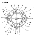
- Fig. 1 to 5 is a section of a accumulation roller conveyor 1 in different views and a roller assembly shown.
- the accumulation roller conveyor 1 consists of a support frame 2 with two in the conveying direction - according to arrow 3 - extending and the accumulation roller conveyor 1 laterally bounding side parts 4, over several in the conveying direction - Arranged according to arrow 3 - spaced from each other, not shown Cross beams are connected and thus kept at a distance.
- the side parts 4 are in Form formed by C-shaped sheet metal profiles, the web is aligned upright.
- the accumulation roller conveyor 1 is in the conveying direction - according to arrow 3 - in several consecutive divided conveyor zones 5a to 5d divided.
- Each conveyor zone 5a to 5d has one in the support frame 2, in particular in the side parts 4 in the conveying direction - according to arrow 3 - to each other spaced apart plurality of idle rollers 6 and at least one roller assembly 7 on.
- the roller assembly 7 comprises an endlessly revolving, belt-like drive member 8, e.g. Chain, belt, constantly driven drive roller 9, e.g. Sprocket, pulley, and a drivable and / or brakable conveyor roller 10.
- the drivable and / or brakable, hollow cylindrical conveyor roller 10 is provided with circumferential grooves provided, in which endless circulating drive elements, in particular belt 11, are guided, which revolve around the two adjacent conveyor rollers 10. These are about more belt 11 with further conveyor rollers 10 of the same conveyor zone 5a; 5b; 5c; 5d drive connected.
- a mechanical, in particular frictionally engaged acting clutch device 12 in particular a mechanically actuated friction clutch, e.g. Disc clutch, in particular dual or multi-surface clutch, or cone clutch, as shown in the following figures, arranged, which via at least one adjusting device 13 relative to each other adjustable coupling parts 14, 15, as this example are shown in FIG.
- each conveying zone 5 a to 5 d is at least one in the conveying direction. according to arrow 3 - from the conveyor zone 5a to the conveyor zone 5d transported piece goods 18, e.g. a loading aid, such as cardboard, pallet, box, etc. more captive, mechanical or optical Sensor 19, in particular one in the path of movement of the piece goods 18 protruding Switching flap or a photoelectric cell, e.g. Photocell, assigned.
- a loading aid such as cardboard, pallet, box, etc. more captive, mechanical or optical Sensor 19
- a photoelectric cell e.g. Photocell
- the adjusting device 13 has in the present embodiment, two on a roller axis 20 of the roller assembly 7 of each conveyor zone 5a to 5d pivotally mounted Gear lever 21, 22 and a sensor 19 of the respective conveying zone 5a; 5b; 5c; 5d with the first shift lever 21 connecting the first shift linkage 23 and a second shift lever 22 of the relevant conveyor zone 5a; 5b; 5c; 5d with the in the conveying direction - according to arrow 3 - upstream conveyor zone 5d; 5c; 5b; 5a connecting further shift linkage 24.
- the Shift linkage 23, 24 are connected to the pivotable switching flaps and each with the Switch levers 21, 22 hingedly connected.
- This process can be continued as desired along the accumulation roller conveyor 1.
- the roller arrangement 7 according to the invention is on the roller axis 20 held between the side parts 4 of the support frame 2, on the drive roller 9 and the drivable and / or braked conveyor roller 10 via bearings 29, 30, in particular ball bearings, are stored.
- the conveyor roller 10 consists of a cylindrical conveyor roller shell 31 with his Front ends arranged, provided with a roller axis 20 coaxial bore provided Fördenollenböden 32, in which the bearings 30 are held for the conveyor roller 10.
- the coupling parts 14, 15 over the two on the roller axis 20 pivotally mounted shift lever 21, 22 formed relative to each other adjustable.
- the drive roller 9 adjacent shift lever 21 has a cup-like receiving body 33 on the bottom of the cup with a hole for passing through the roller axis 20 is provided.
- the other the side part 4 adjacent shift lever 22 is over the at least two fan discs 25, 26 supported on the shift lever 21.
- Each of the two fan disks 25; 26 is preferably immovable with one of the shift levers 21, 22 connected. In the present embodiment is with the on the roller axis 20 pivotally mounted shift lever 22, the fan disk 25 and lever 21 the Fan disc 26 connected.
- the fan disk 25 has at least two, preferably four Control cam 34, which are arranged in the circumferential direction equidistant from each other are and opposing wedge ramps in axially recessed, parallel stop surfaces pass.
- Fan disk 26 is formed with complementary to the fan disk 25 switching cam 35, Wedge ramps and stop surfaces provided.
- first coupling part 14 is on the roller axis 20 slidably mounted, displaceable in the axial direction and the switching force the adjusting device 13 transmitting, hollow cylindrical or tubular switching element 27, which is designed in the manner of a collar sleeve arranged.
- a radially encircling collar 38 is formed between the and the end face on the pipe section of the shift lever 21 is pivotally mounted.
- a coaxial arranged on the roller axle 20 arranged support plate 39 is a coaxial arranged on the roller axle 20 arranged support plate 39.
- a hollow cylindrical plain bearing bush 40 is arranged over Circlips 41 and the bearing 29 relative to the axially adjustable switching element 27 and the drive roller 9 is axially fixed.
- the first coaxial with the roller axis 20 Coupling member 14 is integrally formed on this, to be described in more detail rotationally symmetrical first transmission element 42 and in the direction of the drive roller 9 tapered coupling surface 43 on.
- the other complementary to the first coupling part 14 formed, further coupling part 15 is connected by a on one of the conveyor roller 10th facing recessed recess with a in the direction of the conveyor roller 10 conically widening coupling surface 44 is formed.
- An opening angle 45 dimensioned between the coupling surfaces 43; 44 is between 5 ° and 50 °, for example 30 °.
- At least one adjusting device 47 is arranged, which in the present embodiment is formed such that at least the first transmission element 42 coaxially connected within a movement with the drivable and braked conveyor roller 10, arranged rotationally symmetric further transmission element 48 and with this rotatably via a toothing 49 in the circumferential direction of the transmission elements 42, 48 and in the axial direction to the roller axis 20 against each other are displaced.
- this is in the manner of a helix relative to the further transmission element 48 adjustable, first transmission element 42 through a cylindrical base body 50 with a coaxial with the roller axis 20th extending through hole 51 formed and bounded by two end faces 53, 54.
- One Outer circumference 52 of the first transmission element 42, preferably the outer circumference 52 of the Main body 50 is provided with an external toothing with at least two, preferably four in the circumferential direction provided at the same distance from each other toothed elements 55a.
- the toothed elements 55 a point in the direction of a longitudinal center axis 56 of the roller axis 20 or a longitudinal central axis 57 of the first transmission element 42 inclined to each other tapered and inclined to the longitudinal central axis 56, 57 extending wedge edges 58 or, as in 8 in dotted lines, in the direction of the longitudinal central axis 56 of Roller axis 20 and the longitudinal center axis 57 of the first transmission element 42 in parallel to each other and inclined to the longitudinal central axis 56, 57 of the wedge flanks 58 running on.
- pot-shaped further transmission element 48 is by a hollow cylindrical base body 59 with an internal toothing with tooth elements 55b and a arranged on these at one of its end faces 60, 61 bottom 62 formed.
- the bottom 62 has a coaxial with the roller axis 20 extending bore 63 for a bearing receiving point for the bearing 30 of the conveyor roller 10 and are on an inner periphery 64th the hollow cylindrical body 59 in the circumferential direction of the further transmission element 48 arranged at the same distance from each other, complementary to the tooth elements 55a formed, twisted longitudinal grooves 65 recessed.
- the radially outward directed in the direction of the conveyor roller 10 and circumferentially by the tooth elements 55b limited longitudinal grooves 65 have, as shown in FIGS.
- the wedge flanks 66 of the longitudinal grooves 65 correspond to the wedge edges 58 of the tooth elements 55b.
- the wedge flanks 66 are parallel to each other and inclined to the longitudinal central axis 56 of the roller axle 20 extending formed. However, this is not shown further.
- the wedge edges 58, 66 close to the longitudinal center axis 56, 57 of the roller axle 20 and the transmission element 42, 48 an angle 67 greater than 0 °, in particular between 5 ° and 50 °, for example 10 °, 20 °, 30 °.
- the first transmission element 42 is at the further transmission element 48 facing End face 54 with a part of a length 68 extending, circular cylindrical Recess 69 provided, and is between the first transmission element 42nd and the further transmission element 48 inserted in the recess 69, the at least a spring element 36, in particular a compression spring, aligned in the direction of the roller axis 20.
- a spring element 36 in particular a compression spring
- the first coupling part 14 may also be facing on its drive roller 9 Front side 70 a coaxial with the roller axis 20 formed recess 71, as in dashed lines in Fig. 8 registered, have for receiving the support plate 39.
- a preferred embodiment also provides the arrangement of a braking device 72nd between the movably connected to the displaceable first coupling part 14, first transmission element 42 and the roller axle 20.
- the first transmission element 42 forms a coaxial with the roller axis 20 in the region of the recess 69 Brake extension 73 of which, with a stuck on the roller axle 20, coaxial with the roller axis 20 circumferential brake pad 74 is engageable, wherein the brake extension 73 and the brake pad 74 are each provided with conical braking surfaces 75.
- the switching position, where the first coupling part 14 is in its engaged switching position and the braking device 72 is not actuated is apparent from Fig. 3 and the switching position, where the first coupling part 14th is in its disengaged switching position and the braking device 72 is actuated is off of Fig. 5 can be seen.
- the brake extension 73 at the same time as a guide in the radial direction for the at least one spring element 36 are used.
- the brake pad 72 may be connected to the roller axle 20 manufactured in one piece or as a separate component on this example. over a shrinkage or adhesive or welded joint, etc. are attached.
- the first coupling part 14 and the first transmission element 42 and the braking device 72 may be made in one piece from plastic, in particular thermoplastic, duroplastic, e.g. glass fiber reinforced Polyamide having a glass content of preferably 25%, polycarbonate, e.g. in the Injection molding process, fiber spraying process, extrusion process can be produced.
- plastic in particular thermoplastic, duroplastic, e.g. glass fiber reinforced Polyamide having a glass content of preferably 25%, polycarbonate, e.g. in the Injection molding process, fiber spraying process, extrusion process can be produced.
- Another Embodiment is that the first transmission element 42 made of steel and the first Coupling member 14 by a in the region of the drive roller 9 facing end 53rd glued friction lining with conical coupling surface 43 is formed.
- the further transmission element 48 is also made of plastic, in particular in the illustrated embodiment Thermoplastic, e.g. glass fiber reinforced polyamide with a glass content of preferably 25%, Polycarbonate etc., formed
- the axial force - according to arrow 80 - is functionally dependent on the weight of the transported Good quality 18. The higher the weight of the piece goods 18, the greater the axial force - According to arrow 80 - and thus the contact pressure between the two coupling parts 14, 15th
- the counter to the axial force - according to arrow 80 - acting switching force - according to arrow 79 - must for the disengagement of the coupling device 12 are applied only briefly, because as soon as the wedge flanks 58 are disengaged, the axial force - according to arrow 80 - repealed.
- a covering length 81 corresponds to the type a helix in one another guided, relatively adjustable transmission elements 42, 48 at least a double, preferably a multiple of an axial displacement path of one of the other coupling part 15 in drive connection standing engaged switching position in a disengaged switch position adjustable first coupling part 14th
- Fig. 6 shows the disengaged switching position of the coupling device 12.
- the wedge flanks 58, 66 inclined with respect to the longitudinal central axis 56 also have an effect because, during the displacement of the first coupling part 14 in the direction of the rotating Conveyor roller 10 is a braking force - according to arrow 82 - is generated and the conveyor roller 10 already even before the mutual engagement of the brake extension 73 and brake pad 74 at least can be slightly slowed down.
- Fig. 10 another embodiment of the adjusting device 47 is shown, consisting from the via the teeth 49 engaged with each other and in to the roller axis 20 axial direction and circumferential direction mutually adjustable, mechanical transmission elements 42, 48.
- the first transmission element 42 is characterized by a cylindrical Base 50 formed with the coaxial with the roller axis 20 extending through hole 51 and bounded by the two end faces 53, 54.
- On the outer circumference 52 is the main body 50 with at least two, preferably four in the circumferential direction equidistant from each other arranged toothed elements 55 a provided in the inner periphery of the other Transmission element 48 recessed arranged and circumferentially limited longitudinal grooves 65 are guided.
- the further transmission element 48 is cup-shaped and has already been described in detail above.
- the at least one spring element 36 in particular the compression spring, centric to the roller axis 20 arranged. Is a piece goods 18 with a weight exceeding the minimum weight is transported between the coupling part 14 and the first transmission element 42 dimensioned in the direction of the roller axis 20 distance 83 through which moving in the direction of the first coupling part 14 in the manner of a helix reduced first transmission element 42 and with the reduction of this distance 83rd the spring force according to - arrow 76 - and the contact pressure of the first coupling part 14 via the spring force increases against the further coupling part 15.
- first coupling member 14 As in this figure further registered, which is slidable on the roller axle 20 first coupling member 14 with a parallel to the longitudinal central axis 56 and roller axis 20 extending external teeth 84a and the conveyor roller 10 or connected to this immovable socket with a parallel to the longitudinal central axis 56 and roller axis 20 extending, complementary internal teeth 84b provided, which are engaged with each other and in the engaged switching position the first coupling part 14, the torque from the drive roller 9 via the first coupling part 14 and the outer and inner teeth 84 a, 84 b on the conveyor roller 10 is transmitted.
- the coupling part 14 is therefore by means of the external and internal teeth 84 a, 84 b rotatably connected to the conveyor roller 10 and against these slidably connected.
- the at least one braking device 72 are arranged between the conveyor roller 10 and the displaceable first coupling part 14, the at least one braking device 72 are arranged.
- the Brake extension 73 is connected to the first coupling part 14 on a transmission element 42nd facing end face and the brake pad 74 with the conveyor roller 10 on its inner circumferential surface firmly connected and are the complementarily formed braking surfaces 75 of the brake extension 73 and the brake pad 74 in the disengaged switching position of the coupling device 12 in frictional engagement with each other. This is not shown further.
- FIGS. 11 to 13 is a further embodiment of the Actuator 47 shown in different views and greatly simplified.
- the each other engaged transmission elements 42, 48 form at their facing each other End sides 54, 61 in each case at least two, preferably four in the circumferential direction with the same distance from each other, oppositely directed towards each other axially Tooth elements 55a, 55b, starting from a stop web with parallel to a radial plane - RE - extending stop surfaces 85 in the direction of rotation - according to arrow 77 - have rising wedge edges 58.
- the rising wedge edge 58 concludes the radial plane - RE - the angle 67 greater than 0 °, in particular between 5 ° and 50 °, for example 30 °.
- the first transmission element 42 comprising at least one spring element 36 arranged coaxially with the roller axis 20.
- the Gearing 49 respectively on the mutually facing end faces 54, 61 of the transmission elements 42, 48 integrally formed.
- the first transmission element 42 is in the present Embodiment formed of steel and is on a in the range of the drive roller. 9 facing the end face of the transmission element 42 a paragraph for glued on this Reibbelag 86 formed.
- the further transmission element 48 is preferably made Plastic.
- FIG. 14 to 16 is a further embodiment of the invention Roller assembly 7 with a support frame 2 of the accumulation roller conveyor arranged fixed roller axle 20 on which the drive roller 9 and the driving and optionally brakeable conveyor roller 10 is rotatably mounted, partially cut and strong shown in simplified form.
- Between the drive roller 9 and the drivable and / or braked Conveyor roller 10 is at least one mechanical coupling device 12 with over the adjustment 13, in particular the shift lever 21 relative to each other adjustable coupling parts 87, 88, 89 arranged.
- the first coupling part 87 is formed by a section of the drivable and optionally brakable, hollow cylindrical conveyor roller 10 with a for Longitudinal axis 56 of the roller axis 20 concentric coupling surface 90, the second Coupling member 88 through a portion of the drive roller 9 and between the first and the second coupling part 87, 88 arranged third coupling part 89 by a hollow cylindrical Overdrive roller 91 is formed.
- the overdrive roller 91 is within the drive and conveyor roller 9, 10 are arranged.
- the second coupling part 88 is by a coaxial with the roller axis 20 formed recess 92 with a concentric about the longitudinal central axis 56 of the roller axis 20 rotating clutch surface 93 provided.
- a section of an inner The lateral surface of the conveyor roller 10 forms the coupling surface 90 and an outer circumferential surface the overdrive roller 91 forms one with the coupling surfaces 90, 93 of the conveyor roller 10th and drive roller 9 engageable clutch surfaces 94.
- the overdrive roller 91 is via the shift lever 21 relative to the conveyor roller 10 and roller axle 20 of a disengaged Switching position, as shown in FIG. 15, in one with the first coupling part 87th and the second coupling part 88 with the coupling surfaces 90, 93 in drive connection standing, engaged switching position, as shown in FIG. 16, pivotable - according to Registered double arrow 95 - trained.
- the hollow cylindrical, roller-like overdrive roller 91 is on one, opposite an eccentric bushing 96 held on the roller axle 20 pivotable in the circumferential direction or in the radial plane swivel sleeve 97 rotatable stored.
- the pivot bushing 97 is rotatable with the in a bore 98 in the roller axis 20 mounted and a switching force of the adjusting device 13 transmitting, rod-shaped Switching element 27 connected.
- a pivot angle 99 between 10 ° and 30 °, in particular between 15 ° and 25 °, for example 17 °, rotatable switching element 27 to an electric or pneumatic or to couple hydraulic rotary actuator.
- the sensors 19 of the Stollen roller conveyor 1 by non-contact piece goods detecting sensors 19, e.g. photoelectric Cells are formed and receive the each roller assembly 7 associated with rotary actuators the conveyor zones 5a; 5b; 5c; 5d an electrical control signal.
- the pivot bushing 97 is at their opposite end faces 100 in this recessed arranged driving slots 101, in which with the bolt-shaped switching element 27 immovably connected actuators, in particular cylindrical pins 102nd against rotation of the pivot bushing 97 are positioned and positioned over the a pivoting movement from the shift lever 21 via the switching element 27 and the pivot bushing 97 is transmitted to the rotatably mounted on this Mattertriebsrolle 91.
- the shifter 21 of the adjusting device 13 is also connected to the switching element 27 via a cylindrical pin 102 immovably connected.
- the bearing 103 in particular rolling bearings, supported on the pivot bush 97, rotatable Overdrive roller 91 is in the direction of its length 104 in two coupling sections 105a, Divided 105b, wherein a first coupling portion 105a in the engaged switching position with its coupling surface 94 with a portion of the circumference of the coupling surface 93 of the drive roller 9 and the further coupling portion 105b with its coupling surface 94 with a portion of the circumference of the coupling surface 90 of the driving and optionally brakeable conveyor roller 10 is in frictional engagement.
- the torque be transmitted from the drive rollers 9 on the overdrive roller 91 on the conveyor roller 10.
- the eccentric bush 96 is at its in the direction of Roll axis 20 facing away from end faces with recessed, diametrically opposite, radially directed and circumferentially limited, slot-like receiving areas 106 and the roller shaft 20 with penetrated by the cylindrical pins 102 cylindrical openings 107 provided.
- the friction lining 86 on an outer and / or inner circumferential surface of the Mattertriebsrolle 91 or drive and conveyor roller 9, 10 ensures a slip-free transmission the torque from the drive rollers 9 on the conveyor roller 10th
- the conveyor roller 10 in the region of the coupling surface 90 forming subsection and / or the Kochtriebsrolle 91 in the area of the Coupling surface 94 forming coupling part sections 105a, 105b at least one in radial Direction has at least slightly elastic compliant layer of plastic. This layer is covered by the friction lining 86 and, for example, by polyurethane a Shore hardness of 80 formed.
- the overlapping length 81 of the coupling surface 94 of the coupling part sections 105a, 105b and the coupling surface 90, 93 of the conveying and driving roller 9, 10 is in the vertical to the longitudinal central axis 56 extending radial plane between 10 ° and 45 °, in particular between 20 ° and 30 °, for example 25 °, and in parallel to the roller axis 20 direction about half of the length 104 of the overdrive 91.
- the length 104th and / or the elasticity of the material of the coating 86 and / or the pressing force of the overdrive roller 91 against the first and second coupling part 87, 88 vary.
- the length 104 can be between 10 mm and 120 mm, in particular between 20 mm and 60 mm, for example 50 mm.
- An outer diameter of the third coupling part 89 and the Clutch surface 94 of the coupling part sections 105a, 105b is at least slightly smaller dimensioned as an inner diameter of the first and second coupling part 87, 88 and the Clutch surfaces 90, 93.
- a disc-like brake extension 73 with eccentric to the longitudinal central axis 56 extending braking surface 75 immovably connected.
- the conveyor roller 10 forms with her inner lateral surface in addition to the coupling surface 90 with the first braking surface 75th of the brake extension 73 engageable further braking surface 75 from.
- the brake extension 73 is pivoted and the first braking surface 75 of the brake extension 73 against the further braking surface 75 of the conveyor roller 10 with a predeterminable Braking force pressed or the braking surfaces 75 engage each other and the conveyor roller 10 is braked.
- the approximately disc-like brake extension 73 is made of a wear resistant and high friction plastic, e.g. from a thermoplastic, Duroplast, formed.
- FIG. 17 to 19 is a further embodiment of the invention Roller assembly 7 for a accumulation roller conveyor, not shown in this figure 1, partially cut and shown greatly simplified.
- the roller assembly 7 has the fixed in the side parts 4 of the support frame 2 roller axle 20 with the on her stored drive roller 9 and the drivable conveyor roller 10. Between the drive roller 9 and the conveyor roller 10 is the on the adjusting device 13, in particular the shift lever 21 relative to each other adjustable coupling parts 87, 88, 89 having coupling device 12 arranged.
- the first coupling part 87 is formed by a section of the conveying roller 10, the second coupling part 88 by a drivingly connected to the drive roller 9, hollow cylindrical Driving roller 108 and between the first and second coupling part 87, 88th arranged third coupling part 89 by a circular cylindrical, roller-like Mattertriebsrolle 91 formed.
- the driving roller 108 in the embodiment shown in these figures in one of the drive roller 9 facing end portion with an external toothing 109 and the drive roller 9 in the region of its recess 92 with a coaxial with the roller axis 20th arranged internal teeth 110 equipped. Between the outer and inner teeth 109, 110 of the drive roller 108 and the drive roller 9 is an intermediate gear 111 and gear arranged.
- the intermediate gear 111 is rotatably mounted on a fixed axle 112, which in turn is attached to a stationary retaining flange 113.
- the drive roller 108 is therefore constantly driven and rotated on the roller shaft 20 at a predetermined speed in the direction of rotation - according to arrow 77.
- the roller-like overdrive roller 91 is pivotable about the roller axis 20 Adjusting lever 114 is mounted, with the rotatably mounted in the bore 98 and the switching force the adjusting device 13, in particular of the shift lever 21 transmitting, rod-shaped Switching element 27 is connected.
- a the pivot angle 99 of the shift lever 21 corresponding pivot angle 115 of Oversizing roller 91 is between 10 ° and 30 °, in particular between 15 ° and 25 °, for example 17 °.
- the drive roller 108 is on the roller axis 20 via the bearings 103, in particular rolling bearings rotatably mounted.
- the overdrive roller 91 is made of plastic, e.g. a thermoset, thermoplastic, formed.
- plastic e.g. a thermoset, thermoplastic
- the Conveyor roller base 32 is cup-shaped and forms with its from a base protruding hollow cylinder-like wall 116, the coupling surface 90 for the Sprintmansrolle 91 off.
- the first coupling part 87 also by a portion of the inner circumferential surface of the conveying roller 10, the coupling surface 90 form.
- the conveyor roller floor 32 may be made of plastic or metal and is immovable with the conveyor roller 10, e.g. connected via grooved pins, dowel pins, glue.
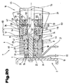
- FIG. 20 shows a further embodiment of the roller arrangement 7 according to the invention partially cut and shown in a highly simplified schematic representation.
- These Roller assembly 7 has on the support frame 2 arranged in the fixed roller shaft 20th the rotatably mounted and driven drive roller 9 and the at least drivable over the bearings 30 on the roller shaft 20 rotatably mounted conveyor roller 10.
- the coupling device 12 consists of the about the adjusting device 13, in particular the shift lever 21, 22 relative to each other adjustable Clutch parts 14, 15.
- the first coupling part 14 is on the roller axis 20 of the engaged switch position in the disengaged switch position against the at least a spring element 36 arranged axially adjustable.
- the adjusting device 47 has at least two via the teeth 49 with each other engaged and in the roller axis 20 axial direction against each other adjustable mechanical transmission elements 117, 118 and a fixed third transmission elements 119 on.
- the rotationally symmetrical second transmission element 117 forms a hollow cylindrical body and one of this radially outwardly projecting, circumferential Flange 120, in which arranged to the roller axis 20 coaxial passage opening 51 is.
- the second transmission element 117 is at its inner periphery 64 with a parallel to Roll axis 20 extending inner teeth 121 and provided on the, a ring land 122 with a complementary and parallel to the roller axis 20 extending external teeth 123 forming the first coupling part 14 is arranged axially displaceable.
- the at least one spring element 36 is between the first coupling part 14 and a second transmission element 117 is arranged.
- a third transmission element 119 is disk-shaped formed and with the roller axis 20 coaxial bore 63 for the bearing 30th provided the conveyor roller 10 and immovably connected to the conveyor roller 10.
- the second Transmission element 117 is between the first and third transmission element 118, 119th arranged.
- the first and second transmission members 118, 117 are to the third transmission element 119 and relative to each other, in particular axially, adjustable.
- the adjacent transmission elements 117, 119 are at their facing each other End faces 54, 61 with recessed arranged in these, radially encircling and in the radial direction -
- slide tracks 125 provided between which arranged in the radial direction - as shown by arrow 124 - spherical sliding blocks 126 are.
- the slide tracks 125 have a circular arc, in each case the end faces 54, 61 facing a convex course.
- the first coupling part 14 is with the minimum weight of a to be transported Good 18 designed spring force corresponding pressure force against the other Clutch part 15 pressed.
- the first coupling part 14 is exclusive with the pressure force proportional to the spring force against the further coupling part 15 pressed.
- the accumulation roller conveyor 1 for in this in each conveyor zone 5a, 5b, 5c, 5d inserted roller assembly 7 of FIGS. 14 to 19 in shown different views.
- the accumulation roller conveyor 1 consists of the support frame. 2 with the in the conveying direction - according to arrow 3 - extending and the accumulation roller conveyor 1 side bordering side parts 4, over several in the conveying direction - as shown by arrow 3 - seen spaced apart, not shown cross members are connected and thus kept at a distance.
- the accumulation roller conveyor 1 is in the conveying direction according to - Arrow 3 - divided into several consecutively formed conveying zones 5a to 5d. Every conveyor zone 5a to 5d has the support frame 2, in particular in the side parts 4 in the conveying direction - According to arrow 3 - spaced from each arranged variety of undriven Rollers 6 and the at least one roller assembly 7 according to FIGS. 14 to 19.
- each conveying zone 5 a to 5 d is at least one in the conveying direction.
- a loading aid such as cardboard, pallet, box, etc.
- detecting sensor 19 in particular a in the path of movement of the piece goods 18 projecting switching flap or a photoelectric Cell, e.g. Photocell, assigned.
- the adjusting device 13 has in the present embodiment, two on a roller axis 20 of the roller assembly 7 of each conveyor zone 5a to 5d pivotally mounted Gear lever 21, 22 and a sensor 19 of the respective conveying zone 5a; 5b; 5c; 5d with the first shift lever 21 connecting the first shift linkage 23 and a second shift lever 22 of the relevant conveyor zone 5a; 5b; 5c; 5d with the in the conveying direction - according to arrow 3 - upstream conveyor zone 5d; 5c; 5b; 5a connecting further shift linkage 24.
- the Shift linkage 23, 24 are connected to the pivotable switching flaps and each with the Switch levers 21, 22 hingedly connected.
- the adjusting device 13 has in the present embodiment on the Roller axis 20 of the roller assembly 7 of each conveyor zone 5a to 5d pivotally mounted Shift lever 21 and the sensor 19 with the relevant conveyor zone 5a; 5b; 5c; 5d connected to the shift lever 21 first shift linkage 23.
- first transmission element 42; 117 and / or the further transmission element 48; 118 and / or the first coupling part 14 or at least one Part of the same made of metal and / or plastic e.g. Thermoplastic, thermoset, e.g. glass fiber reinforced Polyamide having a glass content of preferably 25%, polycarbonate, etc. formed are.
- FIGS. 1 to 9; 10; 11, 12, 13; 14, 15, 16; 17, 18, 19; 20; 21, 22 shown the subject of independent, inventive Form solutions.
- the relevant objects and solutions according to the invention are the Detailed descriptions of these figures can be seen.
Landscapes
- Engineering & Computer Science (AREA)
- Mechanical Engineering (AREA)
- Rollers For Roller Conveyors For Transfer (AREA)
Description
- Fig. 1
- schematisch einen Ausschnitt eines erfindungsgemäße Staurollenförderers, in Seitenansicht;
- Fig. 2
- den Staurollenförderer nach Fig. 1 in Draufsicht und in stark vereinfachter, schematischer Darstellung;
- Fig. 3
- eine erfindungsgemäße Rollenanordnung einer Förderzone des Staurollenförderers, mit der Antriebsrolle und Förderrolle und einer zwischen diesen angeordneten Kupplungseinrichtung in eingerückter Schaltstellung, geschnitten gemäß den Linien III-III in Fig. 2 und in stark vereinfachter, schematischer Darstellung;
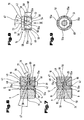
- Fig. 4
- eine Förderrolle und eine Stellvorrichtung mit sich in Eingriff befindlichen Übertragungselementen, geschnitten gemäß den Linien IV - IV in Fig. 3;
- Fig. 5
- die Rollenanordnung nach Fig. 3 mit der Kupplungseinrichtung in ausgerückter Schaltstellung, im Längsschnitt und stark vereinfachter schematischer Darstellung;
- Fig. 6
- eine schematisch dargestellte Antriebsrolle und einen Teilbereich der Förderrolle und die zwischen diesen angeordnete Kupplungseinrichtung in eingerückter Schaltstellung, sowie die zwischen der Kupplungseinrichtung, insbesondere dem ersten Kupplungsteil und der Förderrolle angeordnete Stellvorrichtung , im Längsschnitt und in stark vereinfachter, schematischer Darstellung;
- Fig. 7
- eine schematisch dargestellte Antriebsrolle und einen Teilbereich der Förderrolle und die zwischen diesen angeordnete Kupplungseinrichtung in ausgerückter Schaltstellung sowie die zwischen der Kupplungseinrichtung, insbesondere dem ersten Kupplungsteil und der Förderrolle angeordnete Stellvorrichtung , im Längsschnitt und in stark vereinfachter, schematischer Darstellung;
- Fig. 8
- das erfindungsgemäße erste Übertragungselement mit dem ersten Kupplungsteil in Ansicht und in stark vereinfachter, schematischer Darstellung;
- Fig. 9
- das Übertragungselement mit dem Kupplungsteil in Ansicht gemäß Pfeil IX in Fig. 8;
- Fig. 10
- eine andere Ausgestaltung der erfindungsgemäßen Rollenanordnung und eine weitere Ausführung der Stellvorrichtung mit ihren sich miteinander in Eingriff befindlichen Übertragungselementen und die Kupplungseinrichtung, teilweise geschnitten und in stark vereinfachter, schematischer Darstellung;
- Fig. 11
- eine weitere Ausführungsvariante der erfindungsgemäßen Rollenanordnung mit einer anderen Ausführung der Stellvorrichtung mit ihren sich miteinander in Eingriff befindlichen Übertragungselementen und die Kupplungseinrichtung, im Längsschnitt und in stark vereinfachter, schematischer Darstellung;
- Fig. 12
- das erste Übertragungselement mit dem mit diesem verbundenen ersten Kupplungsteil, in Stirnansicht und in stark vereinfachter, schematischer Darstellung;
- Fig. 13
- eine Ansicht in Richtung der Pfeile XIII - XIII in Fig. 12 eines Teils einer Verzahnung des Übertragungselementes, in stark vereinfachter und schematischer Darstellung;
- Fig. 14
- eine andere Ausgestaltung der erfindungsgemäßen Rollenanordnung mit einer sich in ausgerückter Schaltstellung befindlichen Kupplungseinrichtung, geschnitten gemäß den Linien XIV -XIV in Fig. 22 und in stark vereinfachter, schematischer Darstellung;
- Fig. 15
- die Kupplungseinrichtung in ausgerückter Schaltstellung und die Förderrolle, nach Fig. 14, in Stirnansicht, teilweise geschnitten und in stark vereinfachter, schematischer Darstellung;
- Fig. 16
- die Kupplungseinrichtung in eingerückter Schaltstellung und die Förderrolle, nach Fig. 14, in Stirnansicht, teilweise geschnitten und in stark vereinfachter, schematischer Darstellung;
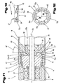
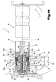
- Fig. 17
- eine weitere Ausführungsvariante der erfindungsgemäßen Rollenanordnung im Längsschnitt und in stark vereinfachter, schematischer Darstellung;
- Fig. 18
- die Kupplungseinrichtung in ausgerückter Schaltstellung, eine Treibrolle und die Förderrolle, geschnitten gemäß den Linien XVIII - XVIII in Fig. 17, in stark vereinfachter, schematischer Darstellung;
- Fig. 19
- die Kupplungseinrichtung in eingerückte Schaltstellung, die Treibrolle und die Förderrolle, nach Fig. 17, in Stirnansicht geschnitten, und in stark vereinfachter schematischer-Darstellung;
- Fig. 20
- einen Ausschnitt einer anderen Ausgestaltung der erfindungsgemäßen Rollenanordnung mit einer weiteren Ausführungsvariante der Stellvorrichtung, im Längsschnitt und in stark vereinfachter, schematischer Darstellung;
- Fig. 21
- schematisch einen Ausschnitt einer weiteren Ausführung eines erfindungsgemäßen Staurollenförderers für die Rollenanordnung nach den Fig. 14 bis 19, in Seitenansicht;
- Fig. 22
- den Staurollenförderer nach Fig. 21 in Draufsicht und in stark vereinfachter, schematischer Darstellung.
- 1
- Staurollenförderer
- 2
- Tragrahmen
- 3
- Pfeil
- 4
- Seitenteil
- 5a
- Förderzone
- 5b
- Förderzone
- 5c
- Förderzone
- 5d
- Förderzone
- 6
- Rolle
- 7
- Rollenanordnung
- 8
- Antriebsorgan
- 9
- Antriebsrolle
- 10
- Förderrolle
- 11
- Riemen
- 12
- Kupplungseinrichtung
- 13
- Verstellvorrichtung
- 14
- Kupplungsteil
- 15
- Kupplungsteil
- 16
- Andrückrolle
- 18
- Stückgut
- 19
- Sensor
- 20
- Rollenachse
- 21
- Schalthebel
- 22
- Schalthebel
- 23
- Schaltgestänge
- 24
- Schaltgestänge
- 25
- Fächerscheibe
- 26
- Fächerscheibe
- 27
- Schaltelement
- 29
- Lager
- 30
- Lager
- 31
- Förderrollenmantel
- 32
- Förderrollenboden
- 33
- Aufnahmekörper
- 34
- Schaltnocke
- 35
- Schaltnocke
- 36
- Federelement
- 38
- Bund
- 39
- Stützscheibe
- 40
- Gleitlagerbuchse
- 41
- Sicherungsring
- 42
- Übertragungselement
- 43
- Kupplungsfläche
- 44
- Kupplungsfläche
- 45
- Öffnungswinkel
- 47
- Stellvorrichtung
- 48
- Übertragungselement
- 49
- Verzahnung
- 50
- Grundkörper
- 51
- Durchgangsöffnung
- 52
- Außenumfang
- 53
- Stirnseite
- 54
- Stirnseite
- 55a
- Zahnelement
- 55b
- Zahnelement
- 56
- Längsmittelachse
- 57
- Längsmittelachse
- 58
- Keilflanke
- 59
- Grundkörper
- 60
- Stirnseite
- 61
- Stirnseite
- 62
- Boden
- 63
- Bohrung
- 64
- Innenumfang
- 65
- Längsnut
- 66
- Keilflanke
- 67
- Winkel
- 68
- Länge
- 69
- Ausnehmung
- 70
- Stirnseite
- 71
- Aussparung
- 72
- Bremseinrichtung
- 73
- Bremsfortsatz
- 74
- Bremsklotz
- 75
- Bremsfläche
- 76
- Federkraft
- 77
- Rotationsrichtung
- 78
- Kraftkomponente
- 79
- Schaltkraft
- 80
- Axialkraft
- 81
- Überdeckungslänge
- 82
- Bremskraft
- 83
- Abstand
- 84a
- Außenverzahnung
- 84b
- Innenverzahnung
- 85
- Anschlagfläche
- 86
- Reibbelag
- 87
- Kupplungsteil
- 88
- Kupplungsteil
- 89
- Kupplungsteil
- 90
- Kupplungsfläche
- 91
- Übertriebsrolle
- 92
- Ausnehmung
- 93
- Kupplungsfläche
- 94
- Kupplungsfläche
- 95
- Doppelpfeil
- 96
- Exzenterbuchse
- 97
- Schwenkbuchse
- 98
- Bohrung
- 99
- Schwenkwinkel
- 100
- Stirnfläche
- 101
- Mitnahmeschlitz
- 102
- Zylinderstift
- 103
- Lager
- 104
- Länge
- 105a
- Kupplungsteilabschnitt
- 105b
- Kupplungsteilabschnitt
- 106
- Aufnahmebereich
- 107
- Öffnung
- 108
- Treibrolle
- 109
- Außenverzahnung
- 110
- Innenverzahnung
- 111
- Zwischenrad
- 112
- Achse
- 113
- Halteflansch
- 114
- Stellhebel
- 115
- Schwenkwinkel
- 116
- Wandung
- 117
- Übertragungselement
- 118
- Übertragungselement
- 119
- Übertragungselement
- 120
- Flansch
- 121
- Innenverzahnung
- 122
- Ringsteg
- 123
- Außenverzahnung
- 124
- Radialrichtung
- 125
- Kulissenbahn
- 126
- Kulissenstein
- 127
- Käfig
- 128
- Grundstellung
- 129
- Betriebsstellung
Claims (34)
- Rollenanordnung (7) für das Fördern eines Stückgutes (18) entlang eines Staurollenförderers (1), mit einer in einem Tragrahmen (4) des Staurollenförderers (1) angeordneten feststehenden Rollenachse (20), auf der eine Antriebsrolle (9) und eine antreibbare und gegebenenfalls bremsbare Förderrolle (10) drehbar gelagert ist, sowie mit einer zwischen diesen angeordneten mechanisch betätigbaren Kupplungseinrichtung (12), insbesondere eine Reibkupplung, mit über eine Verstellvorrichtung (13) relativ zueinander verstellbaren Kupplungsteilen (14, 15), wobei zumindest einer der Kupplungsteile (14, 15) von einer eingerückten Schaltstellung in eine ausgerückte Schaltstellung entgegen der Wirkung von zumindest einem Federelement (36) auf der Rollenachse (20) axial verstellbar angeordnet und der erste Kupplungsteil (14) mit der Förderrolle (10) und der weitere Kupplungsteil (15) mit der Antriebsrolle (9) antriebsverbunden ist, und einander zugewandte Kupplungsflächen (43, 44) der Kupplungsteile (14, 15) in der eingerückten Schaltstellung mit einer Andruckkraft gegeneinander abgestützt sind, dadurch gekennzeichnet, dass zwischen der Förderrolle (10) und dem auf der Rollenachse (20) verstellbaren ersten Kupplungsteil (14) eine selbstnachstellende Stellvorrichtung (47) angeordnet ist, die zumindest zwei über eine Verzahnung (49) miteinander in Eingriff befindliche und in zur Rollenachse (20) axialer Richtung und/oder Umfangsrichtung gegeneinander verstellbare Übertragungselemente (42, 48; 117, 118) aufweist und dass der erste Kupplungsteil (14) bei einer Relativbewegung zwischen der Förderrolle (10) und dem ersten Kupplungsteil (14) in deren Umfangsrichtung in zur Rollenachse (20) axialer Richtung auf den weiteren Kupplungsteil (15) zu selbsttätig verstellt und die Kupplungsfläche (43) des ersten Kupplungsteiles (14) mit einer in Abhängigkeit vom Gewicht des von der Förderrolle (10) transportierten Stückgutes (18) eingestellten Andruckkraft gegen die Kupplungsfläche (44) des weiteren Kupplungsteiles (15) bis zum Erreichen eines schlupffreien Reibeingriffes zwischen den beiden Kupplungsteilen (14, 15) angepreßt wird.
- Rollenanordnung nach Anspruch 1, dadurch gekennzeichnet, dass das erste Übertragungselement (42; 118) mit dem ersten Kupplungsteil (14) und das zweite Übertragungselement (48; 117) mit der Förderrolle (10) gekoppelt bzw. bewegungsverbunden ist.
- Rollenanordnung nach Anspruch 1 oder 2, dadurch gekennzeichnet, dass die Stellvorrichtung (47) über eine Verzahnung (49) miteinander in Eingriff befindliche und in zur Rollenachse (20) axialer Richtung und Umfangsrichtung gegeneinander verstellbare, mechanische Übertragungselemente (42, 48) aufweist und dass Keilflanken (58) der Verzahnung (49) winkelig zur Rollenachse (20) oder zu einer zur Rollenachse (20) senkrechten Radialebene verlaufen.
- Rollenanordnung nach einem der Ansprüche 1 bis 3, dadurch gekennzeichnet, dass zumindest ein erstes Übertragungselement (42) koaxial innerhalb eines mit der antreib- und gegebenenfalls bremsbaren Förderrolle (10) bewegungsfest verbundenen, weiteren Übertragungselement (48) angeordnet und mit diesem über die Verzahnung (49) in Umfangsrichtung der Übertragungselemente (42, 48) und in zur Rollenachse (20) axialer Richtung gegeneinander verschiebbar verbunden sind.
- Rollenanordnung nach einem der Ansprüche 1 bis 4, dadurch gekennzeichnet, dass das erste Übertragungselement (42) durch einen zylindrischen Grundkörper (50) mit einer koaxial zur Rollenachse (20) verlaufenden Durchgangsöffnung (51) gebildet und von zwei Stirnseiten (53, 54) begrenzt ist und dass am Außenumfang (52) des Grundkörpers (50) zumindest zwei, bevorzugt vier in Umfangsrichtung mit gleichem Abstand voneinander angeordnete Zahnelemente (55a) angeordnet sind.
- Rollenanordnung nach einem der Ansprüche 1 bis 5, dadurch gekennzeichnet, dass das erste Übertragungselement (42) auf der Rollenachse (20) verschieb- und/oder verdrehbar gelagert und mit dem ersten Kupplungsteil (14) bewegungsfest verbunden, insbesondere einstückig mit diesem ausgebildet ist.
- Rollenanordnung nach einem der Ansprüche 1 bis 6, dadurch gekennzeichnet, dass der erste Kupplungsteil (14) auf der Rollenachse (20) axial verschiebbar gelagert und über eine Verzahnung (84a, 84b) mit der Förderrolle (10) drehfest verbunden ist und die miteinander in Eingriff befindlichen und in zur Rollenachse (20) axialer Richtung und Umfangsrichtung gegeneinander verstellbaren Übertragungselemente (42, 48) über das zumindest eine vorgespannte Federelement (36), insbesondere eine Druckfeder, gegen den ersten Kupplungsteil (14) abgestützt sind.
- Rollenanordnung nach einem der Ansprüche 1 bis 7, dadurch gekennzeichnet, dass die miteinander in Eingriff befindlichen Übertragungselemente (42, 48) an ihren einander zugewandten Stirnseiten (54, 61) mit jeweils wenigstens zwei, bevorzugt vier in Umfangsrichtung der Übertragungselemente (42, 48) mit gleichem Abstand voneinander angeordneten, gegensinnig axial aufeinander zugerichteten Zahnelementen (55a, 55b) versehen sind, die in Umfangsrichtung ansteigend verlaufende Keilflanken (58) aufweisen und dass zwischen den Übertragungselementen (42, 48) oder zwischen einem der Übertragungselemente (42; 48) und dem ersten Kupplungsteil (14) das zumindest eine vorgespannte Federelement (36) angeordnet ist.
- Rollenanordnung nach einem der Ansprüche 1 bis 8, dadurch gekennzeichnet, dass die Zahnelemente (55a) in Richtung der Rollenachse (20) die geneigt aufeinander und geneigt zu einer Längsmittelachse (56) der Rollenachse (20) verlaufenden Keilflanken (58) aufweisen.
- Rollenanordnung nach einem der Ansprüche 1 bis 8, dadurch gekennzeichnet, dass die Zahnelemente (55a) in Richtung der Rollenachse (20), die parallel zueinander und geneigt zur Längsmittelachse (56) der Rollenachse (20) verlaufenden Keilflanken (58) aufweisen.
- Rollenanordnung nach einem der Ansprüche 1 bis 10, dadurch gekennzeichnet, dass das weitere Übertragungselement (48) durch einen hohlzylindrischen Grundkörper (59) und gegebenenfalls einen an diesen an einer seiner Stirnseiten (60, 61) angeordneten Boden (62) gebildet ist und dass der Boden (62) eine koaxial zur Rollenachse (20) verlaufende Bohrung (63) aufweist und am Innenumfang (64) in Umfangsrichtung des Übertragungselementes (48) mit gleichem Abstand voneinander angeordnete, zu den Zahnelementen (55a) komplementär ausgebildete und umfangsmäßig begrenzte verdrallte Längsnuten (65) vertieft angeordnet sind.
- Rollenanordnung nach einem der Ansprüche 1 bis 11, dadurch gekennzeichnet, dass das weitere Übertragungselement (48) durch einen scheibenartigen Grundkörper (59) gebildet und in diesem eine koaxial zur Rollenachse (20) verlaufende Ausnehmung angeordnet ist, in der ein Lager (30) für die Förderrolle (10) eingesetzt ist und dass an der dem ersten Übertragungselement (42) zugewandten Stirnseite (61) die axial vorstehenden Zahnelemente (55b) ausgebildet sind.
- Rollenanordnung nach Anspruch 11, dadurch gekennzeichnet, dass die Längsnuten (65) in Richtung der Rollenachse (20) geneigt aufeinander und geneigt zur Längsmittelachse (56) der Rollenachse (20) verlaufende Keilflanken (66) aufweist.
- Rollenanordnung nach Anspruch 11, dadurch gekennzeichnet, dass die Längsnuten (65) in Richtung der Rollenachse (20) parallel zueinander und geneigt zur Längsmittelachse (56) der Rollenachse (20) verlaufende Keilflanken (66) aufweist.
- Rollenanordnung nach einem der Ansprüche 1 bis 14, dadurch gekennzeichnet, dass die Keilflanke (58, 66) mit der Längsmittelachse (56) oder der Radialebene einen Winkel (67) größer 0°, insbesondere zwischen 5° und 50°, beispielsweise 30°, einschließt.
- Rollenanordnung nach Anspruch 11, dadurch gekennzeichnet, dass eine Überdeckungslänge (81) der nach der Art einer Schraubenlinie ineinander geführten Übertragungselemente (42, 48) zumindest einem doppelten, bevorzugt einem mehrfachen eines axialen Verstellweges des von einer mit dem weiteren Kupplungsteil (15) in Antriebsverbindung stehenden, eingerückten Schaltstellung in eine ausgerückte Schaltstellung verstellbaren ersten Kupplungsteiles (14) entspricht.
- Rollenanordnung nach Anspruch 11 oder 12, dadurch gekennzeichnet, dass das weitere Übertragungselement (48) topfartig ausgebildet ist und am Boden (62) eine Lageraufnahmestelle für das Lager (30) der Förderrolle (10) ausbildet.
- Rollenanordnung nach einem der Ansprüche 1 bis 7, dadurch gekennzeichnet, dass das erste Übertragungselement (42) an der dem weiteren Übertragungselement (48) zugekehrten Stirnseite (54) eine koaxial zur Rollenachse (20) ausgebildete Ausnehmung (69) für die bereichsweise Aufnahme des Federelementes (36) aufweist.
- Rollenanordnung nach einem der Ansprüche 1 bis 18, dadurch gekennzeichnet, dass zwischen der Förderrolle (10) oder dem weiteren Übertragungselement (48) und dem auf der Rollenachse (20) verschiebbaren ersten Übertragungselement (42) und/oder dem ersten Kupplungsteil (14) eine Bremseinrichtung (72) angeordnet ist und dass die Bremseinrichtung (72) einen Bremsfortsatz (73) und einen Bremsklotz (74) aufweist.
- Rollenanordnung nach Anspruch 19, dadurch gekennzeichnet, dass das verschiebbare erste Übertragungselement (42) und/oder der erste Kupplungsteil (14) den Bremsfortsatz (73) aufweist, der mit dem auf der Rollenachse (20) und/oder an einer inneren Mantelfläche der Förderrolle (10) festsitzenden Bremsklotz (74) in Reibeingriff bringbar ist und dass der Bremsfortsatz (73) und der Bremsklotz (74) mit konischen Bremsflächen (75) versehen sind.
- Rollenanordnung nach Anspruch 19 oder 20, dadurch gekennzeichnet, dass der Bremsfortsatz (73) eine Führung für das zumindest eine Federelement (36) ausbildet.
- Rollenanordnung nach einem der Ansprüche 1 bis 19, dadurch gekennzeichnet, dass auf der Rollenachse (20) ein in axialer Richtung gleitbeweglich gelagertes und eine Schaltkraft der Verstellvorrichtung (13) übertragendes Schaltelement (27) angeordnet ist und dass das Schaltelement (27) gegen den ersten Kupplungsteil (14) abgestützt ist.
- Rollenanordnung nach einem der Ansprüche 1 bis 22, dadurch gekennzeichnet, dass der gegebenenfalls mit dem ersten Übertragungselement (42) einstückig verbundene, erste Kupplungsteil (14) eine sich in Richtung der Antriebsrolle (9) konisch verjüngende Kupplungsfläche (43) aufweist und dass ein Öffnungswinkel (45) zwischen 5° und 50°, beispielsweise 30°, beträgt.
- Rollenanordnung nach einem der Ansprüche 1 bis 23, dadurch gekennzeichnet, dass die Antriebsrolle (9) eine den weiteren Kupplungsteil (15) bildende Ausnehmung mit konischer Kupplungsfläche (44) aufweist und dass ein Öffnungswinkel (45) zwischen 5° und 50°, beispielsweise 30°, beträgt.
- Rollenanordnung nach einem der Ansprüche 1 bis 24, dadurch gekennzeichnet, dass die Stellvorrichtung (47) über eine Verzahnung (49) miteinander in Eingriff befindliche und in zur Rollenachse (20) axialer Richtung gegeneinander verstellbare, mechanische Übertragungselemente (117, 118) und ein koaxial zur Rollenachse (20) angeordnetes drittes Übertragungselement (119) aufweist und die einander benachbarten zweiten und dritten Übertragungselemente (117, 119) an ihren einander zugewandten Stirnseiten (54, 61) mit in diesen vertieft angeordneten, radial umlaufenden, im Querschnitt kreisbogenförmigen, jeweils der Stirnseite (54; 61) zugewandt konvex verlaufenden und in Radialrichtung der Übertragungselemente (117, 119) zueinander versetzten Kulissenbahnen (125) ausgebildet sind, zwischen denen in der Radialrichtung wenigstens ein verstellbarer Kulissenstein (126) angeordnet sind.
- Rollenanordnung nach Anspruch 25, dadurch gekennzeichnet, dass der erste Kupplungsteil (14) das erste Übertragungselement (118) ausbildet und einen Ringsteg (122) mit einer parallel zur Rollenachse (20) verlaufenden Außenverzahnung (123) aufweist und das zweite Übertragungselement (117) einen hohlzylindrischen Grundkörper mit einer parallel zur Rollenachse (20) verlaufenden Innenverzahnung (121) aufweist und dass das zweite Übertragungselement (117) auf dem ersten Übertragungselement (118) axial verschiebbar angeordnet ist.
- Rollenanordnung nach Anspruch 25 oder 26, dadurch gekennzeichnet, dass das zumindest eine Federelement (36) zwischen dem ersten Kupplungsteil (14) und zweiten Übertragungselement (117) vorgespannt angeordnet ist.
- Rollenanordnung (7) für einen Staurollenförderer (1), mit einer in einem Tragrahmen (2) des Staurollenförderers (1) angeordneten, feststehenden Rollenachse (20), auf der eine Antriebsrolle (9) und eine antreibbare und gegebenenfalls bremsbare Förderrolle (10) drehbar gelagert ist, sowie einer zwischen diesen angeordneten, mechanischen Kupplungseinrichtung (12) mit über eine Verstellvorrichtung (13) relativ zueinander verstellbaren Kupplungsteilen (87, 88, 89), dadurch gekennzeichnet, dass der erste Kupplungsteil (87) durch die Förderrolle (10) mit einer zur Längsmittelachse (56) der Rollenachse (20) konzentrischen Kupplungsfläche (90), der zweite Kupplungsteil (88) durch die Antriebsrolle (9) oder eine mit ihr antriebsverbundenen Treibrolle (108) und der zwischen dem ersten und zweiten Kupplungsteil (87,88) angeordnete dritte Kupplungsteil (89) durch eine Übertriebsrolle (91) gebildet ist und dass die von einer ausgerückten Schaltstellung in eine mit dem ersten Kupplungsteil (87) und den zweiten Kupplungsteil (88) mit Kupplungsflächen (90, 93) in Antriebsverbindung stehenden, eingerückten Schaltstellung verstellbare Übertriebsrolle (91) exzentrisch gelagert oder eine der Kupplungsflächen (90; 93) des ersten oder zweiten Kupplungsteiles (87; 88) exzentrisch zur Längsmittelachse (56) der Rollenachse (20) des ersten Kupplungsteiles (87) ausgebildet ist.
- Rollenanordnung nach Anspruch 28, dadurch gekennzeichnet, dass die walzenartige Übertriebsrolle (91) an einem um die Rollenachse (20) verschwenkbaren Stellhebel (114) gelagert ist, der mit einem in einer Bohrung (98) in der Rollenachse (20) drehbeweglich gelagerten und eine Schaltkraft der Verstellvorrichtung (13) übertragenden, stabförmigen Schaltelement (27) verbunden ist.
- Rollenanordnung nach Anspruch 28, dadurch gekennzeichnet, dass die hohlzylindrische, walzenartige Übertriebsrolle (91) auf einer Schwenkbuchse (97) drehbar gelagert ist und dass die Schwenkbuchse (97) auf einer an der Rollenachse (20) befestigten Exzenterbuchse (96) in deren Umfangsrichtung verstellbar, insbesondere gleitbeweglich auf der Exzenterbuchse (96) angeordnet und mit einem in einer Bohrung (98) in der Rollenachse (20) verdrehbeweglich gelagerten und eine Schaltkraft der Verstellvorrichtung (13) übertragenden, stabförmigen Schaltelement (27) verbunden ist.
- Rollenanordnung nach Anspruch 28 oder 30, dadurch gekennzeichnet, dass ein Außendurchmesser der Übertriebsrolle (91) geringfügig kleiner bemessen ist als ein Innendurchmesser der Antriebs- oder Förderrolle (9, 10).
- Rollenanordnung nach Anspruch 31, dadurch gekennzeichnet, dass die Antriebsrolle (9) eine den zweiten Kupplungsteil (88) bildende Ausnehmung (92) mit einer zur Längsmittelachse (56) der Rollenachse (20) konzentrischen Kupplungsfläche (93) aufweist.
- Rollenanordnung nach einem der Ansprüche 28 bis 32, dadurch gekennzeichnet, dass ein den Verstellweg der Übertriebsrolle (91) begrenzender und zwischen der eingerückten und ausgerückten Schaltstellung bemessener Schwenkwinkel (115) zwischen 10° und 30°, insbesondere zwischen 15° und 25°, beispielsweise 17°, beträgt.
- Staurollenförderer (1) mit einer Vielzahl von in einem Tragrahmen (2) gehaltenen Rollen (6, 9, 10), die mehreren Förderzonen (5a bis 5d) zugeordnet sind und in jeder Förderzone (5a bis 5d) eine Rollenanordnung (7) angeordnet ist, die mit den weiteren Rollen (6) derselben Förderzone (5a bis 5d) gekuppelt ist, dadurch gekennzeichnet, dass die Rollenanordnung (7) nach einem der Ansprüche 1 bis 33 ausgebildet ist.
Priority Applications (1)
| Application Number | Priority Date | Filing Date | Title |
|---|---|---|---|
| AT03735140T ATE309950T1 (de) | 2002-06-14 | 2003-06-06 | Rollenanordnung für einen staurollenförderer |
Applications Claiming Priority (3)
| Application Number | Priority Date | Filing Date | Title |
|---|---|---|---|
| AT9072002 | 2002-06-14 | ||
| AT0090702A AT413027B (de) | 2002-06-14 | 2002-06-14 | Rollenanordnung für einen staurollenförderer |
| PCT/AT2003/000166 WO2003106305A1 (de) | 2002-06-14 | 2003-06-06 | Rollenanordnung für einen staurollenförderer |
Publications (2)
| Publication Number | Publication Date |
|---|---|
| EP1517848A1 EP1517848A1 (de) | 2005-03-30 |
| EP1517848B1 true EP1517848B1 (de) | 2005-11-16 |
Family
ID=29721127
Family Applications (1)
| Application Number | Title | Priority Date | Filing Date |
|---|---|---|---|
| EP03735140A Expired - Lifetime EP1517848B1 (de) | 2002-06-14 | 2003-06-06 | Rollenanordnung für einen staurollenförderer |
Country Status (7)
| Country | Link |
|---|---|
| US (1) | US7290649B2 (de) |
| EP (1) | EP1517848B1 (de) |
| AT (1) | AT413027B (de) |
| AU (1) | AU2003237559A1 (de) |
| DE (1) | DE50301698D1 (de) |
| ES (1) | ES2253682T3 (de) |
| WO (1) | WO2003106305A1 (de) |
Cited By (3)
| Publication number | Priority date | Publication date | Assignee | Title |
|---|---|---|---|---|
| US7364035B2 (en) | 2005-05-25 | 2008-04-29 | Dematic Corp. | Airless accumulation conveyor |
| CN101977828B (zh) * | 2008-03-27 | 2012-08-22 | 莱特拉姆有限责任公司 | 输送机和具有离合器驱动的条板的带 |
| CN111532326A (zh) * | 2020-07-09 | 2020-08-14 | 佛山隆深智能装备有限公司 | 一种家装书柜板材用搬运固定装置 |
Families Citing this family (30)
| Publication number | Priority date | Publication date | Assignee | Title |
|---|---|---|---|---|
| DE502006001823D1 (de) * | 2006-01-30 | 2008-11-27 | Silvio Grilli | Containerbahn |
| DE102006048145B4 (de) * | 2006-10-10 | 2014-01-02 | Sick Ag | Rolle für einen Rollenförderer |
| US8109384B2 (en) * | 2007-08-22 | 2012-02-07 | Laitram, L.L.C. | Conveyor and method for spacing packages |
| DE202007015529U1 (de) * | 2007-11-08 | 2009-03-26 | Sick Ag | Rolle für eine Rollenbahn |
| BRPI0923921A2 (pt) * | 2009-01-09 | 2016-01-12 | Hirata Spinning | conjunto de rolete, unidade de roletes, e, aparelho transportador. |
| US8276744B2 (en) * | 2009-08-04 | 2012-10-02 | GM Global Technology Operations LLC | Skillet conveyor drive adjusting method and tool |
| DE102010002039A1 (de) * | 2010-02-17 | 2011-08-18 | Krones Ag, 93073 | Vorrichtung zum Fördern und/oder Stauen von Artikeln |
| US8695786B2 (en) * | 2010-12-07 | 2014-04-15 | Interroll Holding Ag | Singulated release for zoned conveyor systems |
| US8701871B2 (en) | 2011-03-25 | 2014-04-22 | Laitram, L.L.C. | Belt conveyor with snagless retractable flights |
| AT512115B1 (de) * | 2011-10-27 | 2020-02-15 | Knapp Ag | Kupplungs-brems-einheit für einen stauförderer |
| GB2513388B (en) * | 2013-04-25 | 2017-02-01 | A-Fax Ltd | Improved dock bumper and method of replacement |
| US9676553B2 (en) | 2013-09-06 | 2017-06-13 | Matthew Earl Wallace | Conveyor roller with integral clutch |
| JP7000418B2 (ja) | 2016-09-21 | 2022-01-19 | レイトラム,エル.エル.シー. | コンベヤ用のインフィードアセンブリおよびアウトフィードアセンブリ |
| EP3354604A1 (de) * | 2017-01-27 | 2018-08-01 | Schott AG | Rolle, insbesondere für rollenförderer |
| CA3054597A1 (en) | 2017-03-08 | 2018-09-13 | Robert D. Lundahl | Package sorting transfer module and systems and methods therefor |
| US10472179B2 (en) * | 2017-03-09 | 2019-11-12 | Lewco, Inc. | Cartridge bearing assembly for roller conveyors |
| US10532894B2 (en) | 2017-03-10 | 2020-01-14 | Regal Beloit America, Inc. | Modular transfer units, systems, and methods |
| MX2020005219A (es) | 2017-11-22 | 2020-10-12 | Regal Beloit America Inc | Unidades modulares de clasificación, sistemas y métodos. |
| CN109014684B (zh) * | 2018-09-26 | 2024-03-01 | 无锡奥特维科技股份有限公司 | 输送皮带、输送装置以及串焊机 |
| CN110227653A (zh) * | 2018-09-27 | 2019-09-13 | 上海冠镁智能物流科技有限公司 | 一种高效物流柔性分拣装置 |
| CN110053809A (zh) * | 2019-05-21 | 2019-07-26 | 陕西中烟工业有限责任公司 | 一种包装机输送装置及其使用方法 |
| CN110463728B (zh) * | 2019-07-24 | 2025-02-07 | 广州复雅机械设备有限公司 | 全自动摇盘机 |
| CN110482145B (zh) * | 2019-08-12 | 2024-06-11 | 惠州市创荣发实业有限公司 | 一种带引脚弹簧的分离排列装置 |
| CN112850110A (zh) * | 2021-04-09 | 2021-05-28 | 珠海格力智能装备有限公司 | 缓存输送装置 |
| CN113247599B (zh) * | 2021-06-15 | 2025-01-24 | 东台市正祥金属制品有限公司 | 一种具有侧向控制模块的型材输送设备用调节装置 |
| CN113394147B (zh) * | 2021-06-15 | 2022-09-20 | 深圳市创一智能装备有限公司 | 一种载板传送装置 |
| US12492080B2 (en) * | 2022-03-21 | 2025-12-09 | Astria Capital LLC | Modular idler roller system with recessed and/or adaptable ends |
| CN114803279B (zh) * | 2022-04-25 | 2023-09-22 | 老肯医疗科技股份有限公司 | 一种清洗架输送系统及其输送方法 |
| CN118083594B (zh) * | 2024-02-23 | 2024-09-06 | 水泽节(山东)环保科技有限公司 | 一种固体亚硫酸铵的加工设备及方法 |
| NL2037587B1 (en) * | 2024-04-30 | 2025-11-17 | Newteq Holding B V | Section for an accumulating roller transporter |
Family Cites Families (21)
| Publication number | Priority date | Publication date | Assignee | Title |
|---|---|---|---|---|
| NL7107537A (de) * | 1970-06-16 | 1971-12-20 | ||
| DE2519374C2 (de) | 1975-04-30 | 1986-01-09 | Interroll-Fördertechnik GmbH & Co KG, 5632 Wermelskirchen | Abschaltbare Treibrolle für Rollenförderbahnen |
| CH607975A5 (en) | 1976-02-23 | 1978-12-15 | Stoecklin Walter Ag | Line of accumulating rollers |
| CH607950A5 (en) * | 1977-09-19 | 1978-12-15 | Jenkner Erwin | Method of shortening elongated workpieces with angular and dimensional accuracy |
| US4286441A (en) * | 1979-09-04 | 1981-09-01 | Scheneman Jr Herbert T | Automatic slip coupling assembly |
| US4421224A (en) * | 1981-11-30 | 1983-12-20 | Dingman Robert D | Driven roller for accumulator conveyor |
| US4706801A (en) * | 1985-10-31 | 1987-11-17 | Excel Corporation | Conveyor roller with torque overload release means |
| DE3720609A1 (de) * | 1987-06-23 | 1989-01-12 | Trapo Stumpf Gmbh | Rolle fuer eine rollenbahn |
| GB2214577B (en) * | 1988-02-01 | 1991-03-13 | John Graeme Walker | Sprocket clutch |
| GB8828605D0 (en) * | 1988-12-07 | 1989-01-11 | Reiss Eng Co Ltd | Improvements in & relating to roller conveyor systems |
| DE59003355D1 (de) * | 1990-02-08 | 1993-12-09 | Bavaria Cargo Tech | Antriebsrolleneinheit. |
| DE4102424C3 (de) * | 1991-01-28 | 2000-08-24 | Telair Int Gmbh | Antriebsrolleneinheit |
| ATE167159T1 (de) * | 1991-07-03 | 1998-06-15 | Hk Systems Inc | Antriebsketten für förderer |
| US5810157A (en) * | 1995-02-15 | 1998-09-22 | Nolan; John | Conveyor apparatus for transporting a workpiece with a variable drive force |
| CA2190689C (fr) * | 1996-06-11 | 2006-05-30 | Zmaj Petrovic | Rouleau pour convoyeur motorise |
| US6729463B2 (en) * | 1999-11-22 | 2004-05-04 | Seagate Technology Llc | Conveyor with flexible zone parameter control |
| AT4177U1 (de) * | 2000-03-06 | 2001-03-26 | Tgw Transp Geraete Ges M B H | Rollenförderer |
| US6644459B2 (en) * | 2001-12-19 | 2003-11-11 | Rapistan Systems Advertising Corp. | Belt transfer assembly |
| US6772874B2 (en) * | 2002-01-30 | 2004-08-10 | Okamura Corporation | Roller conveyor |
| US6868961B2 (en) * | 2002-04-12 | 2005-03-22 | Rapistan Systems Advertising Corp. | Roller conveyor with clutched idler rollers |
| US6860381B2 (en) * | 2003-01-29 | 2005-03-01 | Hytrol Conveyor Company, Inc. | Decentralized drive system for a conveyor |
-
2002
- 2002-06-14 AT AT0090702A patent/AT413027B/de not_active IP Right Cessation
-
2003
- 2003-06-06 US US10/517,012 patent/US7290649B2/en not_active Expired - Fee Related
- 2003-06-06 EP EP03735140A patent/EP1517848B1/de not_active Expired - Lifetime
- 2003-06-06 ES ES03735140T patent/ES2253682T3/es not_active Expired - Lifetime
- 2003-06-06 DE DE50301698T patent/DE50301698D1/de not_active Expired - Fee Related
- 2003-06-06 AU AU2003237559A patent/AU2003237559A1/en not_active Abandoned
- 2003-06-06 WO PCT/AT2003/000166 patent/WO2003106305A1/de not_active Ceased
Cited By (3)
| Publication number | Priority date | Publication date | Assignee | Title |
|---|---|---|---|---|
| US7364035B2 (en) | 2005-05-25 | 2008-04-29 | Dematic Corp. | Airless accumulation conveyor |
| CN101977828B (zh) * | 2008-03-27 | 2012-08-22 | 莱特拉姆有限责任公司 | 输送机和具有离合器驱动的条板的带 |
| CN111532326A (zh) * | 2020-07-09 | 2020-08-14 | 佛山隆深智能装备有限公司 | 一种家装书柜板材用搬运固定装置 |
Also Published As
| Publication number | Publication date |
|---|---|
| DE50301698D1 (de) | 2005-12-22 |
| EP1517848A1 (de) | 2005-03-30 |
| US20060113166A1 (en) | 2006-06-01 |
| AT413027B (de) | 2005-10-15 |
| ATA9072002A (de) | 2005-03-15 |
| US7290649B2 (en) | 2007-11-06 |
| ES2253682T3 (es) | 2006-06-01 |
| WO2003106305A1 (de) | 2003-12-24 |
| AU2003237559A1 (en) | 2003-12-31 |
Similar Documents
| Publication | Publication Date | Title |
|---|---|---|
| EP1517848B1 (de) | Rollenanordnung für einen staurollenförderer | |
| DE69911662T2 (de) | Angetriebene riemenscheibe | |
| DE4102424C2 (de) | Antriebsrolleneinheit | |
| DE2303594C3 (de) | Drehmomentbegrenzungskupplung | |
| EP1516135B1 (de) | Kegelscheibenumschlingungsgetriebe | |
| AT506036B1 (de) | Fördervorrichtung für stückgut und verfahren zum betrieb einer solchen | |
| WO2007121951A1 (de) | Rolle mit freilauf und bremse | |
| WO1985000577A1 (fr) | Unite d'entrainement de galets | |
| DE2755148A1 (de) | Selbstangetriebenes fahrzeug mit nicht-lenkbaren, die antriebskraft auf den boden uebertragenden reaktionselementen | |
| DE10160865A1 (de) | Stufenlos verstellbares Kegelscheibenumschlingungsgetriebe mit integriertem Drehmomentfühler | |
| EP0222929A1 (de) | Stufenlos einstellbares Zugmittelgetriebe | |
| DE69120051T2 (de) | Hochgeschwindigkeitsrollenbau | |
| EP1003984B1 (de) | Richtungsgeschaltete kupplung | |
| DE60313512T2 (de) | Selbstverstärkende kupplung | |
| DE68908395T2 (de) | Zahnkranzkupplung für mechanische förderer. | |
| EP0152590A2 (de) | Schaltkupplung | |
| EP1794468A1 (de) | Formschlüssiger freilauf | |
| DE3009853B1 (de) | Fliehkraftschaltkupplung | |
| DE102009021396B4 (de) | Rollenfreilaufkupplung | |
| DE102017004432A1 (de) | Roboter | |
| DE3643732C2 (de) | ||
| EP0052625A1 (de) | Getriebe zur stufenlos veränderbaren übertragung einer drehbewegung zwischen zwei koaxialen wellen. | |
| EP1717168B1 (de) | Transportrolle | |
| AT516841B1 (de) | Zugmittelgetriebe mit stufenlos einstellbarer Übersetzung | |
| EP2437992A1 (de) | Fördervorrichtung zum transport von stückgütern |
Legal Events
| Date | Code | Title | Description |
|---|---|---|---|
| PUAI | Public reference made under article 153(3) epc to a published international application that has entered the european phase |
Free format text: ORIGINAL CODE: 0009012 |
|
| 17P | Request for examination filed |
Effective date: 20041117 |
|
| AK | Designated contracting states |
Kind code of ref document: A1 Designated state(s): AT BE BG CH CY CZ DE DK EE ES FI FR GB GR HU IE IT LI LU MC NL PT RO SE SI SK TR |
|
| AX | Request for extension of the european patent |
Extension state: AL LT LV MK |
|
| GRAP | Despatch of communication of intention to grant a patent |
Free format text: ORIGINAL CODE: EPIDOSNIGR1 |
|
| GRAS | Grant fee paid |
Free format text: ORIGINAL CODE: EPIDOSNIGR3 |
|
| GRAA | (expected) grant |
Free format text: ORIGINAL CODE: 0009210 |
|
| DAX | Request for extension of the european patent (deleted) | ||
| RAP1 | Party data changed (applicant data changed or rights of an application transferred) |
Owner name: TGW TRANSPORTGERAETE GMBH |
|
| AK | Designated contracting states |
Kind code of ref document: B1 Designated state(s): AT BE BG CH CY CZ DE DK EE ES FI FR GB GR HU IE IT LI LU MC NL PT RO SE SI SK TR |
|
| PG25 | Lapsed in a contracting state [announced via postgrant information from national office to epo] |
Ref country code: IE Free format text: LAPSE BECAUSE OF FAILURE TO SUBMIT A TRANSLATION OF THE DESCRIPTION OR TO PAY THE FEE WITHIN THE PRESCRIBED TIME-LIMIT Effective date: 20051116 Ref country code: RO Free format text: LAPSE BECAUSE OF FAILURE TO SUBMIT A TRANSLATION OF THE DESCRIPTION OR TO PAY THE FEE WITHIN THE PRESCRIBED TIME-LIMIT Effective date: 20051116 Ref country code: NL Free format text: LAPSE BECAUSE OF FAILURE TO SUBMIT A TRANSLATION OF THE DESCRIPTION OR TO PAY THE FEE WITHIN THE PRESCRIBED TIME-LIMIT Effective date: 20051116 Ref country code: CZ Free format text: LAPSE BECAUSE OF FAILURE TO SUBMIT A TRANSLATION OF THE DESCRIPTION OR TO PAY THE FEE WITHIN THE PRESCRIBED TIME-LIMIT Effective date: 20051116 Ref country code: SK Free format text: LAPSE BECAUSE OF FAILURE TO SUBMIT A TRANSLATION OF THE DESCRIPTION OR TO PAY THE FEE WITHIN THE PRESCRIBED TIME-LIMIT Effective date: 20051116 Ref country code: SI Free format text: LAPSE BECAUSE OF FAILURE TO SUBMIT A TRANSLATION OF THE DESCRIPTION OR TO PAY THE FEE WITHIN THE PRESCRIBED TIME-LIMIT Effective date: 20051116 Ref country code: FI Free format text: LAPSE BECAUSE OF FAILURE TO SUBMIT A TRANSLATION OF THE DESCRIPTION OR TO PAY THE FEE WITHIN THE PRESCRIBED TIME-LIMIT Effective date: 20051116 |
|
| REG | Reference to a national code |
Ref country code: GB Ref legal event code: FG4D Free format text: NOT ENGLISH |
|
| REG | Reference to a national code |
Ref country code: CH Ref legal event code: EP |
|
| REF | Corresponds to: |
Ref document number: 50301698 Country of ref document: DE Date of ref document: 20051222 Kind code of ref document: P |
|
| REG | Reference to a national code |
Ref country code: IE Ref legal event code: FG4D Free format text: LANGUAGE OF EP DOCUMENT: GERMAN |
|
| PG25 | Lapsed in a contracting state [announced via postgrant information from national office to epo] |
Ref country code: DK Free format text: LAPSE BECAUSE OF FAILURE TO SUBMIT A TRANSLATION OF THE DESCRIPTION OR TO PAY THE FEE WITHIN THE PRESCRIBED TIME-LIMIT Effective date: 20060216 Ref country code: GR Free format text: LAPSE BECAUSE OF FAILURE TO SUBMIT A TRANSLATION OF THE DESCRIPTION OR TO PAY THE FEE WITHIN THE PRESCRIBED TIME-LIMIT Effective date: 20060216 Ref country code: SE Free format text: LAPSE BECAUSE OF FAILURE TO SUBMIT A TRANSLATION OF THE DESCRIPTION OR TO PAY THE FEE WITHIN THE PRESCRIBED TIME-LIMIT Effective date: 20060216 Ref country code: BG Free format text: LAPSE BECAUSE OF FAILURE TO SUBMIT A TRANSLATION OF THE DESCRIPTION OR TO PAY THE FEE WITHIN THE PRESCRIBED TIME-LIMIT Effective date: 20060216 |
|
| PG25 | Lapsed in a contracting state [announced via postgrant information from national office to epo] |
Ref country code: PT Free format text: LAPSE BECAUSE OF FAILURE TO SUBMIT A TRANSLATION OF THE DESCRIPTION OR TO PAY THE FEE WITHIN THE PRESCRIBED TIME-LIMIT Effective date: 20060417 |
|
| NLV1 | Nl: lapsed or annulled due to failure to fulfill the requirements of art. 29p and 29m of the patents act | ||
| PG25 | Lapsed in a contracting state [announced via postgrant information from national office to epo] |
Ref country code: HU Free format text: LAPSE BECAUSE OF FAILURE TO SUBMIT A TRANSLATION OF THE DESCRIPTION OR TO PAY THE FEE WITHIN THE PRESCRIBED TIME-LIMIT Effective date: 20060517 |
|
| GBT | Gb: translation of ep patent filed (gb section 77(6)(a)/1977) |
Effective date: 20060503 |
|
| REG | Reference to a national code |
Ref country code: ES Ref legal event code: FG2A Ref document number: 2253682 Country of ref document: ES Kind code of ref document: T3 |
|
| REG | Reference to a national code |
Ref country code: IE Ref legal event code: FD4D |
|
| PG25 | Lapsed in a contracting state [announced via postgrant information from national office to epo] |
Ref country code: MC Free format text: LAPSE BECAUSE OF NON-PAYMENT OF DUE FEES Effective date: 20060630 Ref country code: BE Free format text: LAPSE BECAUSE OF NON-PAYMENT OF DUE FEES Effective date: 20060630 |
|
| ET | Fr: translation filed | ||
| PLBE | No opposition filed within time limit |
Free format text: ORIGINAL CODE: 0009261 |
|
| STAA | Information on the status of an ep patent application or granted ep patent |
Free format text: STATUS: NO OPPOSITION FILED WITHIN TIME LIMIT |
|
| 26N | No opposition filed |
Effective date: 20060817 |
|
| BERE | Be: lapsed |
Owner name: TGW TRANSPORTGERATE GMBH Effective date: 20060630 |
|
| REG | Reference to a national code |
Ref country code: CH Ref legal event code: PL |
|
| PG25 | Lapsed in a contracting state [announced via postgrant information from national office to epo] |
Ref country code: CH Free format text: LAPSE BECAUSE OF NON-PAYMENT OF DUE FEES Effective date: 20070630 Ref country code: LI Free format text: LAPSE BECAUSE OF NON-PAYMENT OF DUE FEES Effective date: 20070630 |
|
| PG25 | Lapsed in a contracting state [announced via postgrant information from national office to epo] |
Ref country code: EE Free format text: LAPSE BECAUSE OF FAILURE TO SUBMIT A TRANSLATION OF THE DESCRIPTION OR TO PAY THE FEE WITHIN THE PRESCRIBED TIME-LIMIT Effective date: 20051116 |
|
| PG25 | Lapsed in a contracting state [announced via postgrant information from national office to epo] |
Ref country code: TR Free format text: LAPSE BECAUSE OF FAILURE TO SUBMIT A TRANSLATION OF THE DESCRIPTION OR TO PAY THE FEE WITHIN THE PRESCRIBED TIME-LIMIT Effective date: 20051116 Ref country code: LU Free format text: LAPSE BECAUSE OF NON-PAYMENT OF DUE FEES Effective date: 20060606 |
|
| PG25 | Lapsed in a contracting state [announced via postgrant information from national office to epo] |
Ref country code: CY Free format text: LAPSE BECAUSE OF FAILURE TO SUBMIT A TRANSLATION OF THE DESCRIPTION OR TO PAY THE FEE WITHIN THE PRESCRIBED TIME-LIMIT Effective date: 20051116 |
|
| PGFP | Annual fee paid to national office [announced via postgrant information from national office to epo] |
Ref country code: ES Payment date: 20090529 Year of fee payment: 7 |
|
| PGFP | Annual fee paid to national office [announced via postgrant information from national office to epo] |
Ref country code: AT Payment date: 20090630 Year of fee payment: 7 Ref country code: IT Payment date: 20090618 Year of fee payment: 7 |
|
| PGFP | Annual fee paid to national office [announced via postgrant information from national office to epo] |
Ref country code: FR Payment date: 20090629 Year of fee payment: 7 |
|
| PGFP | Annual fee paid to national office [announced via postgrant information from national office to epo] |
Ref country code: DE Payment date: 20090630 Year of fee payment: 7 Ref country code: GB Payment date: 20090630 Year of fee payment: 7 |
|
| GBPC | Gb: european patent ceased through non-payment of renewal fee |
Effective date: 20100606 |
|
| REG | Reference to a national code |
Ref country code: FR Ref legal event code: ST Effective date: 20110228 |
|
| PG25 | Lapsed in a contracting state [announced via postgrant information from national office to epo] |
Ref country code: IT Free format text: LAPSE BECAUSE OF NON-PAYMENT OF DUE FEES Effective date: 20100606 |
|
| PG25 | Lapsed in a contracting state [announced via postgrant information from national office to epo] |
Ref country code: DE Free format text: LAPSE BECAUSE OF NON-PAYMENT OF DUE FEES Effective date: 20110101 |
|
| PG25 | Lapsed in a contracting state [announced via postgrant information from national office to epo] |
Ref country code: FR Free format text: LAPSE BECAUSE OF NON-PAYMENT OF DUE FEES Effective date: 20100630 Ref country code: AT Free format text: LAPSE BECAUSE OF NON-PAYMENT OF DUE FEES Effective date: 20100606 |
|
| REG | Reference to a national code |
Ref country code: ES Ref legal event code: FD2A Effective date: 20110715 |
|
| PG25 | Lapsed in a contracting state [announced via postgrant information from national office to epo] |
Ref country code: GB Free format text: LAPSE BECAUSE OF NON-PAYMENT OF DUE FEES Effective date: 20100606 Ref country code: ES Free format text: LAPSE BECAUSE OF NON-PAYMENT OF DUE FEES Effective date: 20110705 |
|
| PG25 | Lapsed in a contracting state [announced via postgrant information from national office to epo] |
Ref country code: ES Free format text: LAPSE BECAUSE OF NON-PAYMENT OF DUE FEES Effective date: 20100607 |