EP1517479A2 - Verfahren zur Verarbeitung von über eine erste Schnittstelle empfangenen Datenpaketen und Vorrichtung zur Durchführung des Verfahrens - Google Patents
Verfahren zur Verarbeitung von über eine erste Schnittstelle empfangenen Datenpaketen und Vorrichtung zur Durchführung des Verfahrens Download PDFInfo
- Publication number
- EP1517479A2 EP1517479A2 EP04300473A EP04300473A EP1517479A2 EP 1517479 A2 EP1517479 A2 EP 1517479A2 EP 04300473 A EP04300473 A EP 04300473A EP 04300473 A EP04300473 A EP 04300473A EP 1517479 A2 EP1517479 A2 EP 1517479A2
- Authority
- EP
- European Patent Office
- Prior art keywords
- data
- interface
- time
- received
- transmission frame
- Prior art date
- Legal status (The legal status is an assumption and is not a legal conclusion. Google has not performed a legal analysis and makes no representation as to the accuracy of the status listed.)
- Granted
Links
- 238000012545 processing Methods 0.000 title claims abstract description 37
- 238000000034 method Methods 0.000 title claims description 23
- 230000005540 biological transmission Effects 0.000 claims abstract description 83
- 239000000872 buffer Substances 0.000 abstract description 6
- 238000010586 diagram Methods 0.000 description 5
- 208000016344 lissencephaly with cerebellar hypoplasia Diseases 0.000 description 5
- 230000008569 process Effects 0.000 description 5
- 230000006855 networking Effects 0.000 description 4
- 230000008901 benefit Effects 0.000 description 2
- 238000012937 correction Methods 0.000 description 2
- 230000006870 function Effects 0.000 description 2
- LHMQDVIHBXWNII-UHFFFAOYSA-N 3-amino-4-methoxy-n-phenylbenzamide Chemical compound C1=C(N)C(OC)=CC=C1C(=O)NC1=CC=CC=C1 LHMQDVIHBXWNII-UHFFFAOYSA-N 0.000 description 1
- 101150054451 Rtel1 gene Proteins 0.000 description 1
- 230000008859 change Effects 0.000 description 1
- 238000006243 chemical reaction Methods 0.000 description 1
- 230000003111 delayed effect Effects 0.000 description 1
- 230000001419 dependent effect Effects 0.000 description 1
- 238000001514 detection method Methods 0.000 description 1
- 238000011161 development Methods 0.000 description 1
- 230000018109 developmental process Effects 0.000 description 1
- 230000012447 hatching Effects 0.000 description 1
- 239000012464 large buffer Substances 0.000 description 1
- 238000007781 pre-processing Methods 0.000 description 1
- 238000003672 processing method Methods 0.000 description 1
- 230000011218 segmentation Effects 0.000 description 1
- 230000005236 sound signal Effects 0.000 description 1
Images



Classifications
-
- H—ELECTRICITY
- H04—ELECTRIC COMMUNICATION TECHNIQUE
- H04W—WIRELESS COMMUNICATION NETWORKS
- H04W28/00—Network traffic management; Network resource management
- H04W28/02—Traffic management, e.g. flow control or congestion control
- H04W28/10—Flow control between communication endpoints
- H04W28/14—Flow control between communication endpoints using intermediate storage
-
- H—ELECTRICITY
- H04—ELECTRIC COMMUNICATION TECHNIQUE
- H04L—TRANSMISSION OF DIGITAL INFORMATION, e.g. TELEGRAPHIC COMMUNICATION
- H04L9/00—Cryptographic mechanisms or cryptographic arrangements for secret or secure communications; Network security protocols
- H04L9/40—Network security protocols
-
- H—ELECTRICITY
- H04—ELECTRIC COMMUNICATION TECHNIQUE
- H04L—TRANSMISSION OF DIGITAL INFORMATION, e.g. TELEGRAPHIC COMMUNICATION
- H04L12/00—Data switching networks
- H04L12/28—Data switching networks characterised by path configuration, e.g. LAN [Local Area Networks] or WAN [Wide Area Networks]
- H04L12/40—Bus networks
- H04L12/40052—High-speed IEEE 1394 serial bus
-
- H—ELECTRICITY
- H04—ELECTRIC COMMUNICATION TECHNIQUE
- H04L—TRANSMISSION OF DIGITAL INFORMATION, e.g. TELEGRAPHIC COMMUNICATION
- H04L12/00—Data switching networks
- H04L12/28—Data switching networks characterised by path configuration, e.g. LAN [Local Area Networks] or WAN [Wide Area Networks]
- H04L12/40—Bus networks
- H04L12/40052—High-speed IEEE 1394 serial bus
- H04L12/40071—Packet processing; Packet format
-
- H—ELECTRICITY
- H04—ELECTRIC COMMUNICATION TECHNIQUE
- H04L—TRANSMISSION OF DIGITAL INFORMATION, e.g. TELEGRAPHIC COMMUNICATION
- H04L12/00—Data switching networks
- H04L12/66—Arrangements for connecting between networks having differing types of switching systems, e.g. gateways
-
- H—ELECTRICITY
- H04—ELECTRIC COMMUNICATION TECHNIQUE
- H04W—WIRELESS COMMUNICATION NETWORKS
- H04W84/00—Network topologies
- H04W84/02—Hierarchically pre-organised networks, e.g. paging networks, cellular networks, WLAN [Wireless Local Area Network] or WLL [Wireless Local Loop]
- H04W84/10—Small scale networks; Flat hierarchical networks
- H04W84/12—WLAN [Wireless Local Area Networks]
Definitions
- the invention relates to the technical field of digital data communications, to be precise in such a way that data is received in packets via a first interface, is converted into the format according to a second interface, and is output via the second interface.
- Devices in the home such as typical home entertainment equipment for example, particular mention also being made of a personal computer which nowadays can also be considered home entertainment equipment, or also other household devices, for example "white goods” appliances, are increasingly being networked.
- This networking encompasses not only systems in which the devices are networked by means of wires, that is to say with appropriate cable connections between the devices, such as with the aid of the IEEE 1394 bus system for example, but also systems in which the devices are wirelessly networked.
- HIPERLAN/2 system which has become established alongside the IEEE 802.11x system.
- the HIPERLAN/2 system enables the networking of devices in the home.
- the modulation method corresponds to an OFDM method (Orthogonal Frequency Division Multiplex), so that the least possible interference occurs during multipath receiving.
- the maximum data rate is in the range of 54 Mbit/s. Video data streams and audio data streams can consequently be transmitted in the HIPERLAN channels.
- the HIPERLAN system has already been specified in an ETSI/BRAN standard. An overview of the system may be found in the document ETSI TR 101 683 V1.1.1 (2000/02) Broadband Radio Access Network (BRAN); HIPERLAN Type 2; System Overview. The key component for the invention is described in the document ETSI TS 101 493-1 V1.1.1 (2000/04); Broadband Radio Access Networks (BRAN); HIPERLAN Type 2; Packet Based Convergence Layer; Part 1 and Part 3. Further components of the system, such as the physical layer and data link control layer (DLC) in particular, are published in other documents. These may all be obtained from the European Telecommunications Standards Institute in F-06921 Sophia-Antipolis Cedex, France.
- DLC data link control layer
- a bridge circuit is consequently required for this purpose; on the one hand said circuit is therefore connected to the wired system and on the other hand it also has an interface to the wireless transmission system.
- Such a bridge circuit is therefore equipped with two interfaces, firstly for the wired transmission system and secondly for the wireless transmission system.
- the invention relates to such a bridge unit.
- the invention solves a problem that occurs when the IEEE 1394 bus system is used as the wired system and the aforementioned HIPERLAN/2 system is used as the wireless transmission system.
- BRAN Broadband Radio Access Networks
- HIPERLAN Type 2 Packet Based Convergence Layer
- Part 3 IEEE 1394 Specific Convergence Sublayer
- SSCS IEEE 1394 Specific Convergence Sublayer
- 2.1 ms of this arises from the fact that in the worst case it is necessary to wait first for 17 IEEE 1394 bus packets to arrive before the data for a MAC transmission frame (Medium Access Control) has been collected.
- a further 2 ms time delay can arise from the fact that the time slots reserved for the station are available just when the received data needs to be made available by the DLC layer for transmission. In the extreme case, it is then necessary to wait for the next MAC transmission frame. 2 ms of delay time can thus also arise if the transmission frame was newly divided just at the moment when the data is available, and afterwards the time slots allotted to the station are positioned at another point of the MAC transmission frame.
- the object of the invention is to reduce the maximum delay time between data arrival and data transmission.
- the problem is solved in that the necessary reformatting for the transmission of the data via the second interface is performed section-by-section and not, as proposed in the standard, after the last data arriving in the time-slot pattern of a HIPERLAN transmission frame has been received.
- the last data to be transmitted has arrived, most of the processing of this data has already been completed, so that it is then only necessary to process a smaller section of data. This then no longer requires as much processing time and the maximum possible delay time is reduced to 4.1 ms.
- the measure thus has the advantage that a much smaller buffer memory must be implemented, since the maximum delay time to be buffered is reduced.
- One particularly advantageous measure is, if a reserved time slot in a transmission frame has been missed, to fill up the still available remaining reserved time slots of said transmission frame with the reformatted data that is already available.
- the time slots of the transmission frame that have not yet been missed are therefore not simply allowed to pass by uselessly, in that so-called "dummy data" is inserted into them, but rather they are filled with already processed payload data which then does not need to be transmitted again in the next transmission frame.
- Another advantageous measure consists of using a time-slot pattern that has been advanced by a given amount instead of the time-slot pattern of the transmission frame for internal processing of the received data packets.
- Fig. 1 shows the application of data transmission from a set-top box for digital television which is located in one room to a television in another room.
- the digital television signals are fed to the set-top box 21 via a satellite receiving antenna 20.
- Said set-top box forwards the received data stream to a transmitting unit 22 located in the room, which is often also referred to as a wireless box (WB) and represents a bridge to the wireless transmission system.
- the transmitting unit 22 is connected to a transmitting antenna, via which it emits the data stream (it can include video and audio data) wirelessly by means of electromagnetic waves.
- the radio signals are received by a second wireless box, for example one located in another room, namely by the receiving station 23, which is equipped with a receiving antenna for this purpose.
- the receiving unit 23 has a wired connection to a television set 24, which is likewise internally equipped with a decoding unit for digital television signals that decodes the received video and/or audio signals and forwards them for displaying or for output over the loudspeakers
- the wireless transmission of the data takes place in compliance with the so-called HIPERLAN/2 transmission system.
- the transmitting and receiving units are accordingly designed in accordance with said transmission system.
- the HIPERLAN/2 transmission system is designed to transmit data at up to 54 Mbit/s in the 5 GHz range.
- the HIPERLAN/2 transmission system is standardized and accordingly is described in detail in the associated description sections of the standard. For the disclosure of the invention, therefore, reference is expressly made to the standard. Reading of the following sections is particularly recommended:
- Fig. 2 shows an outline block circuit diagram of the transmitting unit 22.
- This block circuit diagram shows on the one hand a digital IC 25 and on the other hand an analog IC 26.
- the digital IC 25 contains the component for preprocessing the data for the wireless transmission. Said IC will be discussed in greater detail below.
- the analog IC 26 represents a front-end IC in relation to the air interface. Located in this part are the transmission amplifier and the means for generating the HF signals that are then forwarded to the transmitting antenna.
- Fig. 3 shows an outline block circuit diagram of the digital IC 25.
- Reference numeral 30 designates a part of an IEEE 1394 interface. This part corresponds to the data link control layer of the IEEE 1394 bus system.
- ICs are commercially available to implement the IEEE 1394 data link control layer, which are also sold as IC cores and thus can also be integrated in a larger digital circuit.
- the digital IC 25 is additionally equipped with three components which together form the so-called packet-based convergence layer according to the HIPERLAN/2 standard. These components are SSCS 31 (service-specific convergence sublayer), CPCS 32 (common part convergence sublayer) and SAR 33 (segmentation and reassembly). All three components will be described in greater detail below.
- Said three components are all connected via an internal data bus 35 to further units.
- these include on the one hand a memory unit 34 (RAM), a microprocessor unit 38 and a block DLC 36 which is provided for implementing the data link control layer provided in the standard for the HIPERLAN/2 interface.
- a block 37 for implementing the bit transmission layer - that is to say the physical layer of the HIPERLAN/2 transmission system.
- Further units such as a unit for calculating an error correction code for example, may also be integrated in the digital IC 25, but are not explained in greater detail below. It is possible to use an AMBA bus, for example, as an internal data bus 35.
- the block division for the digital IC 25 is an expression of the layer model with a so-called convergence layer which is provided in the HIPERLAN/2 standard and shown in Fig. 4.
- the reference numeral 37 designates the physical layer of the HIPERLAN/2 system.
- the reference numeral 36 designates the data link control layer (DLC).
- the aforementioned layer PBCL (packet-based convergence layer) is denoted by reference numeral 39.
- the HIPERLAN/2 system is also open for the transmission of data in so-called smaller units that are referred to as cells, for example transmission in accordance with the ATM standard. In this case, a so-called cell-based convergence layer 40 would be implemented.
- Reference numeral 41 designates the higher layers.
- Fig. 5 shows part of said layer model again, but the division of the packet-based convergence layer into three different sublayers is additionally represented and the processing steps that take place in the respective layers are illustrated.
- the data received via the 1394 interface 30 in accordance with Fig. 3 is collected in the RAM 34. After a data packet has arrived in the RAM 34, said data is first processed in the SSCS block 31. In this block, the received IEEE 1394 data packets assembled as a service data unit (SDU) are converted into a so-called protocol data unit (PDU). This conversion does not change the size of the assembled data block (see Fig. 5). However, an updating or recalculation of certain parameters is performed.
- SDU service data unit
- PDU protocol data unit
- Such parameters are, for example, time information for synchronization between the IEEE 1394 clock signal and the relevant clock signal for the HIPERLAN/2 system.
- time information for synchronization between the IEEE 1394 clock signal and the relevant clock signal for the HIPERLAN/2 system are, for example, time information for synchronization between the IEEE 1394 clock signal and the relevant clock signal for the HIPERLAN/2 system.
- the data converted in this way is subsequently processed in the CPCS block 32.
- the data that has arrived which is now designated CPCS-SDU, is organized in this sublayer. This is done by appending so-called "padding data" at the end of the data unit and appending finally a concluding information item, which is referred to in the standard as a trailer. This can also be seen in Fig. 5.
- CPCS-PDU has a length of an integral multiple of 48 bytes.
- the concluding information (trailer) it is then entered how much payload data is included in the protocol data unit.
- the resulting data unit is subsequently processed in the SAR block 33.
- the data unit when it enters said sublayer the data unit is termed the SAR-SDU data unit (Fig. 5).
- the data unit is segmented in this layer.
- the SAR layer is designed to process SAR-SDUs that have a variable length, however with the restriction that it must be an integral multiple of 48-byte data blocks.
- the data unit SAR-SDU is divided into 48-byte segments.
- a control information item of 12 bits is set at the beginning of a data segment. Apart from the SAR stop bit, said added control information is however reserved for future applications and otherwise has no control function.
- Fig. 6 shows the segmenting process in detail. It can be seen there that the SAR stop bit is set to 0 everywhere except for the segment containing the last payload data. It thus indicates which is the last data segment in the processed data unit.
- Fig. 5 further illustrates the processing step in the DLC layer 36.
- the data segments are supplied to the DLC layer individually. Processing of the data segment, which is designated the DLC-SDU from the start in the DLC layer, is complex and cannot be explained here in detail.
- header and trailer information is added at the beginning and at the end respectively of each data segment.
- the trailer information may consist, for example, of an error correction code (FEC) which is recalculated in this layer. Alternatively, an error detection code (CRC) can be calculated.
- FEC error correction code
- CRC error detection code
- the header information contains for example information designating the type of the data (dummy/payload data).
- ETSI TS 101 761-1 V1.1.2.1 (200/11) Broadband Radio Access Networks (BRAN); HIPERLAN Type 2; Data Link Control (DLC) Layer; Part 1: Basic Data Transport Functions.
- BRAN Broadband Radio Access Networks
- DLC Data Link Control
- Fig. 7 now shows the normal case of processing data packets received via an IEEE 1394 interface for forwarding via the HIPERLAN/2 interface.
- a transmission frame according to the HIPERLAN/2 transmission system has a length of 2 ms. This time period is indicated by vertical bars. Ideally exactly 16 IEEE 1394 bus packets are received in this period, since the transmission of the data is here segmented into 125 ⁇ s long bus cycles as standard. This is shown in the top part of Fig. 7. It is shown there that exactly 16 bus packets go into the transmission frame N. This applies to the isochronous data transport provided for in the IEEE 1394 standard. Accordingly, an IEEE 1394 bus packet is transmitted at time intervals of 125 ⁇ s.
- the start of a MAC transmission frame according to the HIPERLAN/2 standard is marked in Fig. 7 as BCH (broadcast channel) in each case.
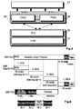
- Fig. 10 also shows the format of a HIPERLAN/2 MAC transmission frame.
- a transmission frame can have a number of broadcast channels (BCH 1 to BCH N), frame control channels (FCH 1 to FCH N), downlink channels (DL 1 to DL N), uplink channels (UL 1 to UL N) as well as random access channels (RCH 1 to RCH N).
- BCH 1 to BCH N broadcast channels
- FCH 1 to FCH N frame control channels
- DL 1 to DL N downlink channels
- UL 1 to UL N uplink channels
- RCH 1 to RCH N random access channels
- the associated time slots of the transmission frame that are reserved for the transmitting station are indicated in the fourth part of Fig. 7 as AS (allocated slots).
- Fig. 7 it is shown in the transmission frame N+1 that the previously collected 1394 bus packets are processed en bloc, that is to say the processing takes place there as described above in connection with Fig. 5. If the reserved time slots AS have a sufficient distance from the start of the transmission frame N+1, the collected and processed data can already be transmitted via the air interface in the next transmission frame N+1.
- the third part of Fig. 7 further indicates that a certain amount of time can elapse between the completion of the processing according to Fig. 5 and transmission of the data via the air interface in order to prepare for the data transmission. It is shown in the transmission frame N+2 that the reserved time slots for the transmitting station have been shifted to a different position by the so-called "scheduler". According to the HIPERLAN/2 standard, this is possible during operation and would be notified in the frame control channel (FCH).
- FCH frame control channel
- Fig. 8 shows the special case where the start of a seventeenth IEEE 1394 bus packet has also been received in the transmission frame N. This can occur due to slight deviations between the two clock systems for the IEEE 1394 bus system on the one hand and for the HIPERLAN/2 transmission system on the other hand. It would then not be possible to perform the SSCS-SDU data processing already after the sixteenth data packet has arrived. It is necessary to wait first for the seventeenth bus packet to arrive. It is therefore shown in the second part of Fig. 8 that the data processing is delayed in comparison with the previous case. As a result, the data can no longer be fully processed when the time slots AS reserved for the transmitting station are ready for transmission. In this case, a delay in data transmission would occur if the data processing were performed in compliance with the standard.
- the received data could then not be transmitted until the next but one data transmission frame N+2. Since, moreover, a seventeenth bus packet has also been received, the space in the assigned time slots in one transmission frame would not be sufficient, and it would even be necessary to transmit the rest of the received data in transmission frame N+3, which is likewise illustrated in Fig. 8 by means of grey hatching.
- a 1394 bus packet can contain a complete MPEG transport packet with 188 bytes. With all additional information of the bus packet, the latter then has a length of 224 bytes.
- said data packet is passed to the processing in the packet-based convergence layer 39.
- the processing steps in the sublayers SSCS, CPCS and SAR are thus performed directly after the respective bus packet has been received. Processing of the received bus packet takes place concurrently with the receiving of further bus packets.
- the individual processing steps are supplied with their own clock signals and are controlled by the central microprocessor unit 38.
- the completed segmented data sections can each be forwarded immediately to the data link control layer (DLC) 36 since they are processed separately in the data link control layer in each case.
- DLC data link control layer
- the time slots in the next transmission frame can also be missed if a seventeenth bus packet already falls within the first transmission frame.
- a seventeenth bus packet was then also started in relation to the advanced processing time-slot pattern, this means that said packet has certainly arrived but before the end of the actual transmission frame, and consequently the processing can still be completed with certainty before the first reserved time slots become valid.
- the processing time-slot pattern must be advanced so far that a complete IEEE 1394 bus packet can still be received and additionally there is still enough time remaining to process this bus packet.
- An implemented solution can be such that it is checked every time after four LCH channels whether data from the current transmission frame has been fully processed and it is then inserted into the remaining LCH time slots.
- This solution enables the available bandwidth to be better utilized so that further resources can be used for control information, e.g. for compensating synchronization differences.
- the buffer memory can be dimensioned for approximately 70 fewer LCH time slots, which is equivalent to a size of 4480 bytes. In the case of a DVC transport stream, this advantage can even be 163 LCH packets, equivalent to 10,432 bytes.
- the invention was explained with reference to the example of the transmission of data received via the IEEE 1394 bus and forwarded via a HIPERLAN/2 interface. It is however not solely restricted to this application.
- the invention can be deployed anywhere where data packets are received via a first interface and are transmitted again via a second interface in a different time-slot pattern.
Landscapes
- Engineering & Computer Science (AREA)
- Computer Networks & Wireless Communication (AREA)
- Signal Processing (AREA)
- Computer Security & Cryptography (AREA)
- Multimedia (AREA)
- Small-Scale Networks (AREA)
- Communication Control (AREA)
- Data Exchanges In Wide-Area Networks (AREA)
- Radio Relay Systems (AREA)
Applications Claiming Priority (2)
| Application Number | Priority Date | Filing Date | Title |
|---|---|---|---|
| DE10343458 | 2003-09-19 | ||
| DE10343458A DE10343458A1 (de) | 2003-09-19 | 2003-09-19 | Verfahren zur Bearbeitung von über eine erste Schnittstelle empfangenen Datenpaketen und Vorrichtung zur Durchführung des Verfahrens |
Publications (3)
| Publication Number | Publication Date |
|---|---|
| EP1517479A2 true EP1517479A2 (de) | 2005-03-23 |
| EP1517479A3 EP1517479A3 (de) | 2008-11-19 |
| EP1517479B1 EP1517479B1 (de) | 2012-07-04 |
Family
ID=34177843
Family Applications (1)
| Application Number | Title | Priority Date | Filing Date |
|---|---|---|---|
| EP04300473A Expired - Lifetime EP1517479B1 (de) | 2003-09-19 | 2004-07-26 | Verfahren zur Verarbeitung von über eine erste Schnittstelle empfangenen Datenpaketen und Vorrichtung zur Durchführung des Verfahrens |
Country Status (8)
| Country | Link |
|---|---|
| US (1) | US7724714B2 (de) |
| EP (1) | EP1517479B1 (de) |
| JP (2) | JP2005102207A (de) |
| KR (1) | KR101125776B1 (de) |
| CN (1) | CN1599360B (de) |
| DE (1) | DE10343458A1 (de) |
| ES (1) | ES2387273T3 (de) |
| MX (1) | MXPA04008879A (de) |
Families Citing this family (7)
| Publication number | Priority date | Publication date | Assignee | Title |
|---|---|---|---|---|
| FR2864870A1 (fr) * | 2004-01-06 | 2005-07-08 | Thomson Licensing Sa | Methode de transmission de donnees ieee 1394 sur une liaison sans fil et appareil implementant la methode |
| JP2005295499A (ja) * | 2004-03-08 | 2005-10-20 | Matsushita Electric Ind Co Ltd | 無線ネットワークにおけるメディアアクセスオーバヘッド低減方法 |
| US7515585B2 (en) * | 2005-01-21 | 2009-04-07 | Ixia | Data communication optimization |
| US20070169152A1 (en) * | 2005-12-30 | 2007-07-19 | Daniel Roodnick | Data and wireless frame alignment for error reduction |
| MY152214A (en) * | 2007-09-27 | 2014-08-29 | Interdigital Patent Holdings | Method and apparatus for supporting segmentation of packets for uplink transmission |
| US8259617B2 (en) * | 2009-03-18 | 2012-09-04 | Broadcom Corporation | Method and system for timely delivery of multimedia content via a femtocell |
| JP2019041182A (ja) * | 2017-08-23 | 2019-03-14 | 株式会社東芝 | 無線通信装置および無線通信方法 |
Citations (2)
| Publication number | Priority date | Publication date | Assignee | Title |
|---|---|---|---|---|
| EP0999671A2 (de) | 1998-11-04 | 2000-05-10 | Sony Corporation | Übertragungsverfahren und -vorrichtung |
| WO2001089152A2 (en) | 2000-05-15 | 2001-11-22 | Thomson Licensing Sa | Method for isochronous data transport over a wireless network |
Family Cites Families (53)
| Publication number | Priority date | Publication date | Assignee | Title |
|---|---|---|---|---|
| US3879580A (en) * | 1972-11-24 | 1975-04-22 | Hughes Aircraft Co | Data terminal for use with TDMA processing repeater |
| US4640986A (en) * | 1983-09-16 | 1987-02-03 | Nec Corporation | Mobile radio communication system |
| US4724537A (en) * | 1984-09-18 | 1988-02-09 | Harris Corporation | Method and apparatus for managing the use of an electronic lock for a mobile radio telephone |
| US4879744A (en) * | 1985-07-10 | 1989-11-07 | Omron Tateisi Electronics Co. | Card-operated telephone |
| FR2593656B1 (fr) * | 1986-01-28 | 1994-04-29 | Parienti Raoul | Procede de communication individuel compact sans fil fonctionnant sur reseau infra-rouge en duplex et son dispositif de mise en oeuvre. |
| US4776003A (en) * | 1986-10-01 | 1988-10-04 | Harris Arlene J | Cellular mobile radio credit card system |
| JPS63254834A (ja) * | 1987-04-13 | 1988-10-21 | Fujitsu Ltd | 自動車電話装置 |
| US4831647A (en) * | 1987-06-02 | 1989-05-16 | Motorola, Inc. | Radiotelephone credit card data communications |
| US4860336A (en) * | 1987-06-02 | 1989-08-22 | Motorola, Inc. | Radiotelephone credit card data communications |
| US5127040A (en) * | 1987-06-02 | 1992-06-30 | Motorola, Inc. | Radiotelephone telephone number down loading |
| US4860341A (en) * | 1987-06-02 | 1989-08-22 | Motorola, Inc. | Radiotelephone credit card call approval synchronization |
| US4905301A (en) * | 1988-07-28 | 1990-02-27 | Motorola, Inc. | Selective system scan for multizone radiotelephone subscriber units |
| CA1317638C (en) * | 1988-09-09 | 1993-05-11 | Stephen B. Meads | Mobile pay telephone system |
| JPH02159156A (ja) * | 1988-12-12 | 1990-06-19 | Sharp Corp | コードレス電話機 |
| US4870679A (en) * | 1988-12-23 | 1989-09-26 | American Telephone And Telegraph Company | Repertory telephone dialer with remote billing capability |
| US4951308A (en) * | 1988-12-29 | 1990-08-21 | Cellular Communications Corporation | Automated vending of cellular hand-held telephones and cellular telephone services |
| US5068891A (en) * | 1989-05-31 | 1991-11-26 | Marshall Marvin E | Credit control system for long distance telephone services |
| SE500289C2 (sv) * | 1989-08-11 | 1994-05-30 | Ericsson Telefon Ab L M | Metod att övervaka telefonabonnemang i ett mobiltelefonsystem |
| EP0452872B1 (de) * | 1990-04-17 | 1996-08-21 | Nec Corporation | Schnurlose Reihenanlage zur Abdeckung mehrerer Bedienungszonen mit exklusiver Zuteilung der Steuerkanäle |
| US5138650A (en) * | 1990-09-27 | 1992-08-11 | Motorola, Inc. | Cordless telephone with internal debit and credit memory |
| US5144649A (en) * | 1990-10-24 | 1992-09-01 | Gte Mobile Communications Service Corporation | Cellular radiotelephone credit card paystation method |
| US5063591A (en) * | 1990-10-26 | 1991-11-05 | Telefonaktiebolaget L M Ericsson | Toll ticketing record generation for billing of intersystem handoff calls in a mobile telephone system |
| US5274368A (en) * | 1991-02-15 | 1993-12-28 | Motorola, Inc. | Method and apparatus for controlling access to a communication system |
| CA2059078C (en) * | 1991-02-27 | 1995-10-03 | Alexander G. Fraser | Mediation of transactions by a communications system |
| US5134651A (en) * | 1991-04-18 | 1992-07-28 | Codecom Rural Communications, Inc. | Method and apparatus for providing answer supervision and an autonomous pay telephone incorporating the same |
| JPH0514555A (ja) * | 1991-07-08 | 1993-01-22 | Toshiba Corp | 公衆コードレス電話装置 |
| US5265155A (en) * | 1991-07-31 | 1993-11-23 | Integrated Communications, Ltd. | Method and apparatus for prepayment of telecommunication connections in a telecommunication switching network |
| US5388148A (en) * | 1991-08-12 | 1995-02-07 | Seiderman; Abe | Cellular telephone calling system using credit card validation |
| US5625669A (en) * | 1991-09-27 | 1997-04-29 | Telemac Cellular Corporation | Mobile phone with internal call accounting controls |
| US5325418A (en) * | 1991-09-27 | 1994-06-28 | Telemac Cellular Corporation | Cellular phone accounting system |
| US5359642A (en) * | 1991-10-30 | 1994-10-25 | International Integrated Communications, Inc. | Method and apparatus for prepayment of telecommunication connections by registered groups of subscribers in a telecommunication switching network |
| CA2076433C (en) * | 1991-10-31 | 1998-08-18 | Brenda B. Amarant | Monitoring of charges debited to an account having an assigned limit |
| US5376931A (en) * | 1992-01-21 | 1994-12-27 | Motorola, Inc. | Debit message authorization system for radio receivers |
| US5222122A (en) * | 1992-03-31 | 1993-06-22 | At&T Bell Laboratories | Payphone having master and slave modes |
| US5359183A (en) * | 1992-04-06 | 1994-10-25 | Rafael Skodlar | Payment card with display |
| US5742760A (en) * | 1992-05-12 | 1998-04-21 | Compaq Computer Corporation | Network packet switch using shared memory for repeating and bridging packets at media rate |
| US5353335A (en) * | 1992-08-03 | 1994-10-04 | At&T Bell Laboratories | Multilingual prepaid telephone system |
| US5359182A (en) * | 1992-10-06 | 1994-10-25 | Interdigital Technology Corporation | Wireless telephone debit card system and method |
| US20020100052A1 (en) * | 1999-01-06 | 2002-07-25 | Daniels John J. | Methods for enabling near video-on-demand and video-on-request services using digital video recorders |
| US5872784A (en) * | 1993-10-20 | 1999-02-16 | Lsi Logic Corporation | High speed single chip digital video network apparatus |
| WO1996008889A1 (en) * | 1994-09-12 | 1996-03-21 | Philips Electronics N.V. | Single frequency transmission network |
| US5642355A (en) * | 1995-09-29 | 1997-06-24 | Telefonaktiebolaget Lm Ericsson | Method of supporting extended range in a TDMA system |
| DE69834492T2 (de) * | 1997-07-15 | 2007-05-10 | Viasat Inc., Carlsbad | Verfahren und vorrichtung zur segmentierung, wiederaufbau und inversem multiplexing von paketen und atm zellen über satelliten/drahtlose netzwerke |
| US6246702B1 (en) * | 1998-08-19 | 2001-06-12 | Path 1 Network Technologies, Inc. | Methods and apparatus for providing quality-of-service guarantees in computer networks |
| JP3519628B2 (ja) * | 1999-01-27 | 2004-04-19 | 株式会社東芝 | 中継装置 |
| JP3075278B1 (ja) * | 1999-02-19 | 2000-08-14 | ソニー株式会社 | 無線通信方法および無線通信装置 |
| SE9902738L (sv) * | 1999-07-19 | 2001-01-20 | Ericsson Telefon Ab L M | Variabel bitrat i kretskopplad väljare |
| CN100499872C (zh) * | 2000-06-02 | 2009-06-10 | 雷迪塞斯公司 | 没有回声消除的ip语音通信的装置和方法 |
| US7310353B1 (en) * | 2000-10-30 | 2007-12-18 | Yair Bourlas | Compression of overhead in layered data communication links |
| JP2002141965A (ja) * | 2000-10-31 | 2002-05-17 | Mcm Japan Kk | ゲートウェイ装置及びその管理サーバ |
| US20020085565A1 (en) * | 2000-12-28 | 2002-07-04 | Maple Optical Systems, Inc. | Technique for time division multiplex forwarding of data streams |
| US7283556B2 (en) * | 2001-07-31 | 2007-10-16 | Nishan Systems, Inc. | Method and system for managing time division multiplexing (TDM) timeslots in a network switch |
| FR2829336A1 (fr) * | 2001-09-04 | 2003-03-07 | Thomson Licensing Sa | Dispositifs de communication pouvant dialoguer sans fil et procedes d'association des dits dispositifs |
-
2003
- 2003-09-19 DE DE10343458A patent/DE10343458A1/de not_active Withdrawn
-
2004
- 2004-07-26 EP EP04300473A patent/EP1517479B1/de not_active Expired - Lifetime
- 2004-07-26 ES ES04300473T patent/ES2387273T3/es not_active Expired - Lifetime
- 2004-09-13 US US10/939,853 patent/US7724714B2/en not_active Expired - Fee Related
- 2004-09-13 MX MXPA04008879A patent/MXPA04008879A/es active IP Right Grant
- 2004-09-14 JP JP2004266855A patent/JP2005102207A/ja active Pending
- 2004-09-16 CN CN200410078674XA patent/CN1599360B/zh not_active Expired - Fee Related
- 2004-09-17 KR KR1020040074737A patent/KR101125776B1/ko not_active Expired - Fee Related
-
2011
- 2011-11-07 JP JP2011243545A patent/JP5394464B2/ja not_active Expired - Fee Related
Patent Citations (2)
| Publication number | Priority date | Publication date | Assignee | Title |
|---|---|---|---|---|
| EP0999671A2 (de) | 1998-11-04 | 2000-05-10 | Sony Corporation | Übertragungsverfahren und -vorrichtung |
| WO2001089152A2 (en) | 2000-05-15 | 2001-11-22 | Thomson Licensing Sa | Method for isochronous data transport over a wireless network |
Also Published As
| Publication number | Publication date |
|---|---|
| MXPA04008879A (es) | 2005-07-01 |
| CN1599360A (zh) | 2005-03-23 |
| KR101125776B1 (ko) | 2012-03-28 |
| EP1517479B1 (de) | 2012-07-04 |
| JP5394464B2 (ja) | 2014-01-22 |
| EP1517479A3 (de) | 2008-11-19 |
| JP2005102207A (ja) | 2005-04-14 |
| US20050063405A1 (en) | 2005-03-24 |
| JP2012055002A (ja) | 2012-03-15 |
| CN1599360B (zh) | 2010-08-25 |
| ES2387273T3 (es) | 2012-09-19 |
| US7724714B2 (en) | 2010-05-25 |
| KR20050028874A (ko) | 2005-03-23 |
| DE10343458A1 (de) | 2005-05-12 |
Similar Documents
| Publication | Publication Date | Title |
|---|---|---|
| US7103012B2 (en) | Multiple access communication system and data transceiver | |
| JP5394464B2 (ja) | 第一のインタフェースを介して受信されたデータパケットを処理する方法、及び当該方法を実行する装置 | |
| US6055242A (en) | Method and apparatus enabling synchronous transfer mode, variable length and packet mode access for multiple services over a broadband communication network | |
| EP1484873B1 (de) | Verfahren und System zur Durchführung schnurloser Kommunikation durch Erzeugen und Senden eines Zeitinformation und Sendeabfolge beinhaltenden Zeiteinteilungsplans | |
| EP2958393B1 (de) | Verteilung von broadcast/multicast-daten in telekommunikationssystemen | |
| KR101554857B1 (ko) | Pdu를 생성하기 위한 방법 및 장치 및 이의 기지국 | |
| US8494001B2 (en) | Concatenated frame structure for data transmission | |
| JP2002532955A (ja) | マルチ・パンクチャドfec手法 | |
| US6414967B2 (en) | Transmission system with flexible frame structure | |
| US20110200130A1 (en) | Method and apparatus for transmitting/receiving data in mu-mimo system | |
| CN106533537A (zh) | 地面站遥控指令注入卫星的方法 | |
| JP3357282B2 (ja) | パケット送信方法 | |
| EP1282959B1 (de) | Verfahren zur isochronen datenübertragung über ein drahtloses netzwerk | |
| KR100922021B1 (ko) | 통신 네트워크, 통신 네트워크에서 통신하는 노드, 및 통신 네크워크에서 노드들간의 통신을 제어하는 방법 | |
| CN101990245B (zh) | 一种用于中继链路的传输方法、传输装置及接收装置 | |
| US20020009055A1 (en) | Method of controlling transimission and apparatus for controlling transmission | |
| WO2021065915A1 (ja) | フレーム生成方法およびフレーム生成装置 | |
| JP2001257706A (ja) | 伝送制御方法および伝送制御装置 | |
| US20020009154A1 (en) | Network management method, wireless transmission method and wireless transmission apparatus | |
| JP3655259B2 (ja) | ネットワーク無線中継装置及びネットワーク無線中継方法 | |
| US20010036836A1 (en) | Radio transmission method and radio transmission apparatus | |
| KR100281649B1 (ko) | 무선 에이티엠 엘에이엔 시스템에서의 매체접근제어 처리장치 | |
| JP4868635B2 (ja) | 無線伝送方法および無線伝送装置 | |
| JP2002111685A (ja) | 無線伝送方法、無線伝送装置および無線伝送システム | |
| JP2001203716A (ja) | データ伝送方法およびデータ伝送システム並びに当該システムに用いる装置 |
Legal Events
| Date | Code | Title | Description |
|---|---|---|---|
| PUAI | Public reference made under article 153(3) epc to a published international application that has entered the european phase |
Free format text: ORIGINAL CODE: 0009012 |
|
| AK | Designated contracting states |
Kind code of ref document: A2 Designated state(s): AT BE BG CH CY CZ DE DK EE ES FI FR GB GR HU IE IT LI LU MC NL PL PT RO SE SI SK TR |
|
| AX | Request for extension of the european patent |
Extension state: AL HR LT LV MK |
|
| RAP1 | Party data changed (applicant data changed or rights of an application transferred) |
Owner name: THOMSON LICENSING |
|
| PUAL | Search report despatched |
Free format text: ORIGINAL CODE: 0009013 |
|
| AK | Designated contracting states |
Kind code of ref document: A3 Designated state(s): AT BE BG CH CY CZ DE DK EE ES FI FR GB GR HU IE IT LI LU MC NL PL PT RO SE SI SK TR |
|
| AX | Request for extension of the european patent |
Extension state: AL HR LT LV MK |
|
| 17P | Request for examination filed |
Effective date: 20090424 |
|
| AKX | Designation fees paid |
Designated state(s): DE ES FR GB IT |
|
| 17Q | First examination report despatched |
Effective date: 20090805 |
|
| RAP1 | Party data changed (applicant data changed or rights of an application transferred) |
Owner name: THOMSON LICENSING |
|
| GRAP | Despatch of communication of intention to grant a patent |
Free format text: ORIGINAL CODE: EPIDOSNIGR1 |
|
| GRAS | Grant fee paid |
Free format text: ORIGINAL CODE: EPIDOSNIGR3 |
|
| GRAA | (expected) grant |
Free format text: ORIGINAL CODE: 0009210 |
|
| AK | Designated contracting states |
Kind code of ref document: B1 Designated state(s): DE ES FR GB IT |
|
| REG | Reference to a national code |
Ref country code: GB Ref legal event code: FG4D |
|
| REG | Reference to a national code |
Ref country code: DE Ref legal event code: R096 Ref document number: 602004038424 Country of ref document: DE Effective date: 20120823 |
|
| REG | Reference to a national code |
Ref country code: DE Ref legal event code: R084 Ref document number: 602004038424 Country of ref document: DE Effective date: 20120707 |
|
| REG | Reference to a national code |
Ref country code: ES Ref legal event code: FG2A Ref document number: 2387273 Country of ref document: ES Kind code of ref document: T3 Effective date: 20120919 |
|
| PLBE | No opposition filed within time limit |
Free format text: ORIGINAL CODE: 0009261 |
|
| STAA | Information on the status of an ep patent application or granted ep patent |
Free format text: STATUS: NO OPPOSITION FILED WITHIN TIME LIMIT |
|
| 26N | No opposition filed |
Effective date: 20130405 |
|
| REG | Reference to a national code |
Ref country code: DE Ref legal event code: R097 Ref document number: 602004038424 Country of ref document: DE Effective date: 20130405 |
|
| REG | Reference to a national code |
Ref country code: FR Ref legal event code: PLFP Year of fee payment: 13 |
|
| REG | Reference to a national code |
Ref country code: FR Ref legal event code: PLFP Year of fee payment: 14 |
|
| REG | Reference to a national code |
Ref country code: DE Ref legal event code: R082 Ref document number: 602004038424 Country of ref document: DE Representative=s name: DEHNS, DE Ref country code: DE Ref legal event code: R082 Ref document number: 602004038424 Country of ref document: DE Representative=s name: HOFSTETTER, SCHURACK & PARTNER PATENT- UND REC, DE |
|
| REG | Reference to a national code |
Ref country code: FR Ref legal event code: PLFP Year of fee payment: 15 |
|
| REG | Reference to a national code |
Ref country code: DE Ref legal event code: R082 Ref document number: 602004038424 Country of ref document: DE Representative=s name: DEHNS, DE Ref country code: DE Ref legal event code: R081 Ref document number: 602004038424 Country of ref document: DE Owner name: INTERDIGITAL CE PATENT HOLDINGS SAS, FR Free format text: FORMER OWNER: THOMSON LICENSING SAS, ISSY-LES-MOULINEAUX, FR |
|
| REG | Reference to a national code |
Ref country code: ES Ref legal event code: PC2A Owner name: INTERDIGITAL CE PATENT HOLDINGS Effective date: 20190702 |
|
| REG | Reference to a national code |
Ref country code: GB Ref legal event code: 732E Free format text: REGISTERED BETWEEN 20190926 AND 20191002 |
|
| PGFP | Annual fee paid to national office [announced via postgrant information from national office to epo] |
Ref country code: IT Payment date: 20190725 Year of fee payment: 16 Ref country code: FR Payment date: 20190725 Year of fee payment: 16 Ref country code: ES Payment date: 20190826 Year of fee payment: 16 |
|
| PGFP | Annual fee paid to national office [announced via postgrant information from national office to epo] |
Ref country code: GB Payment date: 20190729 Year of fee payment: 16 |
|
| PGFP | Annual fee paid to national office [announced via postgrant information from national office to epo] |
Ref country code: DE Payment date: 20190930 Year of fee payment: 16 |
|
| REG | Reference to a national code |
Ref country code: DE Ref legal event code: R119 Ref document number: 602004038424 Country of ref document: DE |
|
| GBPC | Gb: european patent ceased through non-payment of renewal fee |
Effective date: 20200726 |
|
| PG25 | Lapsed in a contracting state [announced via postgrant information from national office to epo] |
Ref country code: FR Free format text: LAPSE BECAUSE OF NON-PAYMENT OF DUE FEES Effective date: 20200731 Ref country code: GB Free format text: LAPSE BECAUSE OF NON-PAYMENT OF DUE FEES Effective date: 20200726 |
|
| PG25 | Lapsed in a contracting state [announced via postgrant information from national office to epo] |
Ref country code: DE Free format text: LAPSE BECAUSE OF NON-PAYMENT OF DUE FEES Effective date: 20210202 |
|
| PG25 | Lapsed in a contracting state [announced via postgrant information from national office to epo] |
Ref country code: IT Free format text: LAPSE BECAUSE OF NON-PAYMENT OF DUE FEES Effective date: 20200726 |
|
| REG | Reference to a national code |
Ref country code: ES Ref legal event code: FD2A Effective date: 20211229 |
|
| PG25 | Lapsed in a contracting state [announced via postgrant information from national office to epo] |
Ref country code: ES Free format text: LAPSE BECAUSE OF NON-PAYMENT OF DUE FEES Effective date: 20200727 |