EP1517462A2 - Compensateur de dispersion accordable - Google Patents
Compensateur de dispersion accordable Download PDFInfo
- Publication number
- EP1517462A2 EP1517462A2 EP04255426A EP04255426A EP1517462A2 EP 1517462 A2 EP1517462 A2 EP 1517462A2 EP 04255426 A EP04255426 A EP 04255426A EP 04255426 A EP04255426 A EP 04255426A EP 1517462 A2 EP1517462 A2 EP 1517462A2
- Authority
- EP
- European Patent Office
- Prior art keywords
- mzi
- tdc
- optical signal
- coupler
- dispersion
- Prior art date
- Legal status (The legal status is an assumption and is not a legal conclusion. Google has not performed a legal analysis and makes no representation as to the accuracy of the status listed.)
- Granted
Links
Images

Classifications
-
- G—PHYSICS
- G02—OPTICS
- G02B—OPTICAL ELEMENTS, SYSTEMS OR APPARATUS
- G02B6/00—Light guides; Structural details of arrangements comprising light guides and other optical elements, e.g. couplings
- G02B6/10—Light guides; Structural details of arrangements comprising light guides and other optical elements, e.g. couplings of the optical waveguide type
- G02B6/12—Light guides; Structural details of arrangements comprising light guides and other optical elements, e.g. couplings of the optical waveguide type of the integrated circuit kind
- G02B6/12007—Light guides; Structural details of arrangements comprising light guides and other optical elements, e.g. couplings of the optical waveguide type of the integrated circuit kind forming wavelength selective elements, e.g. multiplexer, demultiplexer
-
- G—PHYSICS
- G02—OPTICS
- G02B—OPTICAL ELEMENTS, SYSTEMS OR APPARATUS
- G02B6/00—Light guides; Structural details of arrangements comprising light guides and other optical elements, e.g. couplings
- G02B6/24—Coupling light guides
- G02B6/26—Optical coupling means
- G02B6/28—Optical coupling means having data bus means, i.e. plural waveguides interconnected and providing an inherently bidirectional system by mixing and splitting signals
- G02B6/293—Optical coupling means having data bus means, i.e. plural waveguides interconnected and providing an inherently bidirectional system by mixing and splitting signals with wavelength selective means
- G02B6/29346—Optical coupling means having data bus means, i.e. plural waveguides interconnected and providing an inherently bidirectional system by mixing and splitting signals with wavelength selective means operating by wave or beam interference
- G02B6/2935—Mach-Zehnder configuration, i.e. comprising separate splitting and combining means
- G02B6/29352—Mach-Zehnder configuration, i.e. comprising separate splitting and combining means in a light guide
- G02B6/29355—Cascade arrangement of interferometers
-
- G—PHYSICS
- G02—OPTICS
- G02B—OPTICAL ELEMENTS, SYSTEMS OR APPARATUS
- G02B6/00—Light guides; Structural details of arrangements comprising light guides and other optical elements, e.g. couplings
- G02B6/24—Coupling light guides
- G02B6/26—Optical coupling means
- G02B6/28—Optical coupling means having data bus means, i.e. plural waveguides interconnected and providing an inherently bidirectional system by mixing and splitting signals
- G02B6/293—Optical coupling means having data bus means, i.e. plural waveguides interconnected and providing an inherently bidirectional system by mixing and splitting signals with wavelength selective means
- G02B6/29379—Optical coupling means having data bus means, i.e. plural waveguides interconnected and providing an inherently bidirectional system by mixing and splitting signals with wavelength selective means characterised by the function or use of the complete device
- G02B6/29392—Controlling dispersion
- G02B6/29394—Compensating wavelength dispersion
-
- G—PHYSICS
- G02—OPTICS
- G02B—OPTICAL ELEMENTS, SYSTEMS OR APPARATUS
- G02B6/00—Light guides; Structural details of arrangements comprising light guides and other optical elements, e.g. couplings
- G02B6/24—Coupling light guides
- G02B6/26—Optical coupling means
- G02B6/28—Optical coupling means having data bus means, i.e. plural waveguides interconnected and providing an inherently bidirectional system by mixing and splitting signals
- G02B6/293—Optical coupling means having data bus means, i.e. plural waveguides interconnected and providing an inherently bidirectional system by mixing and splitting signals with wavelength selective means
- G02B6/29379—Optical coupling means having data bus means, i.e. plural waveguides interconnected and providing an inherently bidirectional system by mixing and splitting signals with wavelength selective means characterised by the function or use of the complete device
- G02B6/29395—Optical coupling means having data bus means, i.e. plural waveguides interconnected and providing an inherently bidirectional system by mixing and splitting signals with wavelength selective means characterised by the function or use of the complete device configurable, e.g. tunable or reconfigurable
-
- G—PHYSICS
- G02—OPTICS
- G02F—OPTICAL DEVICES OR ARRANGEMENTS FOR THE CONTROL OF LIGHT BY MODIFICATION OF THE OPTICAL PROPERTIES OF THE MEDIA OF THE ELEMENTS INVOLVED THEREIN; NON-LINEAR OPTICS; FREQUENCY-CHANGING OF LIGHT; OPTICAL LOGIC ELEMENTS; OPTICAL ANALOGUE/DIGITAL CONVERTERS
- G02F1/00—Devices or arrangements for the control of the intensity, colour, phase, polarisation or direction of light arriving from an independent light source, e.g. switching, gating or modulating; Non-linear optics
- G02F1/01—Devices or arrangements for the control of the intensity, colour, phase, polarisation or direction of light arriving from an independent light source, e.g. switching, gating or modulating; Non-linear optics for the control of the intensity, phase, polarisation or colour
- G02F1/21—Devices or arrangements for the control of the intensity, colour, phase, polarisation or direction of light arriving from an independent light source, e.g. switching, gating or modulating; Non-linear optics for the control of the intensity, phase, polarisation or colour by interference
- G02F1/225—Devices or arrangements for the control of the intensity, colour, phase, polarisation or direction of light arriving from an independent light source, e.g. switching, gating or modulating; Non-linear optics for the control of the intensity, phase, polarisation or colour by interference in an optical waveguide structure
-
- H—ELECTRICITY
- H04—ELECTRIC COMMUNICATION TECHNIQUE
- H04B—TRANSMISSION
- H04B10/00—Transmission systems employing electromagnetic waves other than radio-waves, e.g. infrared, visible or ultraviolet light, or employing corpuscular radiation, e.g. quantum communication
- H04B10/25—Arrangements specific to fibre transmission
- H04B10/2507—Arrangements specific to fibre transmission for the reduction or elimination of distortion or dispersion
- H04B10/2513—Arrangements specific to fibre transmission for the reduction or elimination of distortion or dispersion due to chromatic dispersion
- H04B10/25133—Arrangements specific to fibre transmission for the reduction or elimination of distortion or dispersion due to chromatic dispersion including a lumped electrical or optical dispersion compensator
-
- G—PHYSICS
- G02—OPTICS
- G02B—OPTICAL ELEMENTS, SYSTEMS OR APPARATUS
- G02B6/00—Light guides; Structural details of arrangements comprising light guides and other optical elements, e.g. couplings
- G02B6/24—Coupling light guides
- G02B6/26—Optical coupling means
- G02B6/28—Optical coupling means having data bus means, i.e. plural waveguides interconnected and providing an inherently bidirectional system by mixing and splitting signals
- G02B6/293—Optical coupling means having data bus means, i.e. plural waveguides interconnected and providing an inherently bidirectional system by mixing and splitting signals with wavelength selective means
- G02B6/29379—Optical coupling means having data bus means, i.e. plural waveguides interconnected and providing an inherently bidirectional system by mixing and splitting signals with wavelength selective means characterised by the function or use of the complete device
- G02B6/2938—Optical coupling means having data bus means, i.e. plural waveguides interconnected and providing an inherently bidirectional system by mixing and splitting signals with wavelength selective means characterised by the function or use of the complete device for multiplexing or demultiplexing, i.e. combining or separating wavelengths, e.g. 1xN, NxM
-
- G—PHYSICS
- G02—OPTICS
- G02B—OPTICAL ELEMENTS, SYSTEMS OR APPARATUS
- G02B6/00—Light guides; Structural details of arrangements comprising light guides and other optical elements, e.g. couplings
- G02B6/24—Coupling light guides
- G02B6/26—Optical coupling means
- G02B6/28—Optical coupling means having data bus means, i.e. plural waveguides interconnected and providing an inherently bidirectional system by mixing and splitting signals
- G02B6/293—Optical coupling means having data bus means, i.e. plural waveguides interconnected and providing an inherently bidirectional system by mixing and splitting signals with wavelength selective means
- G02B6/29379—Optical coupling means having data bus means, i.e. plural waveguides interconnected and providing an inherently bidirectional system by mixing and splitting signals with wavelength selective means characterised by the function or use of the complete device
- G02B6/29398—Temperature insensitivity
-
- G—PHYSICS
- G02—OPTICS
- G02F—OPTICAL DEVICES OR ARRANGEMENTS FOR THE CONTROL OF LIGHT BY MODIFICATION OF THE OPTICAL PROPERTIES OF THE MEDIA OF THE ELEMENTS INVOLVED THEREIN; NON-LINEAR OPTICS; FREQUENCY-CHANGING OF LIGHT; OPTICAL LOGIC ELEMENTS; OPTICAL ANALOGUE/DIGITAL CONVERTERS
- G02F2201/00—Constructional arrangements not provided for in groups G02F1/00 - G02F7/00
- G02F2201/16—Constructional arrangements not provided for in groups G02F1/00 - G02F7/00 series; tandem
Definitions
- This invention relates generally to optical dispersion compensators and, more particularly, to a method and apparatus for implementing a colorless Mach-Zehnder-interferometer- based tunable dispersion compensator.
- Optical signal dispersion compensators can correct for chromatic dispersion in optical fiber and are especially useful for bit rates 10 Gb/s and higher. Furthermore, it is advantageous for the dispersion compensator to have an adjustable amount of dispersion, facilitating system installation. It is also advantageous if the tunable dispersion compensator (TDC) is colorless, i.e., one device can compensate many channels simultaneously or be selectable to compensate any channel in the system.
- TDC tunable dispersion compensator
- Previously proposed colorless TDCs include ring resonators [1] , the virtually imaged phased array (VIPA) [2] , cascaded Mach-Zehnder interferometers (MZIs) [3,4,5] , temperature-tuned etalons [6] , waveguide grating routers (WGRs) with thermal lenses [7] , and bulk gratings with deformable mirrors [8] .
- the bracketed references [] refer to publications listed in the attached Reference list.
- the cascaded MZI approach is particularly promising since it exhibits low loss, can be made with standard silica waveguides, and can be compact.
- I disclose a method and apparatus for implementing a colorless polarization independent Mach-Zehnder-interferometer (MZI)-based tunable dispersion compensator (TDC) that has only three MZI stages (two in a reflective version) and two adjustable couplers which are responsive to one control voltage, making it compact, low power, and simple to fabricate, test, and operate.
- MZI Mach-Zehnder-interferometer
- TDC tunable dispersion compensator
- Such an MZI-based TDC with a 25-GHz-free-spectral-range version can compensate ⁇ ⁇ 2100 ps/nm for 10 Gb/s signals.
- Having a free-spectral range equal to the system channel spacing divided by an integer makes it possible for the TDC to compensate many channels either simultaneously and also compensate the case where the wavelength is jumping between different channels without adjustment of the TDC.
- the 25 GHz free-spectral range, as well as the free-spectral ranges 20 GHz and 33.3 GHz will allow for the TDC to compensate multiple channels on a 100-GHz grid
- one embodiment of my tunable chromatic optical signal dispersion compensator comprises a first MZI including a fixed 50/50 coupler for receiving an input optical signal, a second MZI including a first adjustable coupler that is shared with the first MZI and a second adjustable coupler that is shared a third MZI, the second MZI further including a half-wave plate positioned across the midpoints of the two path lengths of the second MZI so as to exchange the TE and TM polarizations of the optical signals passing through the two path lengths, the third MZI including a fixed 50/50 coupler for outputting a dispersion-adjusted output optical signal and wherein said first and second shared adjustable couplers are adjusted with equal coupling ratios using a single control signal to provide adjustable dispersion compensation to the output signal.
- my tunable chromatic optical signal dispersion compensator comprises a first MZI including a fixed 50/50 coupler for receiving an input optical signal at a first port and an adjustable coupler, that is shared with a second reflective MZI, the path-length difference between the two arms in the second MZI is equal to that of the first MZI and wherein the adjustable coupler is responsive to a control signal for controlling the amount of signal dispersion added by said compensator to the input optical signal to form the output optical signal.
- a quarter-wave plate is positioned in front of the reflective facet of the second reflective MZI.
- a polarizationindependent cascaded MZI-TDC arrangement is formed by cascading a first three-stage MZI-TDC with an second three-stage MZI-TDC with a half-wave plate between the two TDCs.
- a double-pass MZI-TDC arrangement is formed by placing a reflector after the TDC such that the signal passes through the TDC twice. This double-pass increases the amount of achievable dispersion. If polarization independence is desired, a quarter-wave plate can be placed between the TDC and the reflector.
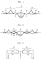
- Fig. 1 there is shown, in accordance with the present invention, an illustrative diagram of my polarization independent tunable dispersion compensator (TDC) device that has only three stages and uses one control voltage.
- the three stages 103, 105, and 107 are implemented using Mach-Zehnder-interferometers (MZIs).
- MZIs Mach-Zehnder-interferometers
- the first and second MZIs 103, 105 share an adjustable coupler 104 and the second and third MZIs 105, 107 share an adjustable coupler 106.
- the two adjustable couplers 104, 106 are always set equally.
- the first and third MZI have path-length differences ⁇ L, and the center MZI has a path-length difference of 2 ⁇ L (plus any phase offset from the couplers).
- the longer path-length is located in the top, bottom, and top arms of the first, second and third MZIs, 103, 105, 107, respectively. This allows the structure to be folded into a compact arrangement as shown in the waveguide layout of Fig. 10.
- the longer path-length could be located in the top arm of the first, second and third MZIs.
- My polarization independent TDC is achieved in a cost-effective and low loss approach by placing a half-wave plate 110 in the center of the TDC device (center of second MZI 105).
- a half-wave plate 110 refers to a thin birefringent waveplate that gives a differential phase shift between orthogonal polarizations of 180°
- the waveplate birefrefirngent axes are oriented at 45° to the plane of the lightwave circuit.
- Takahashi, et. al. were the first to use a half-wave plate, made of quartz, in a groove in the center of a symmetric waveguide device to achieve low polarization sensitivity [5C] .
- the half-wave plate 110 exchanges the signals in the TE and TM polarizations in the TDC device center, so if the device is symmetric (as in Fig. 1), and there is no polarization coupling between TE and TM elsewhere in the TDC device, polarization dependence is eliminated.
- the silica waveguide arms of the length-imbalanced MZIs 103, 105, 107 exhibit a stress-induced birefringence, causing the accumulated phase difference in length-imbalanced MZIs to be different for transverse-electric (TE) and transverse-magnetic (TM) polarized lightwaves.
- TE transverse-electric
- TM transverse-magnetic
- the TDC for a 10 Gb/s signal with a free-spectral range of 25 GHz requires a path-length difference > 1.6 cm, making the TDC PLC highly polarization dependent, even if I use waveguides with state-of-the-art PDW for silica-on-silicon of 20 pm [5B] .
- the half-wave plate 110 rotates the TM polarized lightwave so that it becomes the TE polarized lightwave over the second half, 105B, of MZI 105 and MZI 107.
- the waveplate 110 in my design even cancels out coupler and phase-shifter polarization dependencies, unlike the general cascaded MZI TDC.
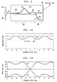
- Figs. 5A and 5B compare the simulated transmissivity and group delay for the perfect case 501, and the misaligned case,502, where the outer MZIs 103, 107 are misaligned by 20 pm in a 25-GHz-free-spectral-range device. As shown by 502, a small frequency offset between the outermost MZIs results in mainly a higher loss.
- My polarization independent TDC is shown in Fig. 1. It consists of three MZIs 103, 105, and 107 coupled together with two adjustable couplers 104 and 106, each made of a small MZI, that are always set equally. When the phase shifters (of couplers 104 and 106) are not driven, the adjustable couplers 104 and 106 are 100/0, and the device looks like a large length-balanced interferometer, having unity transmission and flat group delay over all wavelengths. When both upper phase shifters (e.g., 202 of Fig.
- the couplers are tuned toward 50/50, and MZI 103 act like a demultiplexer and MZI 106 acts like a multiplexer, splitting the light so that shorter wavelengths predominantly travel the longer path of the center MZI, giving negative dispersion. It is vice-versa for driving the two lower phase shifters (e.g., 203 of Fig. 2).
- the adjustable couplers 104 and 106 are exactly 50/50, the design is similar to the fixed birefringent crystal dispersion compensator of Ref. [ 9 ].
- a more detailed description of the dispersion compensating TDC of Fig. 1 is as follows.
- An input optical signal at port 101 is split equally to the two arms of the first MZI 103 by the y-branch coupler 102.
- one arm is longer, by ⁇ L, than the other arm so that when the optical signals are recombined in the first adjustable coupler 104, the amount of light sent to each of the two arms of the second MZI 105 depends on the wavelength.
- the first adjustable coupler 104 in response to a control signal C1 controls the sign and amount of dispersion introduced to the signals outputted from the coupler 104 to the arms of the second MZI 105.
- the second adjustable coupler 106 in response to a control signal C1 controls the sign and amount of dispersion introduced to the signals received from the arms of the second MZI 105 and outputted from the coupler 106 to the arms of the third MZI 107.
- a predetermined control signal C1 to adjustable couplers 104, 106 is used to enable the shorter wavelengths to predominantly travel the longer arms of the second MZI 105.
- a predetermined control signal C1 to adjustable couplers 104, 106 is used to enable the longer wavelengths to predominantly travel the longer arms of the second MZI 105.
- the third MZI 107 then performs a function similar to the first MZI in that the wavelengths on its arms are recombined in the final y-branch coupler 108 and are sent to the output port 109.
- the two adjustable couplers 104, 106 are 100/0 (i.e., the couplers perform a simple cross-connect function --an input to the upper left-hand port of the adjustable coupler goes to the lower right-hand output port of the adjustable coupler and vice versa).
- the optical signals through the TDC traverse equal path lengths. While only the differential arm lengths are shown in Fig. 1, in MZIs 103 and 107, the actual arm lengths are L+ ⁇ L and L and in MZI the actual arm lengths are L+2 ⁇ L and L.
- the signal path from one output port of y-branch coupler 102 to the output port 109 of y-branch coupler 108 follows a path of length L+ ⁇ L through MZI 103, L through MZI 105, and L+ ⁇ L through MZI 107, giving a total length of 3L+2 ⁇ L; and the other path consists of L, L+2 ⁇ L, and L, also giving a total length of 3L+2 ⁇ L.
- the TDC device acts simply as a waveguide of length 3L+2 ⁇ L and so introduces no significant chromatic dispersion.
- ⁇ L determines the free spectral range (FSR) of the TDC.
- the FSR would be about 25-GHz.
- Such an MZI-based TDC with a 25-GHz-free-spectral-range version can compensate ⁇ ⁇ 2100 ps/nm for 10 Gb/s signals.
- having a FSR equal to the system wavelength channel spacing divided by an integer makes it possible for the TDC to compensate many channels simultaneously.
- my TDC is colorless, i.e., it can compensate many channels simultaneously or be selectable to compensate any channel in a multi-wavelength channel system.
- Other reasonable choices for the FSR include 20 GHz and 33.3 GHz to compensate 10 Gb/s channels with a 100-GHz-spaced channel wavelength grid.
- MZIs 103, 105, 107 may be implemented together as a planar optical integrated circuit or may be implemented using discrete optical elements mounted on a substrate.
- the dispersion of TDC can be tuned positive or negative by adjusting couplers 104 and 106 toward 50/50 using a control signal C1. As will be discussed with reference to Fig 3, by selecting a control signal C1 that is higher or lower that the zero dispersion control signal C1 setting, TDC can be set to a positive or negative dispersion level.
- adjustable couplers 104 and 106 are controlled by a common control signal C1, if desirable separate control signals may be used. Separate controls could be useful, for example, if the couplers have unequal characteristics due to fabrication non-uniformities.
- Fig. 2 illustrates, in accordance with the present invention, a TDC of Fig. 1 where the adjustable couplers 104 and 106 are implemented using two MZI-based adjustable couplers. As shown, the adjustable couplers 104, 106 are implemented using small MZIs with controllable phase shifters.
- Each MZI includes a 50/50 fixed evanescent coupler 201, upper phase shifter 202, lower phase shifter 203, and 50/50 fixed evanescent coupler 204.
- Driving both the lower phase shifters 203 of both MZIs with the same control signal C1 at a first level pushes the dispersion in one direction, and driving both upper phase shifters 202 at a second level pushes the dispersion in the other direction.
- the adjustable couplers 104 and 106 may have post-fabricated permanent adjustments made to their MZIs so as to more accurately compensate for any variations therein
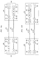
- phase shifters 202, 203 are thermooptic heaters, then a convenient electrical layout that requires only one control signal C1 to tune to both positive and negative dispersion is shown in Fig. 3.
- the control signal C1 voltage is varied between the levels V1 and V2, where V2 is greater than V1.
- control voltage C1 is at a predetermined zero dispersion level Vz between V1 and V2, then the same current flows through both the upper and lower phase shifters establishing zero dispersion and, hence, adjustable couplers 202, 203 perform a simple cross-connect function as discussed previously.
- control signal C1 When control signal C1 is at level V1 then no current flows through the upper phase shifters 202 and current flows through the lower phase shifters 203 establishing the maximum amount of a dispersion of a first polarity.
- control signal C1 When the desired dispersion level is somewhere between zero dispersion level Vz and the maximum first polarity dispersion level V1, then control signal C1 is suitably adjusted to a voltage level between V1 and Vz.
- the upper 202 and lower 203 phase shifters are operated in a push-pull arrangement. That is, for example, in the upper phase shifter 202 current is increasing while in the lower phase shifter current is decreasing.
- control signal C1 When control signal C1 is at level V2 then no current flows through the lower phase shifters 202 and current flows through the upper phase shifters 203 establishing the maximum amount of a dispersion of a second polarity.
- control signal C1 When the desired dispersion level is somewhere between zero dispersion level Vz and the maximum second polarity dispersion level V2, then control signal C1 is suitably adjusted to a voltage level between Vz and V2.
- This push-pull operation of the upper 202 and lower 203 phase shifters results in a low worst-case thermooptic power consumption and roughly constant power dissipation for all tuning settings [10] .
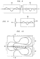
- a reflective design of a tunable dispersion compensator that also uses only one control voltage. Since the TDC arrangement of Fig. 1 is symmetric, as shown in Fig. 4 it can be implemented using a simpler reflective design, at the expense of requiring a circulator.
- MZI 403 performs the function of the first 103 and third 107 MZIs of Fig. 1 and reflective MZI 405 performs the function of MZI 105 of Fig. 1.
- a polarization-independence reflective TDC is desired, it can be obtained by adding a quarter-wave plate 410 located in front of the reflective facet 406. Because the optical signals pass twice through the quarter-wave plate 410 it has the same effect as the half-wave plate 110 of Fig. 1.
- the operation of the reflective TDC is as follows.
- An input optical signal at port 400 passes through circulator 401 and is split equally to the two arms of the MZI 403 by the y-branch coupler 412.
- one arm is longer, by ⁇ L, than the other arm so that when the optical signals are recombined in the first adjustable coupler 404, the amount of light sent to each of the two arms of the reflective MZI 405 depends on the wavelength.
- the adjustable coupler 404 operates in response to a control signal C1 that controls both the sign and amount of dispersion introduced to the signals outputted from the coupler 404 to the arms 407, 408 of the reflective MZI 405 and also establishes the same sign and amount of dispersion introduced to the signals outputted from the coupler 404 to the arms of MZI 403.
- the reflective MZI 405 has a reflective facet 406 for reflecting signals received from the two arms 407 and 408 back to these arms.
- Multi-section evanescent couplers can give a more accurate 50/50 splitting ratio in the face of wavelength, polarization, and fabrication changes. Another possibility is to use multimode interference couplers.
- couplers 102 and 108 could be other 50/50 couplers than y-branch couplers. For instance, they could be multimode interference couplers.
- Fig. 5A shows the simulated transmissivity
- Fig. 5B shows the simulated group delay characteristic through my TDC at three different settings (0, + ⁇ /2, - ⁇ /2) of the adjustable couplers (s) of Figs. 1 and 4.
- the free-spectral range is 25 GHz, at the limits and center of the tuning range.
- the wavelength is 1550 nm.
- the marked phases denote the phase difference between the MZI arms in the tunable couplers of Fig. 2. The loss is theoretically zero and does not increase at the channel center as the dispersion is tuned away from zero.
- the dispersion At maximum dispersion, there is a transmissivity ripple of 1.25 dB peak-to-peak; the dispersion reaches ⁇ 2500 ps/nm.
- the bandwidth is not very wide, though: the transmitter frequency error must be less than ⁇ 2.5 GHz ( ⁇ 20 pm). This is achievable for wavelength-locked transmitters. Practically, for 10 Gb/s signals in this case the dispersion is limited to ⁇ 2100 ps/nm when the FSR is 25 GHz.
- the TDC has a relatively narrow bandwidth. If wavelength-locked transmitter lasers are employed in the system, this bandwidth is generally adequate. However, in some systems, the uncertainty in the laser wavelength may be too large for the TDC bandwidth. In such a case, one can lock of the TDC to the laser wavelength by adjusting phase shifters in the two outermost MZIs. For instance, by increasing the drive to phase shifters in both longer arms of the two outermost MZIs in unison, one can tune the TDC to longer wavelengths.
- the feedback for the locking can be derived by dithering these phase shifters in the outermost MZIs in unison at a specific frequency and measuring the output power from the TDC using a tap and a photodetector, employing a standard peak-detection feedback control.
- FIGs. 6A and 6B show the use of my TDC in illustrative optical transmission systems.
- Figure 6A shows a pre-transmission dispersion compensation system where the first location 600 includes an optical transmitter unit 601, a TDC 602 used for pre-transmission dispersion compensation, an optical amplifier 603, and a wavelength multiplexer 604, if needed.
- the output signal is sent over the optical facility 610 to a second location 620 that includes a wavelength demultiplexer 621 (if needed), an amplifier 623, and an optical receiver unit 622.
- the first location also includes a demultiplexer 621 (if needed), an amplifier 623, and an optical receiver unit 622 connected over optical facility 630 to the second location 620 which includes an optical transmitter unit 601, a TDC 602 used for pre-transmission dispersion compensation, an optical amplifier 603, and a multiplexer 604 (if needed).
- the optical transmitter unit 601 and the optical receiver unit 622 are typically packaged together as a transponder unit 640.
- Figure 6B shows a post-transmission dispersion compensation system where the first location 600 includes an optical transmitter unit 601, an optical amplifier 603, and a wavelength multiplexer 604 (if needed).
- the output signal is sent over the optical facility 610 to a second location 620 that includes a wavelength demultiplexer 621 (if needed), an amplifier 623, a TDC 602 for post-transmission dispersion compensation, an optical filter 605 [e.g., an amplified spontaneous emission (ASE) filter], and an optical receiver unit 622.
- ASE amplified spontaneous emission
- the first location also includes a demultiplexer 621 (if needed), an amplifier 623, a TDC 602, an optical filter 605, and an optical receiver unit 622 connected over optical facility 630 to the second location 620 which includes an optical transmitter unit 601, an optical amplifier 603, and a multiplexer 604 (if needed).
- the order of the TDC 602 and ASE filter 605 could be reversed without affecting system performance.
- SSMF single mode fiber
- TDC 602 can be integrated together with one or more of the optical components, such as optical transmitter 601, optical amplifier 603, optical filter 605, wavelength multiplexer 604, wavelength demultiplexer 621, and optical receiver 622.
- the TDC could be monolithically integrated in InGaAsP with a laser and an optical modulator to form an optical transmitter with built-in dispersion precompensation.
- FIG. 7A shows on illustrative design of my TDC arranged together with an Erbium amplifier.
- the TDC 700 is arranged in a polarization diversity scheme, in order to make the TDC function polarization independent even if the TDC device itself is polarization dependent, in which polarization-maintaining fibers (PMFs) 702 and 703 are spliced to a circulator/polarization splitter (CPS) 701 of the type described in Ref. [11].
- PMFs polarization-maintaining fibers
- CPS circulator/polarization splitter
- the dispersion compensated optical signal from TDC 700 is coupled via PMF 703 to polarization splitter and the circulator to Erbium amplifier 710.
- the circulator/polarization splitter (CPS) 701 eliminates the need for an input signal isolator 711 in Erbium amplifier 710.
- the Erbium amplifier 710 need only include the Erbium fiber output isolator 713 and either forward pump and coupler 714 or back pump and coupler 714. It should be noted that since the TDC of Fig. 1 has only three stages, it can relatively simply be made polarization independent on its own and therefore does not need the polarization diversity scheme using PMFs 702 and 703 and circulator/polarization splitter (CPS) 701.
- Figure 7B shows a polarization independent reflective TDC 751 of Fig. 4 arranged together with Erbium amplifier 710.
- a circulator 750 is used to couple the input optical signal 700 to TDC 751 and to couple the dispersion compensated optical signal to Erbium amplifier 710.
- FIG 8 shows two cascaded TDCs 810 and 820 that are driven with a single control.
- This cascaded TDC acts a like a single TDC with still a single control and yet a larger dispersion adjustment range.
- the two TDCs may be integrated onto the same PLC or be on separate PLCs. If they are both on a single PLC, a half-wave plate may optionally be placed between the two TDCs in order to reduce the polarization dependency. If they are on separate PLCs, a piece of polarization-maintaining fiber 821 with its slow axis oriented parallel to one PLC and its fast axis oriented parallel to the other PLC may optionally be place between the two TDCs in order to reduce the polarization dependency.
- Figure 9 shows a reflective arrangements for providing a cascaded arrangement of two TDCs as in Fig. 8.
- the circulator 901 operates in the same manner as circulator 401 of Fig. 4.
- the TDC 902 operates in the same manner as the TDC unit described in Fig. 1.
- the reflective facet 903 operates in the same manner as reflective facet 406 of Fig. 4. Since the signal traverses twice through TDC 902 it the reflective arrangement of Fig. 9 functions in the same manner as two cascaded TDCs as in Fig. 8. Furthermore, one can place a quarter-wave plate between the PLC and reflector, if so desired, to reduce the overall polarization dependence.
- Fig. 1 I illustratively describe the initial setup of an exemplary prototype TDC that was made and tested.
- the TDC was temperature controlled with a thermoelectric cooler. Because the path-length differences in MZIs 103, 105, and 107 are so large, after fabrication the relative phase in each MZI stage was random. Thus the MZI arms are permanently trimmed using hyper-heating [12] .
- the procedure is as follows: with no power applied, the adjustable couplers 104, 106 are set for 100/0 (i.e., the couplers look like waveguide crossings in Fig. 1), and the transmissivity spectrum is flat. Then the left coupler 104 is adjusted to be 0/100, causing the transmissivity spectrum to have a full sinusoidal ripple.
- the position of a valley is marked. Then the left coupler 104 is restored to 0/100, and the right coupler 106 adjusted to 0/100.
- the path-length differences in the two outermost MZIs 103, 107 are correct when the ripples from the two cases are wavelength-aligned. If they are not, one of the outer MZIs' arms is hyperheated to make them aligned. Then, with both couplers 104, 106 at 100/0, the center MZI 105 arms are hyperheated in order to maximize the transmissivity. After trimming, the fiber-to-fiber loss of the TDC apparatus, including the CPS, is 4.0 dB.
Landscapes
- Physics & Mathematics (AREA)
- General Physics & Mathematics (AREA)
- Optics & Photonics (AREA)
- Dispersion Chemistry (AREA)
- Chemical & Material Sciences (AREA)
- Engineering & Computer Science (AREA)
- Nonlinear Science (AREA)
- Microelectronics & Electronic Packaging (AREA)
- Electromagnetism (AREA)
- Computer Networks & Wireless Communication (AREA)
- Signal Processing (AREA)
- Optical Integrated Circuits (AREA)
- Optical Modulation, Optical Deflection, Nonlinear Optics, Optical Demodulation, Optical Logic Elements (AREA)
- Optical Communication System (AREA)
Applications Claiming Priority (4)
| Application Number | Priority Date | Filing Date | Title |
|---|---|---|---|
| US664340 | 2003-09-17 | ||
| US10/664,340 US6941045B2 (en) | 2003-09-17 | 2003-09-17 | Tunable dispersion compensator |
| US760516 | 2004-01-20 | ||
| US10/760,516 US6961492B2 (en) | 2003-09-17 | 2004-01-20 | Tunable dispersion compensator |
Publications (3)
| Publication Number | Publication Date |
|---|---|
| EP1517462A2 true EP1517462A2 (fr) | 2005-03-23 |
| EP1517462A3 EP1517462A3 (fr) | 2005-04-06 |
| EP1517462B1 EP1517462B1 (fr) | 2007-02-21 |
Family
ID=34198374
Family Applications (1)
| Application Number | Title | Priority Date | Filing Date |
|---|---|---|---|
| EP04255426A Expired - Lifetime EP1517462B1 (fr) | 2003-09-17 | 2004-09-07 | Compensateur de dispersion accordable |
Country Status (5)
| Country | Link |
|---|---|
| US (1) | US6961492B2 (fr) |
| EP (1) | EP1517462B1 (fr) |
| JP (1) | JP4559171B2 (fr) |
| CN (1) | CN100401662C (fr) |
| DE (1) | DE602004004848T2 (fr) |
Cited By (3)
| Publication number | Priority date | Publication date | Assignee | Title |
|---|---|---|---|---|
| WO2006071971A3 (fr) * | 2004-12-23 | 2006-09-08 | Massachusetts Inst Technology | Interferometres independant de la polarisation reconfigurables et procedes de stabilisation |
| CN100401662C (zh) * | 2003-09-17 | 2008-07-09 | 朗迅科技公司 | 可调色散补偿器 |
| WO2017166327A1 (fr) | 2016-03-31 | 2017-10-05 | Huawei Technologies Co., Ltd. | Dispositif de commande de polarisation automatique sans fin pour une plate-forme silicium sur isolant |
Families Citing this family (48)
| Publication number | Priority date | Publication date | Assignee | Title |
|---|---|---|---|---|
| WO2006013928A1 (fr) * | 2004-08-04 | 2006-02-09 | The Furukawa Electric Co., Ltd. | Dispositif a circuit optique |
| US20060067699A1 (en) * | 2004-09-24 | 2006-03-30 | Sethumadhavan Chandrasekhar | Equalizer having tunable optical and electronic dispersion compensation |
| US7590358B2 (en) * | 2005-02-28 | 2009-09-15 | Vladimir Grigoryan | Optical regenerative amplifier for binary phase shift-keying signals |
| US7848661B2 (en) * | 2005-03-15 | 2010-12-07 | Emcore Corporation | Directly modulated laser optical transmission system with phase modulation |
| USRE44647E1 (en) | 2005-03-15 | 2013-12-17 | Emcore Corporation | Directly modulated laser optical transmission system with phase modulation |
| GB2428149B (en) * | 2005-07-07 | 2009-10-28 | Agilent Technologies Inc | Multimode optical fibre communication system |
| JP5135234B2 (ja) * | 2006-02-24 | 2013-02-06 | ネオフォトニクス・コーポレイション | ブロードバンド2×2光スプリッタ |
| US7881621B2 (en) | 2006-03-02 | 2011-02-01 | Emcore Corporation | Optical transmission system with directly modulated laser and feed forward noise cancellation |
| US7792432B2 (en) * | 2006-03-02 | 2010-09-07 | Emcore Corporation | Externally modulated laser optical transmission system with feed forward noise cancellation |
| US8160453B1 (en) * | 2006-03-30 | 2012-04-17 | Rockstar Bidco, LP | Protection switching with transmitter compensation function |
| US7454101B2 (en) | 2006-06-19 | 2008-11-18 | Intel Corporation | Tunable optical dispersion compensators |
| EP2103012B1 (fr) * | 2006-12-27 | 2013-06-12 | Google, Inc. | Système de transmission optique avec compensateur optique de dispersion chromatique |
| US8150219B2 (en) * | 2007-01-10 | 2012-04-03 | Nippon Telegraph And Telephone Corporation | Waveguide-type optical interferometer |
| US7480091B2 (en) * | 2007-03-06 | 2009-01-20 | The Furukawa Electric Co., Ltd. | Delay-line demodulator and method of adjusting a phase shift in the demodulator |
| JP2008268898A (ja) * | 2007-03-28 | 2008-11-06 | Furukawa Electric Co Ltd:The | Plc型可変分散補償器 |
| US8068736B2 (en) * | 2007-03-28 | 2011-11-29 | The Furukawa Electric Co., Ltd. | Tunable dispersion compensator |
| JP4934566B2 (ja) * | 2007-10-12 | 2012-05-16 | 古河電気工業株式会社 | 遅延復調デバイス |
| US8340523B2 (en) * | 2008-02-20 | 2012-12-25 | Jds Uniphase Corporation | Tunable optical filter |
| JP4558814B2 (ja) * | 2008-03-27 | 2010-10-06 | 古河電気工業株式会社 | 遅延復調デバイス |
| JP4763013B2 (ja) * | 2008-03-27 | 2011-08-31 | 古河電気工業株式会社 | 遅延復調デバイスの位相調整方法 |
| JP4615578B2 (ja) * | 2008-03-31 | 2011-01-19 | 古河電気工業株式会社 | 遅延復調デバイス |
| JP4952744B2 (ja) * | 2009-06-15 | 2012-06-13 | 富士通株式会社 | 可変波長分散補償器および光受信モジュール |
| US9158175B2 (en) * | 2010-01-27 | 2015-10-13 | K G Technology Associates, Inc. | Optical coupler |
| WO2011122538A1 (fr) * | 2010-03-30 | 2011-10-06 | 古河電気工業株式会社 | Circuit de retard pour démodulation de type plc |
| WO2011122539A1 (fr) * | 2010-03-30 | 2011-10-06 | 古河電気工業株式会社 | Circuit de retard pour démodulation de type plc |
| WO2011152202A1 (fr) * | 2010-05-31 | 2011-12-08 | 古河電気工業株式会社 | Circuit de démodulation à retard de type plc, ainsi qu'interféromètre optique de type plc |
| US8406580B2 (en) * | 2010-07-28 | 2013-03-26 | Aidi Corporation | Planar lightwave fourier-transform spectrometer measurement including phase shifting for error correction |
| JP2012203129A (ja) * | 2011-03-24 | 2012-10-22 | Furukawa Electric Co Ltd:The | 光導波回路およびその製造方法ならびに光導波回路装置 |
| US20140293393A1 (en) * | 2013-03-28 | 2014-10-02 | Barthelemy Fondeur | Flat-top tunable filter |
| US20140334764A1 (en) * | 2013-05-07 | 2014-11-13 | Christophe Galland | Broadband optical isolator using phase modulators and mach-zehnder interferometers |
| CN105227233B (zh) * | 2014-05-30 | 2017-11-03 | 北京邮电大学 | 基于并联不对称马赫增德干涉仪的带内光信噪比监测法 |
| WO2016132747A1 (fr) * | 2015-02-19 | 2016-08-25 | 日本電信電話株式会社 | Circuit d'interféromètre à étages multiples à fonction de mise en forme de forme d'onde |
| CN105356218A (zh) * | 2015-11-27 | 2016-02-24 | 天津欧泰激光科技有限公司 | 一种低损耗的高重频激光脉冲调制器 |
| CN106923793B (zh) * | 2017-02-10 | 2024-05-03 | 北京大学 | 一种自由移动小动物行为成像装置和方法 |
| US10509295B2 (en) * | 2017-03-15 | 2019-12-17 | Elenion Technologies, Llc | Bias control of optical modulators |
| US10509243B2 (en) * | 2017-03-15 | 2019-12-17 | Elenion Technologies, Llc | Bias control of optical modulators |
| IT201700053579A1 (it) * | 2017-05-17 | 2018-11-17 | Milano Politecnico | Metodo e sistema di ritardo ottico |
| EP3749991A4 (fr) * | 2018-02-05 | 2021-10-20 | GC Photonics Inc. | Filtre optique variable |
| EP3785384B1 (fr) * | 2018-04-23 | 2023-11-22 | Lionix International BV | Multiplexeur d'insertion-extraction optique reconfigurable à faible puissance |
| CN109814204A (zh) * | 2019-03-09 | 2019-05-28 | 北京爱杰光电科技有限公司 | 一种基于马赫曾德尔干涉仪的片上可调光衰减器 |
| US10944482B2 (en) | 2019-05-29 | 2021-03-09 | Elenion Technologies, Llc | Coherent optical receiver |
| CN110426788B (zh) * | 2019-07-24 | 2021-03-23 | 中兴光电子技术有限公司 | 一种无热粗波分复用器件 |
| US11863238B2 (en) * | 2021-11-22 | 2024-01-02 | Alpine Optoelectronics, Inc. | Dual-mode receiver integrated with dispersion compensator |
| WO2024038493A1 (fr) * | 2022-08-15 | 2024-02-22 | 日本電信電話株式会社 | Égaliseur de gain |
| JP7846419B2 (ja) * | 2022-08-15 | 2026-04-15 | Ntt株式会社 | 利得等化器 |
| EP4336683A1 (fr) | 2022-09-08 | 2024-03-13 | IHP GmbH - Innovations for High Performance Microelectronics / Leibniz-Institut für innovative Mikroelektronik | Composant de retard de précision photonique pour plage de retard dynamique élevée |
| WO2025118182A1 (fr) * | 2023-12-06 | 2025-06-12 | Huawei Technologies Co., Ltd. | Système de compensation de dispersion chromatique photonique intégrée |
| US20250328055A1 (en) * | 2024-04-18 | 2025-10-23 | Globalfoundries U.S. Inc. | Modulators based on cascaded mach-zehnder interferometers |
Family Cites Families (16)
| Publication number | Priority date | Publication date | Assignee | Title |
|---|---|---|---|---|
| US5247594A (en) * | 1991-03-22 | 1993-09-21 | Nippon Telegraph And Telephone Corporation | Waveguide-type optical matrix switch |
| JPH07325276A (ja) * | 1994-05-30 | 1995-12-12 | Nippon Telegr & Teleph Corp <Ntt> | 偏波無依存光制御素子 |
| JP3337629B2 (ja) * | 1997-10-30 | 2002-10-21 | エヌティティエレクトロニクス株式会社 | 導波路型光可変減衰器 |
| JP2000028979A (ja) * | 1998-07-13 | 2000-01-28 | Nippon Telegr & Teleph Corp <Ntt> | 偏波無依存光制御素子 |
| JP2000338154A (ja) * | 1999-03-25 | 2000-12-08 | Toyota Central Res & Dev Lab Inc | 反射型光変調器及び電界測定装置 |
| WO2001054318A1 (fr) * | 2000-01-17 | 2001-07-26 | Corning O.T.I. S.P.A. | Attenuateur integre a un modulateur et module d'emission pour systeme mrl utilisant cet attenuateur |
| EP1176439A1 (fr) | 2000-07-11 | 2002-01-30 | Corning Incorporated | Filtre égalisateur de gain comprenant un ruban de lignes à retard |
| US6807372B1 (en) * | 2000-07-14 | 2004-10-19 | University Of Maryland | Integrated spectral encoder/decoder for optical CDMA communication system |
| US6782205B2 (en) * | 2001-06-25 | 2004-08-24 | Silicon Light Machines | Method and apparatus for dynamic equalization in wavelength division multiplexing |
| US6871022B2 (en) * | 2001-09-14 | 2005-03-22 | Stratos International, Inc. | Cascaded optical multiplexer |
| US20030053174A1 (en) | 2001-09-14 | 2003-03-20 | Harald Rosenfeldt | Optical equalizing of chromatic and polarization mode dispersion |
| US6853756B2 (en) * | 2002-03-25 | 2005-02-08 | Helios Photonics, Inc. | Tunable optical waveguide filters with optimized lengths and method of designing same |
| ATE364936T1 (de) * | 2002-08-06 | 2007-07-15 | Alcatel Lucent | Verfahren zur adaptiven rückkopplungssteuerung der farbzerstreuungskompensation |
| US6785446B1 (en) * | 2003-03-20 | 2004-08-31 | Lucent Technologies Inc. | Multi-channel optical equalizer for intersymbol interference mitigation |
| EP1460788B1 (fr) * | 2003-03-20 | 2006-01-25 | Lucent Technologies Inc. | Egaliseur optique à canaux multiples pour la réduction d'interférence intersymbole |
| US6961492B2 (en) * | 2003-09-17 | 2005-11-01 | Lucent Technologies Inc. | Tunable dispersion compensator |
-
2004
- 2004-01-20 US US10/760,516 patent/US6961492B2/en not_active Expired - Lifetime
- 2004-09-07 DE DE602004004848T patent/DE602004004848T2/de not_active Expired - Lifetime
- 2004-09-07 EP EP04255426A patent/EP1517462B1/fr not_active Expired - Lifetime
- 2004-09-16 CN CNB2004100797496A patent/CN100401662C/zh not_active Expired - Fee Related
- 2004-09-17 JP JP2004270628A patent/JP4559171B2/ja not_active Expired - Fee Related
Cited By (6)
| Publication number | Priority date | Publication date | Assignee | Title |
|---|---|---|---|---|
| CN100401662C (zh) * | 2003-09-17 | 2008-07-09 | 朗迅科技公司 | 可调色散补偿器 |
| WO2006071971A3 (fr) * | 2004-12-23 | 2006-09-08 | Massachusetts Inst Technology | Interferometres independant de la polarisation reconfigurables et procedes de stabilisation |
| US7414728B2 (en) | 2004-12-23 | 2008-08-19 | Massachusetts Institute Of Technology | Reconfigurable polarization independent interferometers and methods of stabilization |
| WO2017166327A1 (fr) | 2016-03-31 | 2017-10-05 | Huawei Technologies Co., Ltd. | Dispositif de commande de polarisation automatique sans fin pour une plate-forme silicium sur isolant |
| EP3408694A4 (fr) * | 2016-03-31 | 2019-02-20 | Huawei Technologies Co., Ltd. | Dispositif de commande de polarisation automatique sans fin pour une plate-forme silicium sur isolant |
| EP3796056A1 (fr) * | 2016-03-31 | 2021-03-24 | Huawei Technologies Co., Ltd. | Unité de commande automatique de polarisation sans fin pour plateforme de silicium sur isolant |
Also Published As
| Publication number | Publication date |
|---|---|
| JP2005092217A (ja) | 2005-04-07 |
| CN1598632A (zh) | 2005-03-23 |
| US6961492B2 (en) | 2005-11-01 |
| CN100401662C (zh) | 2008-07-09 |
| DE602004004848D1 (de) | 2007-04-05 |
| EP1517462B1 (fr) | 2007-02-21 |
| DE602004004848T2 (de) | 2007-11-15 |
| US20050058398A1 (en) | 2005-03-17 |
| EP1517462A3 (fr) | 2005-04-06 |
| JP4559171B2 (ja) | 2010-10-06 |
Similar Documents
| Publication | Publication Date | Title |
|---|---|---|
| US6961492B2 (en) | Tunable dispersion compensator | |
| US6941045B2 (en) | Tunable dispersion compensator | |
| Madsen et al. | Integrated all-pass filters for tunable dispersion and dispersion slope compensation | |
| Doerr et al. | Advances in silica planar lightwave circuits | |
| Takahashi | Planar lightwave circuit devices for optical communication: present and future | |
| KR20010041551A (ko) | 분산 보상용 광 소자 | |
| Takiguchi et al. | Planar lightwave circuit optical dispersion equalizer | |
| EP1388961A1 (fr) | Procédé d'asservissement adaptatif permettant une compensation de la dispersion chromatique | |
| US7020398B2 (en) | Dispersion slope equalizer | |
| Doerr et al. | Colorless tunable dispersion compensator with 400-ps/nm range integrated with a tunable noise filter | |
| Marom et al. | Compact colorless tunable dispersion compensator with 1000-ps/nm tuning range for 40-Gb/s data rates | |
| JP2001042272A (ja) | 偏波分散補償回路 | |
| Doerr et al. | Potentially inexpensive 10-Gb/s tunable dispersion compensator with low polarization sensitivity | |
| Doerr et al. | Four-stage Mach-Zehnder-type tunable optical dispersion compensator with single-knob control | |
| Doerr et al. | Colorless tunable optical dispersion compensator based on a silica arrayed-waveguide grating and a polymer thermooptic lens | |
| Doerr et al. | Multichannel integrated tunable dispersion compensator employing a thermooptic lens | |
| Doerr et al. | Planar lightwave circuits in fiber-optic communications | |
| Doerr et al. | Wavelength add-drop node using silica waveguide integration | |
| Madsen et al. | Versatile integrated PMD emulation and compensation elements | |
| Venghaus | Wavelength filters | |
| Doerr et al. | 40-Gb/s colorless tunable dispersion compensator with 1000-ps/nm tuning range employing a planar lightwave circuit and a deformable mirror | |
| Takiguchi et al. | Integrated-optic dispersion slope equalizer for N× several tens of Gb/s WDM transmission | |
| Doerr et al. | 2 x 2 wavelength-selective cross connect capable of switching 128 channels in sets of eight | |
| Doerr et al. | Tunable optical dispersion compensator with increased bandwidth via connection of a Mach–Zehnder interferometer to an arrayed-waveguide grating | |
| Doerr et al. | Tunable dispersion compensator with integrated wavelength locking |
Legal Events
| Date | Code | Title | Description |
|---|---|---|---|
| PUAI | Public reference made under article 153(3) epc to a published international application that has entered the european phase |
Free format text: ORIGINAL CODE: 0009012 |
|
| PUAL | Search report despatched |
Free format text: ORIGINAL CODE: 0009013 |
|
| 17P | Request for examination filed |
Effective date: 20040917 |
|
| AK | Designated contracting states |
Kind code of ref document: A2 Designated state(s): AT BE BG CH CY CZ DE DK EE ES FI FR GB GR HU IE IT LI LU MC NL PL PT RO SE SI SK TR |
|
| AX | Request for extension of the european patent |
Extension state: AL HR LT LV MK |
|
| AK | Designated contracting states |
Kind code of ref document: A3 Designated state(s): AT BE BG CH CY CZ DE DK EE ES FI FR GB GR HU IE IT LI LU MC NL PL PT RO SE SI SK TR |
|
| AX | Request for extension of the european patent |
Extension state: AL HR LT LV MK |
|
| 17Q | First examination report despatched |
Effective date: 20050414 |
|
| AKX | Designation fees paid |
Designated state(s): DE FR GB |
|
| GRAP | Despatch of communication of intention to grant a patent |
Free format text: ORIGINAL CODE: EPIDOSNIGR1 |
|
| GRAS | Grant fee paid |
Free format text: ORIGINAL CODE: EPIDOSNIGR3 |
|
| GRAA | (expected) grant |
Free format text: ORIGINAL CODE: 0009210 |
|
| AK | Designated contracting states |
Kind code of ref document: B1 Designated state(s): DE FR GB |
|
| REG | Reference to a national code |
Ref country code: GB Ref legal event code: FG4D |
|
| REF | Corresponds to: |
Ref document number: 602004004848 Country of ref document: DE Date of ref document: 20070405 Kind code of ref document: P |
|
| ET | Fr: translation filed | ||
| PLBE | No opposition filed within time limit |
Free format text: ORIGINAL CODE: 0009261 |
|
| STAA | Information on the status of an ep patent application or granted ep patent |
Free format text: STATUS: NO OPPOSITION FILED WITHIN TIME LIMIT |
|
| 26N | No opposition filed |
Effective date: 20071122 |
|
| REG | Reference to a national code |
Ref country code: GB Ref legal event code: 732E Free format text: REGISTERED BETWEEN 20131121 AND 20131127 |
|
| REG | Reference to a national code |
Ref country code: FR Ref legal event code: CD Owner name: ALCATEL-LUCENT USA INC. Effective date: 20131122 |
|
| REG | Reference to a national code |
Ref country code: FR Ref legal event code: GC Effective date: 20140410 |
|
| REG | Reference to a national code |
Ref country code: FR Ref legal event code: RG Effective date: 20141015 |
|
| REG | Reference to a national code |
Ref country code: FR Ref legal event code: PLFP Year of fee payment: 12 |
|
| REG | Reference to a national code |
Ref country code: FR Ref legal event code: PLFP Year of fee payment: 13 |
|
| REG | Reference to a national code |
Ref country code: FR Ref legal event code: PLFP Year of fee payment: 14 |
|
| PGFP | Annual fee paid to national office [announced via postgrant information from national office to epo] |
Ref country code: FR Payment date: 20170928 Year of fee payment: 14 |
|
| REG | Reference to a national code |
Ref country code: GB Ref legal event code: 732E Free format text: REGISTERED BETWEEN 20190131 AND 20190206 |
|
| REG | Reference to a national code |
Ref country code: DE Ref legal event code: R081 Ref document number: 602004004848 Country of ref document: DE Owner name: PROVENANCE ASSET GROUP LLC, PITTSFORD, US Free format text: FORMER OWNER: LUCENT TECHNOLOGIES INC., MURRAY HILL, N.J., US |
|
| REG | Reference to a national code |
Ref country code: DE Ref legal event code: R081 Ref document number: 602004004848 Country of ref document: DE Owner name: PROVENANCE ASSET GROUP LLC, PITTSFORD, US Free format text: FORMER OWNER: ALCATEL-LUCENT USA INC. (N. D. GES. D. STAATES DELAWARE), MURRAY HILL, N.J., US Ref country code: DE Ref legal event code: R081 Ref document number: 602004004848 Country of ref document: DE Owner name: PROVENANCE ASSET GROUP LLC, PITTSFORD, US Free format text: FORMER OWNER: NOKIA OF AMERICA CORP. (N. D. GES. D. STAATES DELAWARE), MURRAY HILL, NJ, US |
|
| PG25 | Lapsed in a contracting state [announced via postgrant information from national office to epo] |
Ref country code: FR Free format text: LAPSE BECAUSE OF NON-PAYMENT OF DUE FEES Effective date: 20180930 |
|
| PGFP | Annual fee paid to national office [announced via postgrant information from national office to epo] |
Ref country code: DE Payment date: 20190918 Year of fee payment: 16 |
|
| PGFP | Annual fee paid to national office [announced via postgrant information from national office to epo] |
Ref country code: GB Payment date: 20190920 Year of fee payment: 16 |
|
| REG | Reference to a national code |
Ref country code: DE Ref legal event code: R119 Ref document number: 602004004848 Country of ref document: DE |
|
| GBPC | Gb: european patent ceased through non-payment of renewal fee |
Effective date: 20200907 |
|
| PG25 | Lapsed in a contracting state [announced via postgrant information from national office to epo] |
Ref country code: DE Free format text: LAPSE BECAUSE OF NON-PAYMENT OF DUE FEES Effective date: 20210401 |
|
| PG25 | Lapsed in a contracting state [announced via postgrant information from national office to epo] |
Ref country code: GB Free format text: LAPSE BECAUSE OF NON-PAYMENT OF DUE FEES Effective date: 20200907 |