EP1517358A2 - Améliorations dans des lampes fluorescentes à cathode froide - Google Patents
Améliorations dans des lampes fluorescentes à cathode froide Download PDFInfo
- Publication number
- EP1517358A2 EP1517358A2 EP04014138A EP04014138A EP1517358A2 EP 1517358 A2 EP1517358 A2 EP 1517358A2 EP 04014138 A EP04014138 A EP 04014138A EP 04014138 A EP04014138 A EP 04014138A EP 1517358 A2 EP1517358 A2 EP 1517358A2
- Authority
- EP
- European Patent Office
- Prior art keywords
- electrode
- cold
- cathode fluorescent
- fluorescent lamp
- tube
- Prior art date
- Legal status (The legal status is an assumption and is not a legal conclusion. Google has not performed a legal analysis and makes no representation as to the accuracy of the status listed.)
- Withdrawn
Links
Images


Classifications
-
- H—ELECTRICITY
- H01—ELECTRIC ELEMENTS
- H01J—ELECTRIC DISCHARGE TUBES OR DISCHARGE LAMPS
- H01J61/00—Gas-discharge or vapour-discharge lamps
- H01J61/02—Details
- H01J61/04—Electrodes; Screens; Shields
- H01J61/06—Main electrodes
- H01J61/067—Main electrodes for low-pressure discharge lamps
-
- H—ELECTRICITY
- H01—ELECTRIC ELEMENTS
- H01J—ELECTRIC DISCHARGE TUBES OR DISCHARGE LAMPS
- H01J61/00—Gas-discharge or vapour-discharge lamps
- H01J61/02—Details
- H01J61/04—Electrodes; Screens; Shields
-
- H—ELECTRICITY
- H01—ELECTRIC ELEMENTS
- H01J—ELECTRIC DISCHARGE TUBES OR DISCHARGE LAMPS
- H01J61/00—Gas-discharge or vapour-discharge lamps
- H01J61/02—Details
- H01J61/04—Electrodes; Screens; Shields
- H01J61/06—Main electrodes
- H01J61/09—Hollow cathodes
-
- H—ELECTRICITY
- H01—ELECTRIC ELEMENTS
- H01J—ELECTRIC DISCHARGE TUBES OR DISCHARGE LAMPS
- H01J61/00—Gas-discharge or vapour-discharge lamps
- H01J61/02—Details
- H01J61/04—Electrodes; Screens; Shields
- H01J61/10—Shields, screens, or guides for influencing the discharge
-
- H—ELECTRICITY
- H01—ELECTRIC ELEMENTS
- H01J—ELECTRIC DISCHARGE TUBES OR DISCHARGE LAMPS
- H01J61/00—Gas-discharge or vapour-discharge lamps
- H01J61/70—Lamps with low-pressure unconstricted discharge having a cold pressure < 400 Torr
- H01J61/76—Lamps with low-pressure unconstricted discharge having a cold pressure < 400 Torr having a filling of permanent gas or gases only
- H01J61/78—Lamps with low-pressure unconstricted discharge having a cold pressure < 400 Torr having a filling of permanent gas or gases only with cold cathode; with cathode heated only by discharge, e.g. high-tension lamp for advertising
Definitions
- the present invention relates to improvements to cold cathode fluorescent lamps.
- Cold Cathode Fluorescent Lamps generally comprise a tube containing an inert gas or a mixture of inert gases and a small quantity of mercury.
- a pair of complementary electrodes are sealed at opposite ends of the tube in order to supply electrical current through the tube, and a small quantity of an electron emissive material is coated on the surface of the electrodes in order to promote the emission of electrons.
- Some of the electrons and ions thereby created reach the electrodes with sufficient kinetic energy to cause the electrodes to become heated to emit more electrons partially by the mechanism of field emission and partially by thermionic emission.
- the electrodes become heated to a point where the electron emission process from the cathode is mainly thermionic and the amount of energy required to sustain the electric discharge created through the lamp becomes substantially reduced i.e. the gas/vapour has become ionised.
- the ultra violet light generated by the discharge in the ionised gas/vapour in turn excites the phosphorous coating on the tube to emit white/visible light
- the electrodes generally used within cold cathode devices for example, neon sign lamps, gas lasers and fluorescent lamps generally comprise a metallic cup-shaped or tube-shaped container and the emissive coating usually consists of a thin coating on the inner surface of the cup or tube.
- the so-called "glow to arc" transition occurs, where the discharge initially goes from a condition of high localized fields in the vicinity of the electrodes until the electrodes become heated to thermionic emission and to a condition of relatively low energy localized fields in the vicinity of the electrodes when the lamp is in its operational arc discharge mode.
- the condition of high localized fields in the vicinity of the cathode the entire electrode structure including the coating is continuously bombarded by relatively energetic electrons and ions until the thermionic emission process occurs.
- CCFL's of a kind as for example shown in Figure 1 are commonly used for providing back light in scanners, photocopiers and fax machines, and more importantly and recently in LCD monitors/televisions.
- An important sought-after characteristic of an LCD monitor/television is its lifetime, which depends largely on the lifetime of the CCFL used therein. Many factors can reduce the CCFL's lifetime. For example reduction in the amount of mercury in the tube, changes to the fluorescent powder, deterioration of the glass tube, increases in the amount of waste gases in the tube and the general "aging" of the electrodes.
- the electrodes of a CCFL commonly used are mostly tube-shaped (Fig. 1 and Fig. 2).
- the internal diameter of the glass tube is approximately from 1 to 8 mm, so the diameter of the electrode is approximately from 0.7 to 7 mm.
- the metal collected on the wall will also present a secondary conducting path for the electrons (see Figure 11).
- the secondary conducting path may cause emission of waste gases from the glass and eventual breakage of the glass tube.
- the present invention consists in a cold-cathode fluorescent lamp, comprising:
- said shield comprises a cap provided over at least part of at least those surface(s) of said electrode facing the other end of said tube, and wherein said cap is made from a high heat resistant and electrically insulating material
- the lighting tube is of an outside diameter of less than 12 mm.
- said shield is made of a material selected from any one of enamel, ceramic and quartz.
- the electrode is tube shaped and said shield is annular ring shaped with an inside diameter slightly smaller than the inside diameter of said tubular cylindrical electrode and an outside diameter slightly larger than the outside diameter of said cylindrical electrode.
- said shield is disk shaped with an outside diameter slightly larger than the outside diameter of said cylindrical electrode.
- said shield is annular ring shaped with an outside diameter slightly larger than the outside diameter of said cylindrical electrode and with a central opening there through.
- said electrode is provided within said lighting tube rather than at the end.
- said shield comprises a cap provided over at least part of the surface(s) of that portion of said electrode proximal most to the ionization region within said lighting tube and wherein said cap is made from a high heat resistant and electrically insulating material.
- said at least part of the surface(s) of that portion of the electrode are those surface which are portions of low heat transfer.
- said at least part of the surface(s) of that portion of the electrode are those surface which are facing the ionisation region.
- the present invention consists in an electron shield for an electrode for a cold-cathode fluorescent lamp as described above wherein said shield being of a kind to engage the tip of said electrode and capable of being positioned over at least part of at least those surface(s) of said electrode facing the other end of said tube.
- the present invention consists in a method of reducing sputter within a cold-cathode fluorescent lamp as described above the method comprising engaging said shield to the tip of said electrode in a manner to at least part cover at least those surface(s) of said tip of said electrode facing the other end of said tube.
- the present invention consists in a method of reducing sputter in a cold-cathode fluorescent lamp as described above wherein said electrode provided juxtaposed a region of said inner surface of the lighting tube the method comprising the positioning of said shield over at least part of the surface(s) of that portion of said electrode proximal most to the ionisation region within said lighting tube.
- the present invention consists in a cold-cathode fluorescent lamp as described above wherein said electrode comprising a pair of plate shaped electrodes provided at an end region of the lighting tube, each electrode positioned juxtaposed and with the planes of their plates parallel to each other wherein each said electrode of said pair includes a shield provided over at least part of at least those surface(s) of said electrode facing the other end of said tube.
- the present invention consists in a cold-cathode fluorescent lamp as described above wherein said electrode comprising a pair of plate shaped electrodes provided within the lighting tube, each electrode positioned juxtaposed and with the planes of their plates parallel to each other and each positioned adjacent the ionisation region within said lighting enclosure wherein at least part of the surface(s) of that portion of each said electrode proximal most to said ionisation region are overlaid by said shield.
- the present invention consists in an electron shield for an electrode for a cold-cathode fluorescent lamp as described above wherein said electrode comprising a pair of plate shaped electrodes provided at an end region of the lighting tube, each electrode positioned juxtaposed and with the planes of their plates parallel to each and wherein the planes are parallel to the elongate axis of said lighting tube, wherein each said shield being of a kind to engage the edge of either plate of said electrode facing the other end of said lighting tube.
- the present invention consists in a method of reducing sputter within a cold-cathode fluorescent lamp as described above wherein said electrode comprising a pair of electrodes provided at an end region of the lighting tube, each electrode positioned juxtaposed and with the planes of their plates parallel to each other wherein the planes of said plates are parallel to the elongate axis of said lighting tube, the method comprising engaging said shield to edge of at least one of said plates of said electrode facing the other end of said lighting tube, in a manner to least part cover at least those edges(s) of said electrodes facing the other end of said tube,
- the present invention consists in a method of reducing sputter within a cold-cathode fluorescent lamp as described above wherein said electrode comprising a pair of electrodes, each electrode positioned juxtaposed and with the planes of their plates parallel to each other and provided juxtaposed a region of said inner surface of the lighting tube, the method comprising the positioning of said shield over at least part of the surface(s) of that portion of at least one of said plates of said electrode proximal most to the ionisation region within said lighting tube.
- One embodiment of the present invention involves the use of an electron shield or cap made of electrically insulating and heat resistant material, such as ceramic material, quartz, or enamel which is attached to the end of at least one of the electrodes (or to only the cathode if the lamp is driven by DC current). Since alternating current is commonly applied to the CCFL used (usually with a frequency in the range of 30kHz to 100 kHz), both electrodes can be considered a "cathode".
- the CCFL will normally consist of a sealed lighting tube 1 (preferably of 12mm outside diameter or less) which has provided on at least part of its inwardly facing surface 2 a phosphorous material.
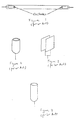
- the electrodes 3 may themselves be substantially of a cylindrical shape as for example as shown in Figure 7, or consist of parallel plates as for example shown in Figure 8, or may be rod-shaped as for example shown in Figure 9.
- Sputtering is worst when the lamp starts. But it seems that sputtering will continue to occur (though to a lesser degree) after starting. While electron bombardment is the cause of sputtering, heating of the electrode may increase sputtering (the heat causes the atoms to become more energetic and to break the bond more easily).
- a tubular electrode (Fig.7), the rim of the electrode facing the ionization region has the worst sputtering because that is the main area of electron bombardment and has a small area.
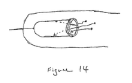
- an electron shield or electrically insulating cap covers the rim, the fact that the cap is insulating causes the electrons not to bombard the cap but to bombard the other conducting portions of the electrode, such as the inner wall of the tubular electrode as seen in Fig. 14. The area of bombardment in that case is bigger and so sputtering is less serious.
- Fig. 12 shows where the sputtered metal (from bombardment of the inner wall of the electrode) is deposited according to a preferred embodiment of the present invention utilising the cap. This figure shows that with the cap in place, sputtering does still occur but the depositing starts from the edge of the electrode. This indicates the sputtered metal came from the inner wall of the tubular electrode.
- Fig. 13 shows more serious sputtering and where the sputtered metal (from bombardment of the rim of the electrode) is deposited. Note the location of the region covered by the sputtered metal is different from that shown in Fig. 12 and is on both sides of the edge of the electrode.
- the edges of the parallel plates facing the ionization region have the worst sputtering because the areas are small.
- the rim at the end thereof is a sharp edge and has the worst sputtering.
- sputtering is relatively serious where there is a sharp point.
- the disc shaped end of a rod shaped electrode facing the ionization region would also likely have serious sputtering - relatively small area and possibly sharp points on a not completely smooth surface.
- Figures 7 and 8 show the cap in 'situ.
- the cap is made from high heat resistant material and is preferably of a thickness sufficient to allow it to absorb a significant amount of heat. It is placed so as to face the main direction of movement of the electrons and to overlay the electrode at such regions otherwise significantly exposed to bombardment thereby.
- the ionisation region it is to be understood to be that region of the bulb or tube where the most significant proportion of ionisation will be induced by the electrodes. This region is normally the largest uninterrupted volume region and where, for example, a glass tube is used, the ionisation region is a substantial portion of the tube between its distal ends. Those regions which may be considered as non ionised regions are normally those regions of the tube or bulb which are behind the electrodes. In other words in one example, a non ionised region may be anywhere within the bulb or tube not intermediate of the two electrodes.
- the electrodes of a thin wall cylindrical nature as for example shown in Figure 7 or of a thin wall planar nature as shown in Figure 8 can lead to significant sputtering problems because of the small main area onto which electrons can be bombarded.
- solid rod electrodes as for example shown in Figures 9a and 9b can also benefit from the provision of a protective cap as its end surface is lateral (or at substantially right angle) to the main elongate direction of the glass tube hence thereby exposing such a surface to maximum impact forces by the electrons.
- Figures 8a and 8b illustrate one form of a particular electrode arrangement for a CCFL.
- a pair of substantially parallel (usually metal) plates 3 are provided to be positioned proximate to each other and positioned in one region adjacent the main ionisation region within the lighting enclosure. Both parallel plates 3 are supplied by energy from a common electrical source.
- the planes of the electrodes where the tube is of an elongate nature are substantially parallel to the elongate direction of the tube.
- Figures 8a and 8b show both of the parallel plates being covered by caps, covering only one of the parallel plates 3 by a cap would still achieve reduced sputtering.
- Figures 9a and 9b show possible caps for the rod-shaped electrode.
- Figure 9c illustrates a cap which consists of an annular ring of a sufficient size to overlay at least the perimeter surfaces of the rod-shaped electrode.
- the sealed lighting tube 1 is an elongate substantially cylindrical member, it is envisaged that as an alternative a bulb shaped like enclosure may also be provided.
- the cap is provided to that end of the electrode which is proximate most to the ionisation region within the tube, it is envisaged that in a more bulbous version, it will be that portion of the electrode which likewise is exposed to the ionisation region and where such an electrode is most likely to be subjected to high quantities of bombardment.
- the electrode is provided proximate more towards one end of the sealed lighting enclosure (whether it is a tube or a bulb); the main ionisation region is provided in a region of such an enclosure away from the location where the electrode is provided.
- the internal diameter of the glass tube is approximately 1 to 8 mm so the outside diameter of the tubular, cylindrical or rod-shaped electrode is approximately from 0.7 to 7 mm.
- the cap may be removably attached to the electrode by simply placing the cap over the tip of the electrode.
- the cap can be taken off since the cap is not fired with the electrode and hence is a separate item that can be subsequently attached after the electrode has been created.
- the electrode and the cap may be fired so that the cap is permanently attached to the electrode.
- the electrode preferably has holes or recesses on its surface and the cap will as a result hold onto the electrode firmly because of the increased area of contact.
- cap has been described for a number of different electrodes it is important only that portions of the electrode that are vulnerable to sputtering be covered. Accordingly any shape of cap or cover is possible. Particularly vulnerable areas include sharp edges or points. The portion of an electrode with a relatively small area facing the ionisation region is also vulnerable.
- the photographs 12 and 13 show the effect of adding a cap.
- the lamps are shown after 800 hours use.
- Figure 13 illustrates the electrode without a cap with a significantly less translucent region 10 (or sputtering region)
- Figure 12 illustrates the electrode 3 with a cap 5 and a less significant (smaller or more translucent) sputtering region 10a.
- the lifetime of a CCFL may be increased from 2 to 5 times.
- reduced or no sputtering means the absence of the secondary conducting path, therefore the illumination efficiency can be increased from 2 to 5%.
- an embodiment of the invention refers to a cold-cathode fluorescent lamp, comprising a sealed lighting enclosure provided with a phosphor coating on at least part of an inner surface thereof the lighting enclosure.
- An electrode is provided juxtaposed a region of the inner surface of the lighting tube, the electrode energisable from an external source of energy via an electric lead supporting the electrode, and positioned adjacent the main ionisation region within the lighting enclosure.
- the phosphor is to be excited by radiation to be generated inside the lighting tube by electric discharge from the electrode to provide visible radiation.
- At least part of the surface(s) of that portion of the electrode proximal most to the ionisation region are overlaid by a cap made from a high heat resistive and non conductive material.
Landscapes
- Discharge Lamp (AREA)
- Vessels And Coating Films For Discharge Lamps (AREA)
Applications Claiming Priority (2)
| Application Number | Priority Date | Filing Date | Title |
|---|---|---|---|
| US10/662,910 US6963164B2 (en) | 2003-09-15 | 2003-09-15 | Cold cathode fluorescent lamps |
| US662910 | 2003-09-15 |
Publications (2)
| Publication Number | Publication Date |
|---|---|
| EP1517358A2 true EP1517358A2 (fr) | 2005-03-23 |
| EP1517358A3 EP1517358A3 (fr) | 2006-10-04 |
Family
ID=34194718
Family Applications (1)
| Application Number | Title | Priority Date | Filing Date |
|---|---|---|---|
| EP04014138A Withdrawn EP1517358A3 (fr) | 2003-09-15 | 2004-06-16 | Améliorations dans des lampes fluorescentes à cathode froide |
Country Status (7)
| Country | Link |
|---|---|
| US (1) | US6963164B2 (fr) |
| EP (1) | EP1517358A3 (fr) |
| JP (2) | JP2007506228A (fr) |
| KR (2) | KR20060121918A (fr) |
| CN (2) | CN2751435Y (fr) |
| TW (1) | TWM273815U (fr) |
| WO (1) | WO2005027181A1 (fr) |
Families Citing this family (8)
| Publication number | Priority date | Publication date | Assignee | Title |
|---|---|---|---|---|
| JP2005209382A (ja) * | 2004-01-20 | 2005-08-04 | Sony Corp | 放電灯および放電灯用電極 |
| TWI301902B (en) * | 2005-01-13 | 2008-10-11 | Au Optronics Corp | Light source and backlight module utilizing the same |
| US7893617B2 (en) * | 2006-03-01 | 2011-02-22 | General Electric Company | Metal electrodes for electric plasma discharge devices |
| CN100446170C (zh) * | 2006-04-05 | 2008-12-24 | 东南大学 | 一种陶瓷冷阴极荧光灯阴极 |
| WO2008011810A1 (fr) | 2006-07-19 | 2008-01-31 | Shichao Ge | Lampe d'éclairage fluorescente à cathode froide et à flux lumineux intense |
| JP5273334B2 (ja) * | 2007-02-26 | 2013-08-28 | 株式会社ジャパンディスプレイ | 冷陰極蛍光管及びこの冷陰極蛍光管を用いた液晶表示装置 |
| CN101796608B (zh) * | 2007-09-07 | 2012-09-05 | 夏普株式会社 | 荧光管、显示装置用照明装置、显示装置 |
| US9030659B2 (en) | 2013-07-23 | 2015-05-12 | Massachusetts Institute Of Technology | Spark-induced breakdown spectroscopy electrode assembly |
Family Cites Families (23)
| Publication number | Priority date | Publication date | Assignee | Title |
|---|---|---|---|---|
| US1984482A (en) * | 1931-01-13 | 1934-12-18 | Gen Electric | Gaseous electric discharge device |
| GB557516A (en) | 1941-02-21 | 1943-11-24 | British Thomson Houston Co Ltd | Improvements in and relating to gas filled electric discharge devices and circuits therefor |
| US2375808A (en) * | 1943-02-16 | 1945-05-15 | Samuel C Miller | Electrode for luminous tubes |
| GB590048A (en) | 1944-04-27 | 1947-07-07 | Lumalampan Ab | Electric discharge tube |
| US3778662A (en) * | 1972-10-31 | 1973-12-11 | Gen Electric | High intensity fluorescent lamp radiating ionic radiation within the range of 1,600{14 2,300 a.u. |
| JPS57122441A (en) | 1981-01-22 | 1982-07-30 | Toppan Printing Co Ltd | Screen for gravure and its production |
| US4461970A (en) | 1981-11-25 | 1984-07-24 | General Electric Company | Shielded hollow cathode electrode for fluorescent lamp |
| JPH04137429A (ja) * | 1990-09-28 | 1992-05-12 | Toshiba Lighting & Technol Corp | 冷陰極蛍光ランプ |
| JP2717770B2 (ja) * | 1994-11-04 | 1998-02-25 | 協和電子株式会社 | ネオン管の電極及びネオン管 |
| JPH08321279A (ja) | 1995-05-24 | 1996-12-03 | Harrison Denki Kk | 冷陰極低圧放電灯 |
| US5880559A (en) * | 1996-06-01 | 1999-03-09 | Smiths Industries Public Limited Company | Electrodes and lamps |
| JPH11154489A (ja) | 1997-09-20 | 1999-06-08 | New Japan Radio Co Ltd | 放電管用陰極、該陰極の製造方法およびアークランプ |
| JPH11213945A (ja) * | 1998-01-28 | 1999-08-06 | Kyowa Denshi Kk | ネオン管用電極及びネオン管 |
| US6173351B1 (en) | 1998-06-15 | 2001-01-09 | Sun Microsystems, Inc. | Multi-processor system bridge |
| JP2001015063A (ja) | 1999-06-30 | 2001-01-19 | Toshiba Lighting & Technology Corp | 蛍光ランプ、蛍光ランプ装置およびバックライト装置 |
| US6337543B1 (en) | 1999-12-20 | 2002-01-08 | Gl Displays, Inc. | High power cold cathode gas discharge lamp using sub-electrode structures |
| JP2001118497A (ja) | 1999-10-18 | 2001-04-27 | Stanley Electric Co Ltd | 酸化物放電電極の製造方法及び該酸化物放電電極を具備する冷陰極蛍光ランプ |
| JP2001283771A (ja) * | 2000-03-30 | 2001-10-12 | Toshiba Lighting & Technology Corp | 希ガス放電管 |
| JP2001351572A (ja) | 2000-06-09 | 2001-12-21 | Stanley Electric Co Ltd | 冷陰極蛍光灯 |
| JP3760094B2 (ja) | 2000-12-07 | 2006-03-29 | サンケン電気株式会社 | 冷陰極放電管用電極及びその製法 |
| JP2002289138A (ja) | 2001-03-28 | 2002-10-04 | Matsushita Electric Ind Co Ltd | 冷陰極蛍光ランプ |
| JP2002289139A (ja) * | 2001-03-28 | 2002-10-04 | Matsushita Electric Ind Co Ltd | 冷陰極放電ランプ |
| JP2002358922A (ja) * | 2001-05-31 | 2002-12-13 | Sanken Electric Co Ltd | 冷陰極放電管及びその製法 |
-
2003
- 2003-09-15 US US10/662,910 patent/US6963164B2/en not_active Expired - Fee Related
-
2004
- 2004-06-11 CN CNU2004200668448U patent/CN2751435Y/zh not_active Expired - Fee Related
- 2004-06-15 TW TW093209411U patent/TWM273815U/zh not_active IP Right Cessation
- 2004-06-16 EP EP04014138A patent/EP1517358A3/fr not_active Withdrawn
- 2004-07-30 CN CNA2004800265204A patent/CN1853256A/zh active Pending
- 2004-07-30 WO PCT/NZ2004/000169 patent/WO2005027181A1/fr not_active Ceased
- 2004-07-30 JP JP2006526039A patent/JP2007506228A/ja active Pending
- 2004-07-30 KR KR1020067006976A patent/KR20060121918A/ko not_active Withdrawn
- 2004-08-12 JP JP2004004858U patent/JP3107190U/ja not_active Expired - Fee Related
- 2004-08-26 KR KR20-2004-0024420U patent/KR200369059Y1/ko not_active Expired - Fee Related
Also Published As
| Publication number | Publication date |
|---|---|
| KR20060121918A (ko) | 2006-11-29 |
| US20050057143A1 (en) | 2005-03-17 |
| CN1853256A (zh) | 2006-10-25 |
| KR200369059Y1 (ko) | 2004-12-04 |
| JP2007506228A (ja) | 2007-03-15 |
| TWM273815U (en) | 2005-08-21 |
| US6963164B2 (en) | 2005-11-08 |
| WO2005027181A1 (fr) | 2005-03-24 |
| JP3107190U (ja) | 2005-01-27 |
| CN2751435Y (zh) | 2006-01-11 |
| EP1517358A3 (fr) | 2006-10-04 |
Similar Documents
| Publication | Publication Date | Title |
|---|---|---|
| EP1298695B1 (fr) | Tube à décharge gazeuse et dispositif d'affichage utilisant celui-ci | |
| EP0767485B1 (fr) | Lampe fluorescente sans électrodes | |
| US4882520A (en) | Rare gas arc lamp having hot cathode | |
| US6800997B2 (en) | Cold-cathode fluorescent lamp | |
| US6963164B2 (en) | Cold cathode fluorescent lamps | |
| US6465955B1 (en) | Gas discharge lamp | |
| US7717766B2 (en) | Fluorescent lamp and method of manufacturing fluorescent lamp | |
| US20040135489A1 (en) | Fluorescent lamp | |
| US5698951A (en) | Electrodeless discharge lamp and device for increasing the lamp's luminous development | |
| HK1074697A (en) | Improvements to cold cathode fluorescent lamps | |
| TWI330381B (fr) | ||
| US6097152A (en) | Composite discharge lamp having center, arc electrodes coated for electron emission | |
| KR100943873B1 (ko) | 열음극 형광 램프 | |
| JP4683549B2 (ja) | 外部電極放電ランプ | |
| JP2002025499A (ja) | 冷陰極蛍光ランプ | |
| JPH04274156A (ja) | 冷陰極放電灯 | |
| JPH07296775A (ja) | 平面型蛍光ランプ | |
| JP3873484B2 (ja) | 低圧放電ランプおよび照明装置 | |
| JP4258368B2 (ja) | 無電極放電ランプ | |
| JP2001006608A (ja) | 希ガス放電ランプ及び希ガス放電ランプの製造方法及び希ガス放電ランプを用いた装置 | |
| JPH03226956A (ja) | 蛍光ランプ | |
| JPH10283989A (ja) | 冷陰極放電灯 | |
| JP2005026196A (ja) | 冷陰極蛍光ランプ |
Legal Events
| Date | Code | Title | Description |
|---|---|---|---|
| PUAI | Public reference made under article 153(3) epc to a published international application that has entered the european phase |
Free format text: ORIGINAL CODE: 0009012 |
|
| AK | Designated contracting states |
Kind code of ref document: A2 Designated state(s): AT BE BG CH CY CZ DE DK EE ES FI FR GB GR HU IE IT LI LU MC NL PL PT RO SE SI SK TR |
|
| AX | Request for extension of the european patent |
Extension state: AL HR LT LV MK |
|
| REG | Reference to a national code |
Ref country code: HK Ref legal event code: DE Ref document number: 1074697 Country of ref document: HK |
|
| PUAL | Search report despatched |
Free format text: ORIGINAL CODE: 0009013 |
|
| AK | Designated contracting states |
Kind code of ref document: A3 Designated state(s): AT BE BG CH CY CZ DE DK EE ES FI FR GB GR HU IE IT LI LU MC NL PL PT RO SE SI SK TR |
|
| AX | Request for extension of the european patent |
Extension state: AL HR LT LV MK |
|
| RIC1 | Information provided on ipc code assigned before grant |
Ipc: H01J 61/70 20060101ALI20060830BHEP Ipc: H01J 61/09 20060101ALI20060830BHEP Ipc: H01J 1/30 20060101ALI20060830BHEP Ipc: H01J 61/067 20060101AFI20050131BHEP |
|
| 17P | Request for examination filed |
Effective date: 20070404 |
|
| 17Q | First examination report despatched |
Effective date: 20070510 |
|
| AKX | Designation fees paid |
Designated state(s): AT BE BG CH CY CZ DE DK EE ES FI FR GB GR HU IE IT LI LU MC NL PL PT RO SE SI SK TR |
|
| STAA | Information on the status of an ep patent application or granted ep patent |
Free format text: STATUS: THE APPLICATION IS DEEMED TO BE WITHDRAWN |
|
| 18D | Application deemed to be withdrawn |
Effective date: 20070921 |
|
| REG | Reference to a national code |
Ref country code: HK Ref legal event code: WD Ref document number: 1074697 Country of ref document: HK |