EP1517340B1 - Strahlungsbildwandler und Verfahren zu seiner Herstellung - Google Patents
Strahlungsbildwandler und Verfahren zu seiner Herstellung Download PDFInfo
- Publication number
- EP1517340B1 EP1517340B1 EP04021311A EP04021311A EP1517340B1 EP 1517340 B1 EP1517340 B1 EP 1517340B1 EP 04021311 A EP04021311 A EP 04021311A EP 04021311 A EP04021311 A EP 04021311A EP 1517340 B1 EP1517340 B1 EP 1517340B1
- Authority
- EP
- European Patent Office
- Prior art keywords
- image conversion
- radiographic image
- conversion panel
- support
- stimulable phosphor
- Prior art date
- Legal status (The legal status is an assumption and is not a legal conclusion. Google has not performed a legal analysis and makes no representation as to the accuracy of the status listed.)
- Expired - Lifetime
Links
Images

Classifications
-
- G—PHYSICS
- G21—NUCLEAR PHYSICS; NUCLEAR ENGINEERING
- G21K—HANDLING OF PARTICLES OR IONISING RADIATION NOT OTHERWISE PROVIDED FOR; IRRADIATION DEVICES; GAMMA RAY OR X-RAY MICROSCOPES
- G21K4/00—Conversion screens for the conversion of the spatial distribution of X-rays or particle radiation into visible images, e.g. fluoroscopic screens
-
- C—CHEMISTRY; METALLURGY
- C09—DYES; PAINTS; POLISHES; NATURAL RESINS; ADHESIVES; COMPOSITIONS NOT OTHERWISE PROVIDED FOR; APPLICATIONS OF MATERIALS NOT OTHERWISE PROVIDED FOR
- C09K—MATERIALS FOR MISCELLANEOUS APPLICATIONS, NOT PROVIDED FOR ELSEWHERE
- C09K11/00—Luminescent materials, e.g. electroluminescent or chemiluminescent
- C09K11/08—Luminescent materials, e.g. electroluminescent or chemiluminescent containing inorganic luminescent materials
- C09K11/77—Luminescent materials, e.g. electroluminescent or chemiluminescent containing inorganic luminescent materials containing rare earth metals
- C09K11/7728—Luminescent materials, e.g. electroluminescent or chemiluminescent containing inorganic luminescent materials containing rare earth metals containing europium
- C09K11/7732—Halogenides
- C09K11/7733—Halogenides with alkali or alkaline earth metals
-
- G—PHYSICS
- G03—PHOTOGRAPHY; CINEMATOGRAPHY; ANALOGOUS TECHNIQUES USING WAVES OTHER THAN OPTICAL WAVES; ELECTROGRAPHY; HOLOGRAPHY
- G03C—PHOTOSENSITIVE MATERIALS FOR PHOTOGRAPHIC PURPOSES; PHOTOGRAPHIC PROCESSES, e.g. CINE, X-RAY, COLOUR, STEREO-PHOTOGRAPHIC PROCESSES; AUXILIARY PROCESSES IN PHOTOGRAPHY
- G03C5/00—Photographic processes or agents therefor; Regeneration of such processing agents
- G03C5/16—X-ray, infrared, or ultraviolet ray processes
- G03C5/17—X-ray, infrared, or ultraviolet ray processes using screens to intensify X-ray images
-
- G—PHYSICS
- G21—NUCLEAR PHYSICS; NUCLEAR ENGINEERING
- G21K—HANDLING OF PARTICLES OR IONISING RADIATION NOT OTHERWISE PROVIDED FOR; IRRADIATION DEVICES; GAMMA RAY OR X-RAY MICROSCOPES
- G21K4/00—Conversion screens for the conversion of the spatial distribution of X-rays or particle radiation into visible images, e.g. fluoroscopic screens
- G21K2004/06—Conversion screens for the conversion of the spatial distribution of X-rays or particle radiation into visible images, e.g. fluoroscopic screens with a phosphor layer
Definitions
- the present invention relates to a radiographic image conversion panel, in which a stimulable phosphor substance layer is formed on a support by means of a vapor-accumulating method, and a manufacturing method of the radiographic image conversion panel.
- a radiographic image conversion panel in which a stimulable phosphor substance is formed on a support is utilized for recording radiographic images.
- a portion of the radiation transmitted through a subject for image taking is absorbed by a stimulable phosphor substance layer formed on a radiographic image conversion panel.
- excitation light such as laser light is irradiated on the stimulable phosphor layer to make radiation energy accumulated in a stimulable phosphor layer emit as phosphor light which is detected, resulting in formation of images.
- a method to form a stimulable phosphor substance layer on such a radiographic image conversion panel there is known a method in which a binder is mixed with a stimulable phosphor substance and the resulting mixture is coated on a support.
- this method may lower the purity of a stimulable phosphor substance causing decreasing the efficiency of excitation light penetration and stimulated emission, and resulting in deterioration of image qualities such as sharpness and granularity of recorded images. Therefore, a method to form a stimulable phosphor substance layer by means of a vapor-accumulating method (or a gas phase accumulation method) has been developed to improve image quality of recorded images (for example, refer to a Patent Literature 1).
- a stimulable phosphor substance layer contains only a stimulable phosphor substance without a binder, the efficiency of excitation light penetration and stimulated emission is improved resulting in obtaining images of high quality.
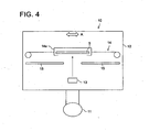
- a stimulable phosphor substance is accumulated on a support by means of evaporation or sputtering, and, for example, evaporation system 10 shown in Fig. 4 has been utilized in case of an evaporation method.
- Evaporation system 10 contains vacuum chamber 12 equipped with vacuum pump 11, vapor source 13, and support transporting mechanism 14 which supports support S as well as transports support S back and forth against vapor source 13 in the horizontal direction in said vacuum chamber 12. Further, in this evaporation system 10, slit plate 15 is installed between vapor source 13 and support S to restrict evaporation onto support S, while transferring support S.
- a stimulable phosphor substance layer can be formed nearly uniformly onto all over support S by evaporating vapor of a stimulable phosphor substance which has passed through slit 15 from vapor source onto support S.
- a radiographic image conversion panel utilized in this radiographic image recording and reproducing method contains a support and a stimulable phosphor substance layer provided on the support.
- a stimulable phosphor substance utilized is one which comprises an alkali halide such as CsBr as a mother substance being activated with Eu, and it is considered that an X-ray conversion efficiency can be improved, which has been impossible heretofore, specifically by employing Eu as an activator.
- the concentration of an activator there is a correlation between the concentration of an activator and the luminance, and the higher is the concentration of an activator, the higher is the sensitivity.
- the sensitivity is saturated at the limiting concentration of an activator at which excitation light can penetrate into the phosphor substance layer and make the accumulated energy to release at the time of reading. Therefore, the more non-uniform is the concentration of an activator, the more uneven is the sensitivity.
- EP-A 1 288 680 discloses a scintillator panel for a radiation detection device comprising an alkali halogenide phosphor, in particular Csl, Nal and CsBr doped with TI and Na. The document does not refer to a density variation coefficient.
- US 2002/0192501 A1 discloses a phosphor thin film comprising a matrix material and a luminescent centre.
- the matrix material is an oxysulfide having a specific atomic ratio of the oxygen to the total of oxygen and sulphur.
- a stimulable phosphor substance layer absorbs radiation and accumulate the energy
- the thicker is the layer thickness of a stimulable phosphor substance layer, the higher becomes the sensitivity, and the sensitivity is saturated at a certain layer thickness at which radiation energy accumulated in a stimulable phosphor substance is able to be released.
- vapor generated from vapor source 13 may proceed irregularly from slit 15 to the side of support S to cause unevenness in the layer thickness of a stimulable phosphor substance layer. Therefore, a higher sensitive portion and a lower sensitive portion are generated locally on a panel resulting in sensitivity unevenness.
- An object of the invention is to provide a radiographic image conversion panel having a decreased bending property and a decreased sensitivity unevenness.
- An embodiment of the present invention includes a radiographic image conversion panel containing a substrate having thereon a phosphor layer formed by a vapor-accumulating method as defined in claim 1.
- An embodiment of the present invention includes a radiographic image conversion panel containing a substrate having thereon a phosphor layer formed by a vapor-accumulating method as defined in claim 1.
- the phosphor contains ; a stimulable phosphor substance, MlX ⁇ aM2X' 2 bM3X'' 3 : eA, represented by general formula (1) as a starting material of a phosphor substance layer.
- a phosphor substance is evaporated on a support while the support is rotated, it is possible to form a phosphor layer on a support so as to have more uniform layer thickness of the phosphor substance as well as a concentric circular layer thickness distribution from the center of the phosphor substance layer. Therefore, it is possible to reduce layer thickness distribution or the coefficient of variation of the phosphor substance layer as well as to compensate stress generated on a panel, resulting in manufacturing a radiographic image conversion panel having minimum sensitivity unevenness and little bending.
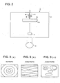
- Fig. 1 shows radiographic image conversion panel P applied in the present invention.
- Radiographic image conversion panel P contains a support S and stimulable phosphor substance layer R, in which prismatic crystals of a stimulable phosphor substance is formed by a vapor-accumulating method, on said support S, and a protective layer to protect stimulable phosphor substance layer R (being not shown in the drawing) is appropriately provided on this stimulable phosphor substance layer R.
- a material of support S can be arbitrarily selected from commonly known materials as a support of a conventional radiographic image conversion panel, however, a support in the case of forming a phosphor substance layer by a vapor-accumulating method are preferably quartz glass, a metal sheet comprising such as aluminum, iron, tin or chromium, a carbon fiber reinforced resin sheet comprising a sheet of carbon fibers which are oriented in one direction and contain heat resistive resin.
- support S is preferably provided with resin layer Sa which makes the support surface smooth.
- Resin layer Sa preferably contains a compound such as polyimide, polyethylene terephthalate, paraffin and graphite, and the layer thickness is preferably approximately 5 - 50 ⁇ m. This resin layer may be provided either on the front or the backside surface of support S, or may be provided on the both surfaces.
- a means to provide resin layer Sa on support S includes a lamination method and a coating method.
- a lamination method is performed by use of heat rollers or pressure rollers, and preferable conditions are heating at approximately 80 - 150 °C, pressing at 4.90 - 2.94 x 10² (N/cm) and a transport rate of 0.1 - 2.0 (m/sec).
- M1 represents at least one type of an alkali earth metal atom selected from each atom of Li, Na, K, Rb and Cs, among them preferably at least one type of atom selected from each atom of Rb and Cs and more preferably Cs atom.
- M2 represents at least one type of a divalent metal atom selected from each atom of Be, Mg, Ca, Sr, Ba, Zn, Cd, Cu and Ni, and among them preferably utilized is an atom selected from Be, Mg, Ca, Sr and Ba.
- M3 represents at least one type of a trivalent metal atom selected from each atom of Sc, Y, La, Ce, Pr, Nd, Pm, Eu, Gd, Tb, Dy, Ho, Er, Tm, Yb, Lu, Al, Ga and In, and among them preferably utilized is an atom selected from Y, Ce, Sm, Eu, Al, La, Gd, Lu, Ga and In.
- A represents at least one type of a metal atom selected from each atom of Eu, Tb, In, Ce, Tm, Dy, Pr, Ho, Nd, Yb, Er, Gd, Lu, Sm, Y, Tl, Na, Ag, Cu and Mg, and among them preferably Eu atom.
- X, X' and X'' represent at least one type of a halogen atom selected from F, Cl, Br and I, preferably one type of a halogen atom selected from F, Cl and Br and more preferably Br atom, with respect to emission strength improvement of stimulated emission of stimulable phosphor substance.
- a, b and e each are values in ranges of 0 ⁇ a ⁇ 0.5, 0 ⁇ b ⁇ 0.5 and 0 ⁇ e ⁇ 1.0, respectively, and preferably 0 ⁇ b ⁇ 10 -2 .
- Stimulable phosphor substances represented by general formula (1) of the present invention are manufactured, for example, by the following method.
- Starting material (e) compounds containing a metal atom selected from Eu, Tb, In, Ce, Tm, Dy, Pr, Ho, Nd, Yb, Er, Gd, Lu, Sm, Y, Tl, Na, Ag Cu and Mg.
- Phosphor substance starting materials (a), (b) and (e), which are weighed so as to be the values in the ranges of a, b and e of general formula (1), are dissolved in pure water.
- the starting materials may be sufficiently mixed by use of such as a mortar, a ball mill and a mixer mill.
- the mixture of stating materials obtained by evaporation of water was charged into a heat-resistant vessel such as a quartz crucible or an alumina crucible and is burned in an electric furnace.
- the burning temperature is preferably 500 - 1000 °C.
- the burning time differs depending on such as a charging amount of starting materials and a burning temperature, however, is preferably 0.5 - 6 hours.
- the burning atmosphere is preferably a nitrogen gas atmosphere containing a small amount of a hydrogen gas, a weakly reducing atmosphere such as a carbon gas atmosphere containing a small amount of carbon monoxide, neutral atmospheres such as a nitrogen atmosphere and an argon atmosphere, or a weakly oxidizing atmosphere containing a small amount of an oxygen gas.
- the burned substance in the case that the burned substance is taken out of an electric furnace and ground after having been once burned in the above burning condition, thereafter, the burned substance powder is charged into a heat-resistant vessel and placed in an electric furnace to be burned again in the same condition as the above; a desired stimulable emission luminance of a stimulable phosphor substance can be obtained also by being taken out of an electric furnace followed by being spontaneously cooled in air, however, the burned substance may be cooled in a weakly reducing atmosphere or a neutral atmosphere which is same as that during burning.
- a burned substance is transferred from a heating section to a cooling section within a furnace and rapidly cooled in a weakly oxidizing atmosphere because a stimulable emission luminance of the obtained stimulable phosphor substance can be further increased.
- the stimulable phosphor substance thus manufactured is evaporated on support S by means of a vapor-accumulating method resulting in formation of stimulable phosphor substance layer R.
- a vapor-accumulating method evaporation method, a sputtering method, a CVD (Chemical Vapor Deposition) method, an ion-plating method and other methods can be employed and a evaporation method is specifically preferable in the present invention.
- a vapor-accumulating method evaporation method, a sputtering method, a CVD (Chemical Vapor Deposition) method, an ion-plating method and other methods
- a evaporation method is specifically preferable in the present invention.
- evaporation method evaporation method, a sputtering method, a CVD (Chemical Vapor Deposition) method, an ion-plating method and other methods
- a evaporation method is specifically preferable in the present invention.
- evaporation system 1 shown in Fig. 2 is employed.
- evaporation system 1 contains vacuum chamber 2, vacuum pump 3 which performs evacuation and air introduction of the vacuum chamber 2, vapor source 4 which is arranged in vacuum chamber 2 and evaporates a vapor on support S, and support rotating mechanism 5 which holds support S and rotates support S against vapor source 4.
- Vapor source 4 may contain an alumina crucible wound with a heater or a heater comprising a boat or a high melting temperature metal, to accommodate a stimulable phosphor substance to be heated by a resistance heating method.
- a method to heat a stimulable phosphor substance may be a heating by means of electron beam or a heating by means of high frequency induction in addition to a resistance heating method, however, a resistance heating is preferred in the present invention with respect to a relatively simple constitution and easy handling as well as being applicable easily and to grate many substances.
- vapor source 4 may be a molecular beam source by means of a molecular beam epitaxial method.
- Support rotating mechanism 5 contains, for example, support holder 5a to hold support S, rotation axis 5b to rotate said support holder 5a and motor (being not shown in the figure) which is arranged outside vacuum chamber 2 and works as a driving source of rotating axis 5b.
- support holder 5a is preferably equipped with a heater (being not shown in the figure) to heat support S.
- Heating support S makes it possible to detach and eliminate absorbed substances from the surface of support S, resulting in generation of an impurity layer between the surface of support S and stimulable phosphor substance layer R, or to enhance adhesion and adjust the layer properties.
- a shutter (being not shown in the figure) may be provided between support S and vapor source 4 to shield the space from vapor source to support S.
- the shutter can prevent substances other than the evaporation objective, which have adhered on the surface of a stimulable phosphor substance, from adhering on a support by being evaporated at the initial stage of evaporation.
- support S is held on support holder 5a.
- the inside of vacuum chamber 2 is evacuated.
- support holder 5a is rotated against the vapor source by use of support rotating mechanism 5, and a stimulable phosphor substance is evaporated from heated vapor source 4 when a vacuum degree inside vacuum chamber 2 reaches a vacuum degree possible for evaporation resulting in growth of a desired thickness of the stimulable phosphor substance on the surface of support S.
- the distance between support S and vapor source 4 is adjusted between 100 - 1500 mm.
- stimulable phosphor substance layer R it is possible to perform evaporation dividing into plural times to form stimulable phosphor substance layer R.
- a stimulable phosphor substance layer simultaneously with synthesizing an objective stimulable phosphor substance on support S by coevaporation by utilizing a plural number of resistance heaters or electron beams.
- materials to be subjected to evaporation may be appropriately cooled or heated at the time of evaporation.
- a stimulable phosphor substance layer may be subjected to a heat treatment after finishing evaporation.
- applied may be a reactive evaporation in which evaporation is performed by appropriately introducing a gas such as O 2 and H 2 .
- the thickness of formed stimulable phosphor substance layer R differs depending on application purposes of a radiographic image conversion panel and types of a stimulable phosphor substance, however, is in a range of 100 - 800 ⁇ m, with respect to achieving the effects of the present invention.
- the temperature of support S, on which stimulable phosphor substance layer R is formed is preferably set at room temperature (RT) to 300 °C and more preferably at 50 - 200 °C.
- a protective layer may be appropriately provided so as to cover stimulable phosphor substance layer R after which has been formed in the aforesaid manner.
- a protective layer may be formed by directly coating a protective layer coating solution on the surface of stimulable phosphor substance layer R, or by adhering a protective layer separately prepared in advance onto stimulable phosphor substance layer R.
- a transparent glass substrate may be employed as a protective layer.
- the protective layer inorganic substances such as SiC, SiO 2 , SiN and Al 2 O 3 may be accumulated by an evaporation method or a sputtering method.
- the thickness of these protective layer is preferably 0.1 - 2000 ⁇ m.
- a plural number of carbon fiber reinforced resin sheets being accumulated are heated at 130 °C and pressed at a pressure of 100 N/cm to prepare support S.
- CsBr:0.0002 Eu as a stimulable phosphor substance was manufactured, which was evaporated on support S to form stimulable phosphor substance layer R, resulting in manufacture of radiographic image conversion panels of examples A - D and comparative examples 1 and 2 described below.
- Evaporation in examples A - D was performed by use of evaporation system 1 shown in Fig. 2
- evaporation in comparative examples 1 and 2 was performed by use of evaporation system 10 shown in Fig. 4 .
- the above-described stimulable phosphor substance (CsBr:0.0002Eu) as an evaporation material was filled into a resistance heating crucible inside vapor source 4, and support S was placed at support holder 5a.
- the temperature of support S was kept at 100 °C while support S was rotated at a rate of 10 rpm by support rotating mechanism 5. Then, the stimulable phosphor substance was evaporated onto support S by heating the resistance heating crucible to form a stimulable phosphor substance layer, and evaporation was finished when the thickness of the stimulable phosphor layer reached approximately 500 ⁇ m. Successively, the stimulable phosphor substance layer was taken into a protective layer bag under dry air resulting in preparation of a radiographic image conversion panel containing a stimulable phosphor substance layer being sealed.
- the above-described stimulable phosphor substance (CsBr:0.0002Eu) as an evaporation material was filled into a resistance heating crucible inside vapor source 13 of evaporation system 10 (refer to Fig. 4 ), and support S was placed at support holder 14a.
- the distance between support S and vapor source 13 was adjusted to 400 mm.
- the temperature of support S was kept at 100 °C while support S was transferred back and forth along direction A by support transfer mechanism 14. Then, the stimulable phosphor substance was evaporated onto support S by heating the resistance heating crucible to form a stimulable phosphor substance layer, and evaporation was finished when the thickness of the stimulable phosphor layer reached approximately 500 ⁇ m. Successively, the stimulable phosphor substance layer was taken into a protective layer bag under dry air resulting in preparation of a radiographic image conversion panel containing a stimulable phosphor substance layer being sealed. [Comparative Example 2]
- layer thicknesses at 30 measuring points which were arranged in rows at equal intervals on a radiographic image conversion panel were measured, and measured points, where the layer thicknesses are nearly same, were connected by a curved line (this curved line is called as an iso-thickness line) to judge whether the layer thickness distribution is isotropic or anisotropic.
- a layer thickness distribution is isotropic means that the layer thickness is nearly uniform at positions of an equal distance from the center of a panel and has no distribution depending on the directions from the center.
- a layer thickness distribution is anisotropic means that the layer thickness has a distribution depending on the directions from the center of a panel.
- Fig. 3 (a) it is judged to be isotropic when the iso-thickness lines spread homo-centrically (including a normal circle and an ellipse) from the center of a panel, as is shown in Fig. 3 (a)
- Fig. 3 (b) it is judged to be anisotropic when the iso-thickhess lines stand in a row in one direction as is shown in Fig. 3 (b) or several homo-centrically distributed iso-thickness lines exist locally as is shown in Fig. 3 (c) .
- the layer thickness distribution is an index value to represent a degree of the layer thickness distribution of a stimulable phosphor substance in a stimulable phosphor substance layer.
- the layer thickness distribution was calculated according to following equation (2) by measuring the maximum layer thickness D max and the minimum layer thickness D min in a stimulable phosphor substance layer.
- Layer thickness distribution D max - D min / ( D max + D min ) ⁇ 100 % wherein, D max : the maximum layer thickness D min : the minimum_layer thickness
- the coefficient of variation is an index value to represent a degree of a layer thickness distribution of a stimulable phosphor substance in a stimulable phosphor substance layer, similar to the layer thickness distribution.
- the coefficient of variation was calculated by following equation (3) after measuring the layer thicknesses of a stimulable phosphor substance layer at 50 measurment points arranged in rows at equal intervals on a radiographic image conversion panel followed by determining an average layer thickness D av of each measurement point and a standard deviation D dev of the layer thickness.
- Coefficient of variation D dev / D av ⁇ 100 % wherein, D dev : a standard deviation of the layer thickness D av : an average layer thickness
- radiographic image conversion panel P After radiation was uniformly irradiated on a radiographic image conversion panel from the support side, which was opposite to a stimulable phosphor substance, at a bulb voltage of 80 kVp, said radiographic image conversion panel P was excited by scanning with He-Ne laser light (wavelength of 633 nm).
- Sensitivity unevenness K max - K min / K av ⁇ 100 % wherein, K max : the maximum strength K min : the minimum strength K av : the average strength
- the relative sensitivity represents a relative sensitivity against a radiographic image conversion panel of comparative example 1 based on a-stimurable irradiation strength of radiographic image conversion panel 1.
- strength of stimulated emission irradiated from the stimulable phosphor substance layer was measured with respect to 25 measurement points, which was designated as luminance to determine average luminance K 1 in comparative example 1 and average luminance K n in each examples A - D or comparative example 2 respectively, resulting in calculation of the relative sensitivity according to following equation (5).
- Relative sensitivity K n / K l ⁇ 100 wherein, K 1 : an average luminance in comparative example 1 K n : an average luminance in examples A - D or comparative example 2
- the amount of bending of a radiographic image conversion panel was measured with respect to the two upside corners with a clearance gage when the radiographic image conversion panel was leaned against a highly upright stainless steel plate at an angle of 5 degree, and the panel was rotated by 180 degree to further measure the two upside corners of the panel with a clearance gage, resulting in determining the maximum value to be a bending amount (mm).
- the state of cracking was visually observed based on the following evaluation criteria. Further, after a radiation having a bulb voltage of 80 kVp was irradiated on the radiographic image conversion panel, the panel was excited by being scanned with He-Ne laser light (wavelength of 633 nm) to convert stimulated emission emitted from a phosphor substance layer into an electric signal (an image signal). Then the converted image signal was displayed out on a display means or printed out by a printing means and the output image was visually evaluated according to the following evaluation criteria.
- the evaluation criteria of the anti-impact property are as follows.
- radiographic image conversion panels in which the distance between support S and vapor source 4 is adjusted to not less than 400 mm and evaporation is performed while rotating support S, can decrease layer thickness distribution to not more than ⁇ 20%.
- the sensitivity unevenness is decreased to not more than ⁇ 20%, which is one half of those of comparative examples 1 and 2, when the layer thickness distribution is decreased to not more. than ⁇ 20%, resulting in improvement of the image quality.
- radiographic image conversion panels of examples A - D can decrease a coefficient of variation to not more than 40% which remarkably decreases sensitivity unevenness as small as not more than 30%.
- the sensitivity unevenness is decreased as well as the relative sensitivity is increased, and in particular, example D, the layer thickness distribution of which is less than ⁇ 5%, the sensitivity unevenness is remarkably decreased and the relative sensitivity shows the maximum value among the examples.
- the coefficient of variation is decreased to not more than 40%, to not more than 30%, to not more than 20% and to not more than 10%, the sensitivity unevenness decreases as well as any of relative sensitivities is improved.
- examples A - D in which evaporation was performed while rotating support S, the layer thickness distribution characteristics are all provided with an isotropic property, and the bending is extremely small as not more than 1.0 mm compared to comparative examples 1 and 2. Further, in examples A - D provided with an isotropic property also with respect to the anti-impact property, cracks are hardly observed and, in particular, examples C and D, the layer thickness distributions of which are small, can even achieve excellent image quality. While, in comparative examples 1 and 2, even in comparative example having an isotropic property, cracks are observed and evaluation rank of an anti-impact property is low.
- the radiographic image conversion panel of the present invention having a low amount of a density variation coefficient of the activator in a surface direction of the phosphor layer, and the radiographic image conversion panel of the present invention having a density distribution of the activator in the phosphor layer being isotropic from a center of the radiographic image conversion panel were proved to exhibit a high anti-impact property.
- the aforesaid effect is considered to be produced by an increased isotropic property of the panel which results in a decreased stress in the panel.
- the decreased stress in the panel is considered to achieve a decreased bending which produces a high anti-impact property.
- the increased isotropic property of the panel can be achieved by extending the distance between the support and the vapor source.
Landscapes
- Chemical & Material Sciences (AREA)
- Engineering & Computer Science (AREA)
- Physics & Mathematics (AREA)
- General Engineering & Computer Science (AREA)
- High Energy & Nuclear Physics (AREA)
- Inorganic Chemistry (AREA)
- Materials Engineering (AREA)
- Organic Chemistry (AREA)
- Conversion Of X-Rays Into Visible Images (AREA)
- Luminescent Compositions (AREA)
Claims (6)
- Radiographisches Bildumwandlungspaneel, umfassend ein Substrat mit einer darauf vorgesehenen Phosphorschicht, welche durch ein Verfahren der Dampfakkumulierung erzeugt wird, wobei der Phosphor ein durch Alkalimetallhalogenide anregbaren Phosphor umfasst, welcher durch die Formel (I) dargestellt wird:
M1X • aM2X'2 • bM3X''3 : eA (I)
worinM1 ein Alkalimetallatom darstellt, welches ausgewählt ist aus der Gruppe, bestehend aus Li, Na, K, Rb und Cs;M2 ein zweiwertiges Metallatom darstellt, welches ausgewählt ist aus der Gruppe, bestehend aus Be, Mg, Ca, Sr, Ba, Zn, Cd, Cu and Ni;M3 ein dreiwertiges Metallatom darstellt, welches ausgewählt ist aus der Gruppe, bestehend aus Sc, Y, La, Ce, Pr, Nd, Pm, Eu, Gd, Tb, Dy, Ho, Er, Tm, Yb, Lu, Al, Ga und In;X, X' und X", jeweils unabhängig voneinander, ein Halogenatom, ausgewählt aus der Gruppe, bestehend aus F, Cl, Br und l, darstellen;A ein Metallatom darstellt, welches ausgewählt ist aus der Gruppe, bestehend aus Eu, Tb, In, Ce, Tm, Dy, Pr, Ho, Nd, Yb, Er, Gd, Lu, Sm, Y, TI, Na, Ag, Cu und Mg; unda, b und e jeweils eine Zahl in einem Bereich von 0 ≤ a < 0,5; 0 ≤ b < 0,5 und 0 < e < 1,0 darstellen;worin ein Dichtevariationskoeffizient des Metallatoms, welches durch a entweder in einer Oberflächenrichtung oder einer Oberflächentiefe der Phosphorschicht nicht größer als 40 % ist;
worin der Dichtevariationskoeffizient in einer geraden Richtung durch die folgende Methode erhalten wird:(i) Sammeln von jeweils 0,2 g des Phosphors von beliebigen 30 Stellen der Phosphorschicht des radiographischen Bildumwandlungspaneels und Auflösen in einer wässrigen Salzsäurelösung;(ii) Bestimmung der Eu-Konzentration aus einer Kalibrationskurve einer ICP-Messung unter der Voraussetzung, dass die Kalibrationskurve durch eine ICP-Messung einer Lösung erhalten wird, in welcher CsBr-Pulver, enthaltend kein Eu, aufgelöst wurde nach Zugabe einer geeigneten Menge von 1000 ppm Eu einer Standardlösung für die Atomadsorption;(iii) Berechnung einer Standardabweichung bezüglich der Eu-Konzentration von 30 Punkten;(iv) Berechnen einer relativen Standardabweichung durch die folgende Gleichung (2):und worin der Dichtevariationskoeffizient in die Tiefe erhalten wird durch die folgende Methode: (i) Brechen des radiographischen Bildumwandlungspaneels an einer beliebigen Stelle unter Einwirkung von physikalischer Kraft;(ii) Auswählen von 30 Stellen in der gebrochenen Querrichtung, nämlich 5 Stellen in der geraden Richtung und 6 Stellen in der tiefen Richtung;(iii) Messen eines CsBr-Signals und eines Eu-Signals in einem Bereich von 60 µm Quadrat der ausgewählten Stellen;(iv) Berechnen eines Molverhältnisses von Eu/CsBr;(v) Bestimmen der Standardabweichung bezüglich der Konzentration der tiefen Richtung;(vi) Teilen der relativen Standardabweichung durch einen Mittelwert von Aktivatorkonzentrationen an 30 Stellen;(vii) Erhalten eines Variationskoeffizienten in der Tiefe durch die folgende Gleichung (3)worin die Phosphorschicht eine Dichte von 100 bis 800 µm aufweist.
- Das radiographische Bildumwandlungspaneel nach Anspruch 1, worin die Dichteverteilung des Metallatoms, welches durch A dargestellt wird, in der Phosphorschicht isotropisch von einem Mittelpunkt des radiographischen Bildumwandlungspaneels ist.
- Das radiographische Bildumwandlungspaneel nach Anspruch 2,
worin der Dichtevariationskoeffizient des Metallatoms, welches durch A dargestellt wird, in der Phosphorschicht nicht mehr als 30 % ist. - Das radiographische Bildumwandlungspaneel nach Anspruch 2, worin der Dichtervarlationskoeffizient des Metallatoms, welches durch A dargestellt wird, in der Phosphorschicht nicht mehr als 20 % ist.
- Das radiographische Bildumwandlungspaneel nach Anspruch 2, worin der Dichtevarlationskoeffizient des Metallatoms, welches durch A dargestellt wird, in der Phosphorschicht nicht mehr als 10 % ist.
- Ein Verfahren zum Herstellen des radiographischen Bildumwandlungspaneels nach Anspruch 2, welches umfasst:Positionieren des Phosphors in eine Gasquelle einer Vakuumkammer einer Verdampfungsvorrichtung;Erwärmen der Dampfquelle, um das Phosphor auf dem Substrat abzuscheiden, welches mittels einer Haltevorrichtung in der Vakuumkammer gehalten wird;worin das Substrat während dem Erwärmen rotiert wird bezüglich der Dampfquelle durch die Haltevorrichtung, welche mit einem Rotationsmechanismus versehen ist.
Priority Applications (3)
| Application Number | Priority Date | Filing Date | Title |
|---|---|---|---|
| EP11156946.3A EP2405448B1 (de) | 2003-09-17 | 2004-09-08 | Röntgenbildumwandlungstafel und Herstellungsverfahren dafür |
| EP08156787A EP2001027B1 (de) | 2003-09-17 | 2004-09-08 | Röntgenbildumwandlungstafel und Herstellungsverfahren dafür |
| EP11156937.2A EP2405447B1 (de) | 2003-09-17 | 2004-09-08 | Röntgenbildumwandlungstafel und Herstellungsverfahren dafür |
Applications Claiming Priority (8)
| Application Number | Priority Date | Filing Date | Title |
|---|---|---|---|
| JP2003324610 | 2003-09-17 | ||
| JP2003324658 | 2003-09-17 | ||
| JP2003324650A JP2005091146A (ja) | 2003-09-17 | 2003-09-17 | 放射線像変換パネル及び放射線像変換パネルの製造方法 |
| JP2003324610A JP4474877B2 (ja) | 2003-09-17 | 2003-09-17 | 放射線画像変換パネル及び放射線画像変換パネルの製造方法 |
| JP2003324578A JP2005091140A (ja) | 2003-09-17 | 2003-09-17 | 放射線画像変換パネル及び放射線画像変換パネルの製造方法 |
| JP2003324658A JP2005091148A (ja) | 2003-09-17 | 2003-09-17 | 放射線像変換パネル及び放射線像変換パネルの製造方法 |
| JP2003324650 | 2003-09-17 | ||
| JP2003324578 | 2003-09-17 |
Related Child Applications (2)
| Application Number | Title | Priority Date | Filing Date |
|---|---|---|---|
| EP08156787A Division EP2001027B1 (de) | 2003-09-17 | 2004-09-08 | Röntgenbildumwandlungstafel und Herstellungsverfahren dafür |
| EP11156937.2A Division EP2405447B1 (de) | 2003-09-17 | 2004-09-08 | Röntgenbildumwandlungstafel und Herstellungsverfahren dafür |
Publications (3)
| Publication Number | Publication Date |
|---|---|
| EP1517340A2 EP1517340A2 (de) | 2005-03-23 |
| EP1517340A3 EP1517340A3 (de) | 2005-06-01 |
| EP1517340B1 true EP1517340B1 (de) | 2008-07-23 |
Family
ID=34199155
Family Applications (4)
| Application Number | Title | Priority Date | Filing Date |
|---|---|---|---|
| EP04021311A Expired - Lifetime EP1517340B1 (de) | 2003-09-17 | 2004-09-08 | Strahlungsbildwandler und Verfahren zu seiner Herstellung |
| EP11156946.3A Expired - Lifetime EP2405448B1 (de) | 2003-09-17 | 2004-09-08 | Röntgenbildumwandlungstafel und Herstellungsverfahren dafür |
| EP08156787A Expired - Lifetime EP2001027B1 (de) | 2003-09-17 | 2004-09-08 | Röntgenbildumwandlungstafel und Herstellungsverfahren dafür |
| EP11156937.2A Expired - Lifetime EP2405447B1 (de) | 2003-09-17 | 2004-09-08 | Röntgenbildumwandlungstafel und Herstellungsverfahren dafür |
Family Applications After (3)
| Application Number | Title | Priority Date | Filing Date |
|---|---|---|---|
| EP11156946.3A Expired - Lifetime EP2405448B1 (de) | 2003-09-17 | 2004-09-08 | Röntgenbildumwandlungstafel und Herstellungsverfahren dafür |
| EP08156787A Expired - Lifetime EP2001027B1 (de) | 2003-09-17 | 2004-09-08 | Röntgenbildumwandlungstafel und Herstellungsverfahren dafür |
| EP11156937.2A Expired - Lifetime EP2405447B1 (de) | 2003-09-17 | 2004-09-08 | Röntgenbildumwandlungstafel und Herstellungsverfahren dafür |
Country Status (3)
| Country | Link |
|---|---|
| US (4) | US20050056795A1 (de) |
| EP (4) | EP1517340B1 (de) |
| DE (1) | DE602004015218D1 (de) |
Families Citing this family (4)
| Publication number | Priority date | Publication date | Assignee | Title |
|---|---|---|---|---|
| EP1517340B1 (de) * | 2003-09-17 | 2008-07-23 | Konica Minolta Medical & Graphic, Inc. | Strahlungsbildwandler und Verfahren zu seiner Herstellung |
| JP2005181220A (ja) * | 2003-12-22 | 2005-07-07 | Fuji Photo Film Co Ltd | 放射線像変換パネル |
| JP5353886B2 (ja) * | 2008-07-18 | 2013-11-27 | コニカミノルタ株式会社 | 放射線シンチレータおよび放射線画像検出器 |
| JP5402933B2 (ja) * | 2008-08-28 | 2014-01-29 | コニカミノルタ株式会社 | 放射線画像変換パネル及びその製造方法 |
Family Cites Families (16)
| Publication number | Priority date | Publication date | Assignee | Title |
|---|---|---|---|---|
| DE3575443D1 (de) * | 1984-08-30 | 1990-02-22 | France Etat Ponts Chaussees | Vorrichtung zum vibrieren von baumaterialien fuer strassendecken waehrend dem aufbringen und verdichten. |
| JPH0793191B2 (ja) * | 1990-01-09 | 1995-10-09 | シャープ株式会社 | 薄膜el素子の製造方法 |
| JP3130550B2 (ja) | 1991-03-15 | 2001-01-31 | コニカ株式会社 | 蒸着装置 |
| US5851428A (en) * | 1996-03-15 | 1998-12-22 | Kabushiki Kaisha Toshiba | Phosphor and manufacturing method thereof |
| DE60017866T2 (de) | 1999-12-27 | 2006-03-23 | Agfa-Gevaert | Binderfreier Speicherleuchtschirm mit nadelförmigen Kristallen und Verfahren zu dessen Erzeugung |
| JP3479273B2 (ja) * | 2000-09-21 | 2003-12-15 | Tdk株式会社 | 蛍光体薄膜その製造方法およびelパネル |
| JP3987287B2 (ja) | 2001-01-24 | 2007-10-03 | 富士フイルム株式会社 | 放射線像変換パネル |
| US6821647B2 (en) * | 2001-04-19 | 2004-11-23 | Tdk Corporation | Phosphor thin film preparation method, and EL panel |
| JP2003028994A (ja) | 2001-07-10 | 2003-01-29 | Fuji Photo Film Co Ltd | 放射線像変換パネルおよびその製造方法 |
| JP4789372B2 (ja) * | 2001-08-27 | 2011-10-12 | キヤノン株式会社 | 放射線検出装置、システム及びそれらに備えられるシンチレータパネル |
| US7053385B2 (en) * | 2002-10-15 | 2006-05-30 | Konica Minolta Holdings, Inc. | Radiographic image conversion panel and method for manufacturing the same |
| EP1424702B1 (de) * | 2002-11-27 | 2011-11-16 | Konica Minolta Holdings, Inc. | Strahlungsbildwandler, Verfahren zur Herstellung desselben, Verfahren zur Herstellung von lumineszierenden Leuchtstoffpartikeln, Verfahren zur Herstellung eines Vorprodukts für einen photostimulierbaren Leuchtstoff, Leuchtstoff-Vorprodukt und photostimulierbarer Leuchtstoff |
| EP1441019A1 (de) * | 2002-12-25 | 2004-07-28 | Konica Minolta Holdings, Inc. | Strahlungsbildwandler |
| US20040159801A1 (en) * | 2003-01-09 | 2004-08-19 | Konica Minolta Holdings, Inc. | Radiographic image conversion panel |
| US7029836B2 (en) * | 2003-02-10 | 2006-04-18 | Konica Minolta Holdings, Inc. | Radiographic image conversion panel and method for manufacturing the same |
| EP1517340B1 (de) * | 2003-09-17 | 2008-07-23 | Konica Minolta Medical & Graphic, Inc. | Strahlungsbildwandler und Verfahren zu seiner Herstellung |
-
2004
- 2004-09-08 EP EP04021311A patent/EP1517340B1/de not_active Expired - Lifetime
- 2004-09-08 EP EP11156946.3A patent/EP2405448B1/de not_active Expired - Lifetime
- 2004-09-08 DE DE602004015218T patent/DE602004015218D1/de not_active Expired - Lifetime
- 2004-09-08 EP EP08156787A patent/EP2001027B1/de not_active Expired - Lifetime
- 2004-09-08 EP EP11156937.2A patent/EP2405447B1/de not_active Expired - Lifetime
- 2004-09-13 US US10/938,817 patent/US20050056795A1/en not_active Abandoned
-
2005
- 2005-11-10 US US11/228,235 patent/US7153637B2/en not_active Expired - Lifetime
-
2006
- 2006-11-07 US US11/593,556 patent/US7282310B2/en not_active Expired - Lifetime
-
2007
- 2007-08-17 US US11/840,336 patent/US7704651B2/en not_active Expired - Lifetime
Also Published As
| Publication number | Publication date |
|---|---|
| EP1517340A3 (de) | 2005-06-01 |
| US20060038136A1 (en) | 2006-02-23 |
| US20080044762A1 (en) | 2008-02-21 |
| DE602004015218D1 (de) | 2008-09-04 |
| EP2001027A2 (de) | 2008-12-10 |
| EP2405448B1 (de) | 2013-12-04 |
| EP2405448A2 (de) | 2012-01-11 |
| US7282310B2 (en) | 2007-10-16 |
| US7704651B2 (en) | 2010-04-27 |
| EP1517340A2 (de) | 2005-03-23 |
| US20050056795A1 (en) | 2005-03-17 |
| EP2001027B1 (de) | 2013-01-23 |
| EP2405448A3 (de) | 2012-07-18 |
| US7153637B2 (en) | 2006-12-26 |
| EP2405447B1 (de) | 2018-05-23 |
| EP2001027A3 (de) | 2011-09-21 |
| US20070054213A1 (en) | 2007-03-08 |
| EP2405447A2 (de) | 2012-01-11 |
| EP2405447A3 (de) | 2012-07-18 |
Similar Documents
| Publication | Publication Date | Title |
|---|---|---|
| EP2261303B1 (de) | Strahlungsbildwandler und Verfahren zu seiner Herstellung | |
| US7704651B2 (en) | Radiographic image conversion panel and production method thereof | |
| EP1516905A2 (de) | Strahlungsbildwandler und Verfahren zu seiner Herstellung | |
| JP2005106682A (ja) | 放射線像変換パネル及び放射線像変換パネルの製造方法 | |
| EP1526553B1 (de) | Strahlungsbildwandler | |
| JP4333304B2 (ja) | 放射線像変換パネル及び放射線像変換パネルの製造方法 | |
| JP2005091146A (ja) | 放射線像変換パネル及び放射線像変換パネルの製造方法 | |
| JP4474877B2 (ja) | 放射線画像変換パネル及び放射線画像変換パネルの製造方法 | |
| JP4345460B2 (ja) | 放射線像変換パネル | |
| JP3952012B2 (ja) | 放射線像変換パネル及び放射線像変換パネルの製造方法 | |
| US7081333B2 (en) | Radiation image conversion panel and preparation method thereof | |
| JP2006090851A (ja) | 放射線画像変換パネルの製造装置及び放射線画像変換パネルの製造方法 | |
| JP2005091148A (ja) | 放射線像変換パネル及び放射線像変換パネルの製造方法 | |
| US7253421B2 (en) | Radiation image conversion panel and manufacturing method thereof | |
| JP4830280B2 (ja) | 放射線画像変換パネルの製造装置及び放射線画像変換パネルの製造方法 | |
| JP2005106544A (ja) | 放射線像変換パネル及び放射線像変換パネルの製造方法 | |
| JP2005098716A (ja) | 放射線像変換パネル及び放射線像変換パネルの製造方法 | |
| JP2005106770A (ja) | 放射線像変換パネル及び放射線像変換パネルの製造方法 | |
| JP2005106771A (ja) | 放射線像変換パネル及び放射線像変換パネルの製造方法 | |
| JP2005114721A (ja) | 放射線画像変換パネルおよび放射線画像変換パネルの製造方法 | |
| JP2005164535A (ja) | 放射線像変換パネル |
Legal Events
| Date | Code | Title | Description |
|---|---|---|---|
| PUAI | Public reference made under article 153(3) epc to a published international application that has entered the european phase |
Free format text: ORIGINAL CODE: 0009012 |
|
| AK | Designated contracting states |
Kind code of ref document: A2 Designated state(s): AT BE BG CH CY CZ DE DK EE ES FI FR GB GR HU IE IT LI LU MC NL PL PT RO SE SI SK TR |
|
| AX | Request for extension of the european patent |
Extension state: AL HR LT LV MK |
|
| PUAL | Search report despatched |
Free format text: ORIGINAL CODE: 0009013 |
|
| AK | Designated contracting states |
Kind code of ref document: A3 Designated state(s): AT BE BG CH CY CZ DE DK EE ES FI FR GB GR HU IE IT LI LU MC NL PL PT RO SE SI SK TR |
|
| AX | Request for extension of the european patent |
Extension state: AL HR LT LV MK |
|
| RIC1 | Information provided on ipc code assigned before grant |
Ipc: 7G 21K 4/00 A Ipc: 7C 09K 11/08 B Ipc: 7C 09K 11/77 B |
|
| 17P | Request for examination filed |
Effective date: 20051102 |
|
| AKX | Designation fees paid |
Designated state(s): DE FR GB |
|
| 17Q | First examination report despatched |
Effective date: 20060214 |
|
| 17Q | First examination report despatched |
Effective date: 20060214 |
|
| GRAJ | Information related to disapproval of communication of intention to grant by the applicant or resumption of examination proceedings by the epo deleted |
Free format text: ORIGINAL CODE: EPIDOSDIGR1 |
|
| GRAP | Despatch of communication of intention to grant a patent |
Free format text: ORIGINAL CODE: EPIDOSNIGR1 |
|
| RAP1 | Party data changed (applicant data changed or rights of an application transferred) |
Owner name: KONICA MINOLTA MEDICAL & GRAPHIC, INC. |
|
| GRAS | Grant fee paid |
Free format text: ORIGINAL CODE: EPIDOSNIGR3 |
|
| GRAP | Despatch of communication of intention to grant a patent |
Free format text: ORIGINAL CODE: EPIDOSNIGR1 |
|
| GRAS | Grant fee paid |
Free format text: ORIGINAL CODE: EPIDOSNIGR3 |
|
| GRAA | (expected) grant |
Free format text: ORIGINAL CODE: 0009210 |
|
| AK | Designated contracting states |
Kind code of ref document: B1 Designated state(s): DE FR GB |
|
| REG | Reference to a national code |
Ref country code: GB Ref legal event code: FG4D |
|
| REF | Corresponds to: |
Ref document number: 602004015218 Country of ref document: DE Date of ref document: 20080904 Kind code of ref document: P |
|
| PLBE | No opposition filed within time limit |
Free format text: ORIGINAL CODE: 0009261 |
|
| STAA | Information on the status of an ep patent application or granted ep patent |
Free format text: STATUS: NO OPPOSITION FILED WITHIN TIME LIMIT |
|
| 26N | No opposition filed |
Effective date: 20090424 |
|
| REG | Reference to a national code |
Ref country code: FR Ref legal event code: ST Effective date: 20090529 |
|
| PG25 | Lapsed in a contracting state [announced via postgrant information from national office to epo] |
Ref country code: FR Free format text: LAPSE BECAUSE OF NON-PAYMENT OF DUE FEES Effective date: 20080930 |
|
| PGFP | Annual fee paid to national office [announced via postgrant information from national office to epo] |
Ref country code: GB Payment date: 20120905 Year of fee payment: 9 |
|
| GBPC | Gb: european patent ceased through non-payment of renewal fee |
Effective date: 20130908 |
|
| PG25 | Lapsed in a contracting state [announced via postgrant information from national office to epo] |
Ref country code: GB Free format text: LAPSE BECAUSE OF NON-PAYMENT OF DUE FEES Effective date: 20130908 |
|
| PGFP | Annual fee paid to national office [announced via postgrant information from national office to epo] |
Ref country code: DE Payment date: 20140903 Year of fee payment: 11 |
|
| REG | Reference to a national code |
Ref country code: DE Ref legal event code: R119 Ref document number: 602004015218 Country of ref document: DE |
|
| PG25 | Lapsed in a contracting state [announced via postgrant information from national office to epo] |
Ref country code: DE Free format text: LAPSE BECAUSE OF NON-PAYMENT OF DUE FEES Effective date: 20160401 |