EP1517191B1 - Verlängerung der Lebensdauer eines endlosen Bandes - Google Patents
Verlängerung der Lebensdauer eines endlosen Bandes Download PDFInfo
- Publication number
- EP1517191B1 EP1517191B1 EP04255202.6A EP04255202A EP1517191B1 EP 1517191 B1 EP1517191 B1 EP 1517191B1 EP 04255202 A EP04255202 A EP 04255202A EP 1517191 B1 EP1517191 B1 EP 1517191B1
- Authority
- EP
- European Patent Office
- Prior art keywords
- tension
- belt
- photoreceptor
- printing device
- idle
- Prior art date
- Legal status (The legal status is an assumption and is not a legal conclusion. Google has not performed a legal analysis and makes no representation as to the accuracy of the status listed.)
- Expired - Lifetime
Links
- 108091008695 photoreceptors Proteins 0.000 claims description 36
- 230000007246 mechanism Effects 0.000 claims description 25
- 238000000034 method Methods 0.000 claims description 13
- 230000005484 gravity Effects 0.000 claims description 4
- 230000003247 decreasing effect Effects 0.000 claims description 2
- 238000012546 transfer Methods 0.000 description 5
- 238000003384 imaging method Methods 0.000 description 4
- 238000011161 development Methods 0.000 description 3
- 230000032258 transport Effects 0.000 description 3
- 230000007547 defect Effects 0.000 description 2
- 239000000463 material Substances 0.000 description 2
- 239000011248 coating agent Substances 0.000 description 1
- 238000000576 coating method Methods 0.000 description 1
- 238000005336 cracking Methods 0.000 description 1
- 238000013500 data storage Methods 0.000 description 1
- 238000013461 design Methods 0.000 description 1
- 230000000694 effects Effects 0.000 description 1
- 238000005516 engineering process Methods 0.000 description 1
- 238000012545 processing Methods 0.000 description 1
- 239000002344 surface layer Substances 0.000 description 1
Images

Classifications
-
- G—PHYSICS
- G03—PHOTOGRAPHY; CINEMATOGRAPHY; ANALOGOUS TECHNIQUES USING WAVES OTHER THAN OPTICAL WAVES; ELECTROGRAPHY; HOLOGRAPHY
- G03G—ELECTROGRAPHY; ELECTROPHOTOGRAPHY; MAGNETOGRAPHY
- G03G15/00—Apparatus for electrographic processes using a charge pattern
-
- G—PHYSICS
- G03—PHOTOGRAPHY; CINEMATOGRAPHY; ANALOGOUS TECHNIQUES USING WAVES OTHER THAN OPTICAL WAVES; ELECTROGRAPHY; HOLOGRAPHY
- G03G—ELECTROGRAPHY; ELECTROPHOTOGRAPHY; MAGNETOGRAPHY
- G03G2215/00—Apparatus for electrophotographic processes
- G03G2215/00135—Handling of parts of the apparatus
- G03G2215/00139—Belt
Definitions
- the present invention relates to printing devices and more precisely to a method for increasing the lifetime of a photoreceptor belt.
- the photoreceptor belt is highly tensioned to enable a flat belt in critical areas such as, for example, development and transfer.
- the high tension on the belt eventually causes the surface coating(s) to suffer defects such as micro cracking, especially during idle periods.
- the surface layer of a photoreceptor belt is important to the quality of the output images.
- Belt lifetimes could be extended if they were suitably detensioned during periods of nonuse.
- the belt cannot be detensioned too much within an electrophotographic device as it may contact surrounding modules, thereby damaging its surface or the surrounding modules.
- US-A-6,185,394 describes a method for adjusting the tension in a photoreceptor belt between a highest tension in a normal print mode, a lower tension in a loosened tension mode and a released tension when the photoreceptor belt is to be replaced. The problem with this is that even in the loosened tension mode, a tension is still applied.
- a method for extending the lifetime of a photoreceptor belt wherein a spring-loaded mechanism supplies a force to a tensioning member that tensions the belt to an operating tension when in its operational position inside of a printing device, is characterised in that the force supplied by the spring-loaded mechanism is in a downward direction, and in that the method further comprises reducing the tension in the belt by removing the force supplied by the spring loaded mechanism from the tensioning member when the printing device enters an idle state so that the only force contributing to tension in the belt is gravity acting on the belt and on the tensioning member, and wherein the idle tension is at least one tenth of the operational tension.
- the belt is typically wrapped around a support apparatus including at least one support for the belt, a tensioning member, and a biasing means acting on the tensioning member.
- the tension control apparatus for carrying out the method may include a frame connected to the support apparatus, a cam connected to the frame, and a first lever arm having first and second ends.
- the first lever arm is pivotally connected to the frame at a pivot point between the first and second ends of the first lever arm.
- the first end of the first lever arm is positioned such that when the cam is rotated, the cam causes the first lever arm to pivot about the pivot point such that the second end of the first lever arm engages the biasing means such that the biasing means no longer acts on the tensioning member.
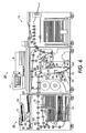
- FIG. 6 shows a schematic front elevation view of an exemplary embodiment of a photoreceptor module 38 in the context of a printing device 10.
- the printing device 10 could be, for example, a xerographic copier or printer.
- an image of an original document or set of documents 11 to be reproduced is projected or scanned onto a uniformly charged surface 13 of a photoreceptor belt 18 to form an electrostatic latent image thereon.
- the latent image is developed with an oppositely charged developing material called toner (not shown) to form a toner image, corresponding to the latent image on the photoreceptor surface.
- the toner image is then electrostatically transferred to a final support material or paper sheet 15, to which it may be permanently fixed by a fusing device 16.
- a set of original documents 11 to be copied is placed on tray 19 of an automatic document handler 20.
- the machine operator enters the desired copying instructions, such as, for example, number of copies or sets of copies, through the control panel 17.
- the automatic document handler transports the documents 11 serially from the tray and past a scanning station 22 which scans each document, thereby producing digital image signals corresponding to the informational areas on the original document.
- the printing device 10 deposits the documents in an output tray 23.
- information and instructions could come from a data storage medium or, if the device is connected to a network, they could come from a remote location such as a desktop computer.
- the image signals are projected upon the uniformly charged surface of the photoreceptor at an imaging station 24 by a raster output system 25 to form a latent electrostatic image of the scanned informational areas of the original document thereon as the photoreceptor is moved passed the imaging station.
- the photoreceptor 18 is in the form of a flexible, endless belt 18 having a photoconductive outer surface 13 and is mounted on a photoreceptor module 38.
- a set of rollers 26A, 26B, 26C and a plurality of backing members located opposite various stations support the belt 18. At least one of the rollers 26A is driven to move the photoreceptor belt 18 in the direction indicated by arrow 21 at a constant rate of speed about the rollers and past the various xerographic processing stations.
- a charging station 28 Before entering the imaging station 24, a charging station 28 uniformly charges the photoreceptor surface 13. Exposing the charged surface of the photoreceptor to the digital signals at the imaging station discharges the photoreceptor surface in the areas struck by the digital image signals. Thus, there remains on the photoreceptor surface a latent electrostatic image in image configuration corresponding to the informational areas on the original. As the photoreceptor continues its movement, the latent electrostatic image thereon passes through developing station 30 which deposits oppositely charged toner on the latent electrostatic image to form a toner image.
- the photoreceptor movement continues transporting the toner image from the developer station to a transfer station 32.
- a paper supply 33 feeds a sheet 15 to a sheet transport 34 for travel to the transfer station.
- the sheet moves into aligned and registered contact with the toner image at a speed synchronistic with the moving photoreceptor.
- the toner image is transferred to the sheet is and the sheet with the toner image is stripped from the photoreceptor belt 18.
- the sheet is then conveyed to a fusing station 36 having fuser device 16, which fuses the toner image to fix permanently the toner image to the sheet.
- the sheet is transported by sheet transporting mechanism 37 to a finishing station 12 where the sheets with the permanent images thereon may be compiled into sets of sheets and finished by being stapled, bound, or the like.
- Suitable drive means (not shown) for the document creating apparatus are arranged to drive the photoreceptor in timed relationship to the scanning of the original document, to forming the latent electrostatic image on the photoreceptor, to effect development of the latent electrostatic image, to separate and feed sheets of paper, to transport same through the transfer station in time registration with the toner image, and to convey the sheet of paper with the toner image through the fusing station to fix the toner image thereto in a timed sequence to produce copies of the original documents.
- the belt In order to drive the endless photoreceptor belt 18 and keep it flat at various stations such as, for example, the development 30 and transfer 32 stations, the belt should be kept at a high level of tension. During idle times, the belt does not need to be kept at as high a tension. Keeping the belt at high tension level during idle times stretches the belt and causes minute cracks to appear. These in turn lead to copy quality defects and shorter belt lifetimes. In order to lengthen the lifetime of photoreceptor belts, it is proposed that photoreceptor belts be detensioned whenever the printer is idle.
- the tension in the belt would be reduced to zero. In the absence of other factors, this would generally lead to the longest lifetime for the belt.
- the photoreceptor belt cannot be fully detensioned. The inside of most modern printing devices are fairly crowded with components. If the belt were fully detensioned, it would tend towards a more circular loop shape and very likely contact surrounding components within the printing device. This could cause damage to both the belt and to the surrounding components. Therefore, the tension is kept at a small but finite amount. In embodiments, the tension on the belt is approximately one-tenth of the normal operating tension.
- the belt should automatically detension by a controlled amount. This could be accomplished by simply programming a controller 8 to detension the belt 18 when the printer entered an idle state.
- the belt usually enters an idle state a predetermined time period after the last print job has completed.
- the machine goes into an idle, lower power consumption mode a predetermined period of time after the last print job had completed. At this point, the tension of the belt is reduced to a lower level.
- the belt tension would be increased up to an operational level.
- the user could manually cause the tension in the belt to reduce to its idle level, when the user was finished.
- the printing device may be equipped with either an automatic retensioning device if a new print job is started, or it may be equipped with a failsafe so it will not restart until the user increases the tension of the belt to an operable level.
- the photoreceptor module 38 can be equipped with a tension control mechanism.
- the tension control mechanism could be external to the photoreceptor module.
- this design would be impractical if not impossible given the space constraints inside typical printing devices.
- the exemplary module 38 in FIG. 1 is equipped with an exemplary detensioning mechanism 50.
- FIG. 1 illustrates the photoreceptor module 38 without its belt 18. With the belt 18 removed, the tensioning member is visible.
- the tensioning member is a tension roller 26C as shown in FIG. 1 .
- the detensioning mechanism 50 is also visible in FIG. 1 .
- the tension roller 26C is used to provide tension in the belt 18.
- Edge guides 78, 80 hold the tension roller 26C in place.
- the tension roller mounting arms (see FIGS. 2-5 ) are connected to the edge guides 78, 80.
- Surrounding the tension roller mounting arms are sleeves 60, 62, which supply a biasing force to the tension roller to keep the tension in the belt sufficiently high for operating purposes.
- the sleeves provide spring-loaded pressure to the tension roller 26C. This pressure keeps the tension roller 26C in an extended state, such that the belt has sufficient tension during operation of the printing device 10.
- the mechanism 50 reduces the amount of tension supplied by the tension roller 26C by reducing the pressure the sleeves apply to the tension roller 26C.
- the mechanism 50 engages and lifts sleeves 60, 62. When the sleeves are lifted, the only force contributing to tension in the belt 18 is gravity acting on the belt 18 and on the roller 26C.
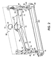
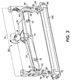
- FIGS. 2-3 offer a better view of the mechanism 50.
- FIG. 2 illustrates the detensioning mechanism 50 when the belt is fully tensioned for printing.
- FIG. 3 shows the mechanism 50 when the belt is detensioned during an idle period.
- the detensioning mechanism 50 includes first and second detensioning arms 52, 54. Each detensioning arm 52, 54 has an inner portion and an outer portion. The outer portion of each arm 52, 54 includes a small arm protrusion 56, 58 at an outer end.
- the mechanism 50 also interacts with the two sleeves 60, 62 that surround the tension roller mounting arms 48, 49. Each sleeve 60, 62 includes a small sleeve protrusion 64, 66.
- the mounting arms 48, 49 are connected to edge guides 78, 80. In FIGS. 2-3 , pins 82, 84, which extend outward from mounting arms 48, 49, and slots 85, 86 in sleeves 60, 62 are visible. These will be described in more detail with respect to FIGS. 4 and 5 .
- the mechanism 50 also includes a cam 68.
- Each detensioning arm 52, 54 is mounted to an arm support frame 70 at a point approximately one third its length from its inner end. Connection holes 72 and 74 are visible in FIGS. 2-3 .
- Cam 68 is also mounted to a cam support frame 76. In FIGS. 1-3 , the detensioning arm support frame 70 and the cam support frame 76 are shown as separate components. However, they may be connected to or integral with each other.
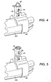
- FIG. 4 illustrates a close up of one end of the tension roller 26C and the corresponding mounting arm 49 sleeve 62, and edge guide 80. In this view, it is easier to see pin 84 and slot 86. Pin 84 extends outward through slot 86 from arm mounting arm 49.
- the sleeve 62 When the photoreceptor belt 18 is at its operating tension, the sleeve 62 is in a lowered position where it pushes downward on pin 84, which, in turn, pushing downward on edge guide 80.
- sleeve 60 pushes downward on pin 82 connected to arm 48, which in turn pushes down on edge guide 78. The combined downward force extends the tension roller to its operating position.
- the cam 68 when the printing device 10 idles for a sufficient amount of time, the cam 68 is rotated (automatically or manually).
- the cam 68 pushes the inner portion of the arm 54 downward.
- the arms are arranged so that the arm 54 applies force to the inner portion of arm 52 as well.
- the arm protrusions 56, 58 contact and press upward on the sleeve protrusions 64, 66.
- the sleeve protrusions 64, 66 raise up and the tension roller no longer has any spring-loaded pressure on it.
- the only force contributing to tension in the belt 18 is gravity acting on both the belt 18 and on the roller 26C.
- the sleeve 62 can be seen in its lifted position. In this position, the sleeve 62 is elevated such that it no longer presses downward on pin 84. Similarly, when the other sleeve 60 is in its raised position, it no longer presses downward on pin 82. In embodiments, the sleeve is raised a distance of approximately 3.5mm.
- sleeve 62 does not lift pin 84. Instead, the tension roller 26C is permitted to essentially hang by its own weight. Reducing tension in the belt 18 to merely that of the weight of the tension roller 26C at its unbiased extension is usually sufficient to reduce wear on the belt. However, if the weight of the tension roller 26C were such that it still caused noticeable wear on the belt, embodiments can also include those where the mechanism 50 raises sleeves 60, 62 such that they apply upward force on pins 82, 84.
- the cam is rotated approximately 180°.
- the amount of rotation necessary to alter the tension from a working higher tension position to an idle lower tension position may be different.
- the basic concept would be the same.
Landscapes
- Physics & Mathematics (AREA)
- General Physics & Mathematics (AREA)
- Discharging, Photosensitive Material Shape In Electrophotography (AREA)
- Electrophotography Configuration And Component (AREA)
- Devices For Conveying Motion By Means Of Endless Flexible Members (AREA)
Claims (6)
- Verfahren zum Verlängern der Lebensdauer eines Fotorezeptorbandes (18), bei dem ein federgespannter Mechanismus einem Spannelement (26c), das das Band auf eine Funktionsspannung spannt, wenn es sich seiner Funktionsposition im Inneren eines Druckgerätes befindet, eine Kraft zuführt, dadurch gekennzeichnet, dass die durch den federgespannten Mechanismus zugeführte Kraft nach unten gerichtet ist, und dadurch, dass das Verfahren des Weiteren Verringern der Spannung an dem Band durch Aufheben der durch den federgespannten Mechanismus (60, 62) zugeführten Kraft an dem Spannelement umfasst, wenn das Druckgerät in einen Ruhezustand übergeht, so dass die einzige Kraft, die zu der Spannung an dem Band beiträgt, auf das Band und auf das Spannelement wirkende Schwerkraft ist, wobei die Ruhespannung wenigstens ein Zehntel der Funktionsspannung beträgt.
- Verfahren nach Anspruch 1, wobei das Band (18) automatisch entspannt wird.
- Verfahren nach Anspruch 2, das des Weiteren umfasst, dass nach einem festen Zeitraum nach dem Drucken des letzten Auftrags festgestellt wird, dass sich das Druckgerät in einem Ruhezustand befindet.
- Verfahren nach einem der vorangehenden Ansprüche, wobei das Band (18) auf eine reduzierte Spannung entspannt wird, die größer ist als 0, jedoch kleiner als die volle Funktionsspannung.
- Verfahren nach einem der vorangehenden Ansprüche, das des Weiteren umfasst:automatisches Erhöhen der Spannung an dem Band (18) von der Ruhespannung auf die Funktionsspannung, wenn das Band (18) eingesetzt wird.
- Verfahren nach einem der vorangehenden Ansprüche, das des Weiteren umfasst:automatisches Verringern der Spannung an dem Band (18) von der Funktionsspannung ausgehend nach einem festen Zeitraum nach Beendigung des letzten Druckauftrags; undautomatisches erneutes Erhöhen der Spannung an dem Band auf die Funktionsspannung, wenn ein neuer Druckauftrag gestartet wird.
Applications Claiming Priority (2)
| Application Number | Priority Date | Filing Date | Title |
|---|---|---|---|
| US667268 | 2000-09-22 | ||
| US10/667,268 US7024136B2 (en) | 2003-09-19 | 2003-09-19 | Method for extending the lifetime of an endless belt |
Publications (2)
| Publication Number | Publication Date |
|---|---|
| EP1517191A1 EP1517191A1 (de) | 2005-03-23 |
| EP1517191B1 true EP1517191B1 (de) | 2013-07-31 |
Family
ID=34194788
Family Applications (1)
| Application Number | Title | Priority Date | Filing Date |
|---|---|---|---|
| EP04255202.6A Expired - Lifetime EP1517191B1 (de) | 2003-09-19 | 2004-08-27 | Verlängerung der Lebensdauer eines endlosen Bandes |
Country Status (5)
| Country | Link |
|---|---|
| US (1) | US7024136B2 (de) |
| EP (1) | EP1517191B1 (de) |
| JP (1) | JP4547215B2 (de) |
| CN (1) | CN100451849C (de) |
| BR (1) | BRPI0404142A (de) |
Families Citing this family (6)
| Publication number | Priority date | Publication date | Assignee | Title |
|---|---|---|---|---|
| KR100495009B1 (ko) * | 2003-07-02 | 2005-06-14 | 삼성전자주식회사 | 화상형성 장치의 전사벨트 텐션 자동 인가 장치 |
| US7155144B2 (en) * | 2004-07-30 | 2006-12-26 | Xerox Corporation | Photoreceptor belt tensioner providing low variation in belt tension as a function of belt length |
| US7526229B1 (en) | 2007-12-27 | 2009-04-28 | Aetas Technology Incorporated | Belt tension mechanism of an image forming device |
| TWI384335B (zh) * | 2008-01-02 | 2013-02-01 | Aetas Technology Inc | 成像裝置之皮帶張力提供機構 |
| US8768216B2 (en) | 2012-08-20 | 2014-07-01 | Xerox Corporation | Control of photoreceptor belt detensioning cycles using extended slower belt rotation |
| US11535455B1 (en) * | 2021-08-06 | 2022-12-27 | Dorner Mfg. Corp. | Tensioning device for an endless belt conveyor |
Family Cites Families (10)
| Publication number | Priority date | Publication date | Assignee | Title |
|---|---|---|---|---|
| US4416532A (en) * | 1982-06-11 | 1983-11-22 | International Business Machines Corporation | Latching and tensioning mechanism for closed-loop belt supporting capstan |
| JPH0451279A (ja) * | 1990-06-20 | 1992-02-19 | Ricoh Co Ltd | ベルト走行装置 |
| US5243384A (en) * | 1991-03-28 | 1993-09-07 | Xerox Corporation | Customer replaceable belt module |
| US5282010A (en) * | 1993-03-23 | 1994-01-25 | Xerox Corporation | Stripping of paper from photoreceptor belts with reduced stress |
| KR100584533B1 (ko) * | 1998-07-21 | 2006-05-30 | 삼성전자주식회사 | 인쇄기용 감광벨트 조정장치 |
| KR100544168B1 (ko) * | 1998-12-07 | 2006-07-25 | 삼성전자주식회사 | 인쇄기의 감광벨트 장력 조절방법 |
| KR100313871B1 (ko) * | 1998-12-07 | 2002-04-17 | 윤종용 | 인쇄기의 감광 벨트 장력 조절장치_ |
| US6101353A (en) * | 1998-12-21 | 2000-08-08 | Xerox Corporation | Flexible photoreceptor belt detensioning for charge transport layer cracking life extension |
| US6269231B1 (en) * | 2000-04-28 | 2001-07-31 | Xerox Corporation | Belt tension variation minimizing mechanism and a reproduction machine having same |
| US6560428B2 (en) * | 2001-10-10 | 2003-05-06 | Xerox Corporation | Tensioning and detensioning assembly |
-
2003
- 2003-09-19 US US10/667,268 patent/US7024136B2/en not_active Expired - Fee Related
-
2004
- 2004-08-27 EP EP04255202.6A patent/EP1517191B1/de not_active Expired - Lifetime
- 2004-09-15 JP JP2004267731A patent/JP4547215B2/ja not_active Expired - Fee Related
- 2004-09-20 BR BR0404142-9A patent/BRPI0404142A/pt not_active IP Right Cessation
- 2004-09-20 CN CNB2004100798126A patent/CN100451849C/zh not_active Expired - Fee Related
Also Published As
| Publication number | Publication date |
|---|---|
| US20050063731A1 (en) | 2005-03-24 |
| JP2005092208A (ja) | 2005-04-07 |
| JP4547215B2 (ja) | 2010-09-22 |
| CN1598712A (zh) | 2005-03-23 |
| US7024136B2 (en) | 2006-04-04 |
| CN100451849C (zh) | 2009-01-14 |
| BRPI0404142A (pt) | 2005-05-24 |
| EP1517191A1 (de) | 2005-03-23 |
Similar Documents
| Publication | Publication Date | Title |
|---|---|---|
| US8447211B2 (en) | Image forming apparatus, image fixing device and image forming system equipped therewith | |
| US7024136B2 (en) | Method for extending the lifetime of an endless belt | |
| US6560428B2 (en) | Tensioning and detensioning assembly | |
| US6024497A (en) | Bushing with molded spring | |
| US20080226321A1 (en) | Image forming apparatus and tandem image forming apparatus | |
| US6973278B2 (en) | Photoreceptor module with multi-functional handle | |
| JP2006267500A (ja) | 画像形成装置およびエッジセンサ | |
| JP3911921B2 (ja) | 連続用紙処理装置およびトラクタ | |
| JPH1124449A (ja) | 画像形成装置 | |
| JP4016635B2 (ja) | 画像形成装置 | |
| JPH11338290A (ja) | 電子写真プリンタ | |
| JPH11295998A (ja) | 画像形成装置 | |
| US5239351A (en) | Reproduction apparatus having an adjustable detack roller assembly | |
| JPH11231645A (ja) | 現像装置及び画像形成装置 | |
| EP3299901A1 (de) | Bilderzeugungsvorrichtung | |
| JP2002296972A (ja) | ベルト搬送装置 | |
| JP4407924B2 (ja) | 画像形成装置 | |
| JP2001265152A (ja) | 画像形成装置における定着装置のクリーニング方法及びクリーニング装置 | |
| JP3532363B2 (ja) | 転写装置 | |
| US20050053395A1 (en) | Photoreceptor module with retracting backer bars | |
| JP3412965B2 (ja) | クリーニング装置 | |
| JPH03231763A (ja) | 画像記録装置 | |
| JP3493953B2 (ja) | 画像形成装置 | |
| JP2000289891A (ja) | 画像形成装置 | |
| JPH01254980A (ja) | 現像装置 |
Legal Events
| Date | Code | Title | Description |
|---|---|---|---|
| PUAI | Public reference made under article 153(3) epc to a published international application that has entered the european phase |
Free format text: ORIGINAL CODE: 0009012 |
|
| AK | Designated contracting states |
Kind code of ref document: A1 Designated state(s): AT BE BG CH CY CZ DE DK EE ES FI FR GB GR HU IE IT LI LU MC NL PL PT RO SE SI SK TR |
|
| AX | Request for extension of the european patent |
Extension state: AL HR LT LV MK |
|
| 17P | Request for examination filed |
Effective date: 20050923 |
|
| AKX | Designation fees paid |
Designated state(s): DE FR GB |
|
| GRAP | Despatch of communication of intention to grant a patent |
Free format text: ORIGINAL CODE: EPIDOSNIGR1 |
|
| INTG | Intention to grant announced |
Effective date: 20130404 |
|
| GRAS | Grant fee paid |
Free format text: ORIGINAL CODE: EPIDOSNIGR3 |
|
| GRAA | (expected) grant |
Free format text: ORIGINAL CODE: 0009210 |
|
| AK | Designated contracting states |
Kind code of ref document: B1 Designated state(s): DE FR GB |
|
| REG | Reference to a national code |
Ref country code: GB Ref legal event code: FG4D |
|
| REG | Reference to a national code |
Ref country code: DE Ref legal event code: R096 Ref document number: 602004042894 Country of ref document: DE Effective date: 20130926 |
|
| PLBE | No opposition filed within time limit |
Free format text: ORIGINAL CODE: 0009261 |
|
| STAA | Information on the status of an ep patent application or granted ep patent |
Free format text: STATUS: NO OPPOSITION FILED WITHIN TIME LIMIT |
|
| 26N | No opposition filed |
Effective date: 20140502 |
|
| REG | Reference to a national code |
Ref country code: DE Ref legal event code: R097 Ref document number: 602004042894 Country of ref document: DE Effective date: 20140502 |
|
| REG | Reference to a national code |
Ref country code: FR Ref legal event code: PLFP Year of fee payment: 13 |
|
| PGFP | Annual fee paid to national office [announced via postgrant information from national office to epo] |
Ref country code: DE Payment date: 20160721 Year of fee payment: 13 Ref country code: GB Payment date: 20160726 Year of fee payment: 13 |
|
| PGFP | Annual fee paid to national office [announced via postgrant information from national office to epo] |
Ref country code: FR Payment date: 20160720 Year of fee payment: 13 |
|
| REG | Reference to a national code |
Ref country code: DE Ref legal event code: R119 Ref document number: 602004042894 Country of ref document: DE |
|
| GBPC | Gb: european patent ceased through non-payment of renewal fee |
Effective date: 20170827 |
|
| REG | Reference to a national code |
Ref country code: FR Ref legal event code: ST Effective date: 20180430 |
|
| PG25 | Lapsed in a contracting state [announced via postgrant information from national office to epo] |
Ref country code: DE Free format text: LAPSE BECAUSE OF NON-PAYMENT OF DUE FEES Effective date: 20180301 Ref country code: GB Free format text: LAPSE BECAUSE OF NON-PAYMENT OF DUE FEES Effective date: 20170827 |
|
| PG25 | Lapsed in a contracting state [announced via postgrant information from national office to epo] |
Ref country code: FR Free format text: LAPSE BECAUSE OF NON-PAYMENT OF DUE FEES Effective date: 20170831 |