EP1517153B1 - Appareil électronique qui determine une caractéristique d'une battérie - Google Patents
Appareil électronique qui determine une caractéristique d'une battérie Download PDFInfo
- Publication number
- EP1517153B1 EP1517153B1 EP04021951.1A EP04021951A EP1517153B1 EP 1517153 B1 EP1517153 B1 EP 1517153B1 EP 04021951 A EP04021951 A EP 04021951A EP 1517153 B1 EP1517153 B1 EP 1517153B1
- Authority
- EP
- European Patent Office
- Prior art keywords
- batteries
- battery
- voltage
- mixed
- electronic apparatus
- Prior art date
- Legal status (The legal status is an assumption and is not a legal conclusion. Google has not performed a legal analysis and makes no representation as to the accuracy of the status listed.)
- Expired - Lifetime
Links
Images


Classifications
-
- H—ELECTRICITY
- H02—GENERATION; CONVERSION OR DISTRIBUTION OF ELECTRIC POWER
- H02J—ELECTRIC POWER NETWORKS; CIRCUIT ARRANGEMENTS OR SYSTEMS FOR SUPPLYING OR DISTRIBUTING ELECTRIC POWER; SYSTEMS FOR STORING ELECTRIC ENERGY
- H02J7/00—Circuit arrangements for charging or discharging batteries or for supplying loads from batteries
- H02J7/50—Circuit arrangements for charging or discharging batteries or for supplying loads from batteries acting upon multiple batteries simultaneously or sequentially
-
- H—ELECTRICITY
- H02—GENERATION; CONVERSION OR DISTRIBUTION OF ELECTRIC POWER
- H02J—ELECTRIC POWER NETWORKS; CIRCUIT ARRANGEMENTS OR SYSTEMS FOR SUPPLYING OR DISTRIBUTING ELECTRIC POWER; SYSTEMS FOR STORING ELECTRIC ENERGY
- H02J7/00—Circuit arrangements for charging or discharging batteries or for supplying loads from batteries
- H02J7/80—Circuit arrangements for charging or discharging batteries or for supplying loads from batteries including monitoring or indicating arrangements
- H02J7/82—Control of state of charge [SOC]
Definitions
- the invention relates to an electronic apparatus which is powered by a plurality of batteries connected in series and more particularly to an electronic apparatus which prevents different types of batteries from being mixed by determining the characteristic of each battery to ensure safe usage thereof.
- JP HEI11-260425 A discloses an apparatus for detecting an inverse battery connection to insure a positive electrode and a negative electrode of each battery is mounted in a proper direction.
- a plurality of batteries accommodated in an accommodating container are divided into a plurality of blocks for connection in series.
- a synthetic voltage of each block is detected to compare voltages in order to detect whether any battery is connected inversely. If an inversely connected battery is found, the supply of electric power is stopped to avoid overheating caused by the inverse connection of the battery, leakage of chemical fluid, or other related problems.
- the conventional inverse battery connection detecting apparatus discussed above is capable of detecting an inversely connected battery in and among a plurality of batteries connected in series
- the conventional inverse battery connection detecting apparatus is incapable of detecting a battery having a different characteristic, namely, a battery whose nominal voltage, type, or the like, is different (for example, manganese battery and alkaline battery) from the remaining plurality of batteries, or a battery whose remaining capacity is different (for example, unused battery and consumed battery) from the remaining plurality of batteries connected in series.
- the conventional apparatus is incapable of detecting its existence and the battery continues to be used. As a result, the apparatus may function improperly. Additionally, battery life may be shortened because when the discharge characteristics of respective batteries are different, an excessive usage condition may occur, thereby leading to leakage of fluid from the battery due to excessive discharge, or the like. Further, deterioration of the battery is accelerated.
- the invention resolves the above-described problems and provides an electronic apparatus which is powered by a plurality of batteries connected in series. If a battery having a different characteristic is present, the apparatus detects its existence and stops the apparatus from operating, to prevent a leakage of fluid from the battery, abnormal operation of the apparatus and the like, thereby ensuring safe usage of the apparatus.
- an electronic apparatus according to claim 1.
- a method for controlling an electronic apparatus according to claim 8 is provided.
- this aspect of the invention enables the detection of its existence by comparing the first voltage with the second voltage.
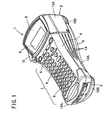
- Fig. 1 is a schematic appearance perspective view of a tape printing apparatus of an embodiment
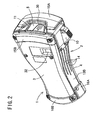
- Fig. 2 is a schematic appearance perspective view of the tape printing apparatus of the embodiment as seen from its rear side;
- Fig. 3 is a perspective view of the interior of the lower unit in the tape printing apparatus of the embodiment
- Fig. 4 is a diagram showing a battery characteristic detecting mechanism of the embodiment
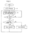
- Fig. 5 is a flow chart of a main system control program of the tape printing apparatus of the embodiment.
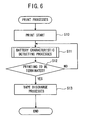
- Fig. 6 is a flow chart of a print control program for the tape printing apparatus of the embodiment.
- Fig. 7 is an explanatory diagram showing schematically the battery by electromotive force and internal resistance
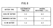
- Fig. 8 is a diagram showing an example of electromotive force and internal resistance of each of various kinds of batteries
- Fig. 9A is an explanatory diagram showing the terminal voltage of an alkaline battery when current load is small
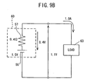
- Fig. 9B is an explanatory diagram showing the terminal voltage of an alkaline battery when current load is large
- Fig. 10A is an explanatory diagram showing the terminal voltage of a manganese battery when current load is small
- Fig. 10B is an explanatory diagram showing the terminal voltage of a manganese battery when current load is large;
- Fig. 11A is an explanatory diagram showing the terminal voltage of a Ni-MH battery when current load is small
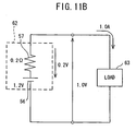
- Fig. 11B is an explanatory diagram showing the terminal voltage of a Ni-MH battery when current load is large;
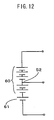
- Fig. 12 is a circuit diagram of an arrangement of batteries when an alkaline battery and a manganese battery are mixed;
- Fig. 13 is a circuit diagram showing a case where an alkaline battery and a manganese battery are mixed;
- Fig. 14 is a diagram showing each voltage value when an alkaline battery and a manganese battery are mixed
- Fig. 15 is a circuit diagram of an arrangement of batteries when an alkaline battery and a manganese battery are mixed;
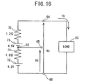
- Fig. 16 is a circuit diagram showing a case where an alkaline battery and a Ni-MH battery are mixed;
- Fig. 17 is a diagram showing each voltage value when an alkaline battery and a Ni-MH battery are mixed.
- Fig. 18 is a flow chart of battery characteristic detection processing program in the tape printing apparatus of the embodiment.
- a tape printing apparatus which includes an exemplary embodiment of the electronic apparatus of the invention, is described in detail with reference to the accompanying drawings.
- Fig. 1 is a perspective view showing an entire tape printing apparatus.
- Fig. 2 is a perspective view showing the rear side of the tape printing apparatus.
- the tape printing apparatus 1 comprises a main body 2 made of polystyrene, or any suitable material, and a rear cover 3 made of polystyrene, or any suitable material, mounted detachably so as to cover the entire rear face (a face opposite to a face opposing user when the tape printing apparatus 1 is used) of this main body 2.
- the main body 2 comprises an upper unit 4 and a lower unit 5.
- the upper unit 4 has a key arrangement section 7 in which various kinds of keys 6, such as character keys for inputting characters, print key for executing print and the like, are disposed on the surface thereof.
- a lateral window section 8 is disposed in the right/left direction substantially in the center of the surface on its top face.
- a display 9 for displaying characters and the like inputted through the key 6 is disposed in this window section 8.
- a cutter lever 10 is provided on the left side face of the display 9 of the main body 2. By pressing this cutter lever 10 inward, a tape 12 (see Fig. 3 ) discharged from a tape discharge slot 11 formed at a top end section can be cut out with a cutter (not shown).
- the tape 12 is comprised of an image receiving paper on which characters are printed, an adhesive layer and a separator for preventing the adhesive surface from sticking to an undesired portion.
- the lateral width of the upper unit 4 having the key arrangement section 7 is smaller than the lateral width of a section having the window section 8.
- Grip members 13A, 13B are attached to both sides of the lower unit 5.
- the grip members 13A, 13B are formed of a styrene based elastomer resin, or any suitable elastic material, to prevent slippage and constructed to be gripped easily by an operator. Because the grip members 13A, 13B are mounted to form the same plane as the main body 2 and the rear cover 3 as described later, there is no fear that a user's finger may be caught by an end section of the grip members 13A, 13B. Further, three protruding rows 14 are formed in parallel to the apparatus on the surface of the grip members 13A, 13B to better prevent slippage.
- the tape printing apparatus 1 has a first protector member 15A, 15B for covering an end section provided with a display 9 and a second protector member 16A, 16B which is formed separately from the first protector member 15A, 15B for covering an end section on an opposite side to the end section provided with the display 9.
- the respective protector members 15A, 15B, 16A, 16B are constructed of the upper unit 4, the lower unit 5 and the rear cover 3 separately.
- a first protector member 15A and a second protector member 16A are attached to the upper unit 4 and the lower unit 5, and a first protector member 15B and a second protector member 16B are attached to the rear cover 3.
- the protector members 15A , 15B , 16A, 16B are formed of styrene base resin or any suitable material having elasticity like the aforementioned grip member 13, the protector members 15A, 15B, 16A, 16B relax an impact which occurs when the tape printing apparatus 1 drops, thereby protecting the exterior face of the apparatus from damage.
- Fig. 3 is a perspective view showing the tape printing apparatus when the rear cover is detached as viewed from the rear side.
- the lower unit 5 is provided with a cassette accommodating section 21, which is substantially of the same shape as the external shape of a tape cassette 20, and protrudes by an amount equal to the thickness of the tape cassette 20 from the rear face.
- a thin thermal head mounting section 23 is erected, on which a thermal head 22 is to be mounted, at a right angle along the length direction of the apparatus.
- a platen holder (not shown) is provided rotatably at a drive section 24 provided on the side portion of the cassette accommodating section 21 opposite the thermal head 22.
- the six batteries accommodated in the battery accommodating section 27 are connected in series.
- a control circuit (not shown) in which a control circuit section is constructed is disposed inside the upper unit 4.
- a second insertion section 30 provided on an opposite side to the first insertion section 28 at the rear cover 3 is engaged with a fixing section (not shown) provided on the lower unit 5. Consequently, the rear cover 3 is attached to the bottom of the tape printing apparatus. Because it is so constructed, the second insertion section 30 may be released from the fixing section when the second insertion section 30 is pushed inward of the apparatus, with the rear cover 3 mounted thereto. Thus, the rear cover 3 is easily detachable from the lower unit 5.
- the tape cassette 20 can be taken out from the cassette accommodating section 21. Batteries accommodated in the battery accommodating section 27 can also be taken out successively and replaced. Because the protector members 15A, 15B, 16A, 16B are constructed separately between the main body 2 and the rear cover 3, the rear cover can be opened/closed without detaching the respective protector members 15A, 15B, 16A, 16B from the tape printing apparatus 1.
- the rear cover 3 has a check window 32 at a section opposing the tape cassette 20 accommodated in the lower unit 5 and the protector member 15B is attached to the rear cover 3 without covering this check window 32. Therefore, the type of the tape cassette 20 accommodated in the cassette accommodating section 21 can be confirmed through this check window 32 without opening the rear cover 3.
- the first protector member 15A As shown in Fig. 2 , the first protector member 15A, at a section covering a top face on the side of the display 9 of the tape printing apparatus 1, is cut out so as not to cover the tape discharge slot 11 and the second insertion section 30. Consequently, the first protector member 15A does not obstruct discharge of the tape 12 when the first protector member 15A is mounted on the side of the display 9. Further, when the rear cover 3 is detached from the lower unit 5, the operation of pressing the second insertion section 30 into the inside of the apparatus is not obstructed. Therefore, a printed tape 12 can be discharged from the tape discharge slot 11 with the first protector member 15A mounted and the rear cover 3 can be detached from the lower unit 5 by pressing the second insertion section 30 into the inside of the apparatus.
- the surface of the second insertion section 30 is lower than the surface of the first protector member 15A, i.e., concaved.
- the tape printing apparatus 1 drops on the ground, there is no fear that the second insertion section 30 may be pressed in so that the rear cover 3 becomes detached because the first protector member 15A would make contact with the ground before the second insertion section 30.
- Fig. 4 is an entire diagram showing the entire structure of the battery characteristic detecting mechanism of the tape printing apparatus of this embodiment.
- the battery characteristic detecting mechanism 36 of this exemplary embodiment comprises a control circuit section 37, six batteries 38 connected in series, a first switch 40 for controlling the supply of power to a load 39, resistors 41, 42, 43, 44, a second switch 45 for controlling the supply of power to each resistor and the control substrate section 37, a third switch 46, and a voltage regulator circuit 47 for adjusting a voltage applied to the control circuit section 37.
- the control circuit section 37 that includes a battery characteristic detecting section, comprises a liquid crystal display 9, first analog to digital converter (hereinafter abbreviated as A/D) input 48 and second A/D input 49 for measuring a voltage, a voltage comparator circuit 50 for comparing a voltage and a CPU 51 for controlling the respective devices.
- the second switch 45 and the third switch 46 are turned on, so that electric power is supplied to the control circuit section 37. Further, these switches are turned off to shut down the power to the tape printing apparatus 1.
- the first switch 40 is connected to the CPU 51 and turned on for the above-described print operation and turned off for other processes than printing.
- the load 39 is constituted of the thermal head 22 and a drive motor contained in the tape carrying mechanism.
- the resistors 41, 42 are connected in series and connected to the six batteries through the second switch 45 in parallel. Because the resistor 41 and resistor 42 are set at the ratio of 5:1 in terms of resistance value, a voltage 1/6 the voltage (first voltage) of the six entire batteries 38 is detected between the resistor 41 and the resistor 42.
- the first A/D input 48 is connected between the resistor 41 and the resistor 42 and a voltage which is 1/6 the first voltage is measured. This measured voltage is an average voltage of a single battery of the six batteries.
- An end of the resistor 43 is connected to a connecting point 52, which divides the six batteries to three batteries each, through the third switch 46.
- the other end of the resistor 43 is connected to an end of the resistor 44 and the other end of the resistor 44 is grounded. Because the resistances of the resistor 43 and resistor 44 are set to 2:1, a voltage produced by dividing the voltage (second voltage) of the batteries 38 of three batteries separated by the connecting point 52 from the other three is detected between the resistor 43 and resistor 44.
- the second A/D input 49 is connected between the resistor 43 and resistor 44 to measure a voltage produced by dividing the second voltage by three. This measured voltage is an average voltage for each battery to the three batteries on the grounding side separated by the connecting point 52. Therefore, the battery characteristic detecting mechanism 36 is capable of measuring an average voltage of each battery with the respective resistors 41, 42, 43, 44 for the first voltage and second voltage.
- the voltage regulator circuit 47 adjusts a voltage applied to the battery characteristic detecting section 36 to a constant level. According to this exemplary embodiment, the voltage is adjusted to 5V.
- the connecting point 52 is set up between the third and fourth batteries to detect the voltage of the three batteries 38 as the second voltage
- the connecting point which detects the voltage of 1-5 batteries as the second voltage by changing the ratio in resistance of the resistors 43, 44 may be set arbitrarily in an interval from between the first and second batteries 38 to between the fifth and sixth batteries 38. Needless to say, the ratio between the resistor 43 and resistor 44 is changed so as to detect an average voltage of each battery to the second voltage between the resistor 43 and resistor 44 corresponding to the set connecting point 52.
- the average voltage of the first voltage and second voltage measured by the first A/D input 48 and second A/D input 49 is compared by the voltage voltage comparator circuit 50
- the CPU 51 judges the battery characteristic based on a comparison result and controls the supply of power with the first switch 40, second switch 45 and third switch 46 as required.
- Fig. 5 is a flow chart for the main system control program of the tape printing apparatus 1.
- step S1 initialization, such as clearing of each memory, is carried out.
- battery characteristic detecting processes for detecting whether any battery having a different characteristic is mixed is carried out by the battery characteristic detecting mechanism 36. The detail of the battery characteristic detecting processes will be described later.
- S4 whether an inputted key is print key is determined and if the inputted key is the print key (S4: YES), the procedure returns to S2 after print processes are executed based on the inputted data (S5). If no printing processes are executed (S4: NO), the procedure returns to S2 after other processes corresponding to the particular inputted key, for example, input, deletion, edition, or the like, of character data is executed.
- Fig. 6 is a flow chart of the print control program.
- the battery characteristic detecting processes (S11) during print is executed for every print of a line according to this embodiment, it may be executed for any line number other than every line.
- tape discharge processes are carried out.
- a tape 12 printed through the thermal head 22 is carried and discharged from the tape discharge slot 11. Then, by pressing the cutter lever 10 inward, the tape 12 discharged from the tape discharge slot 11 can be cut by a cutting blade (not shown).
- the battery power can be expressed with an equivalent voltage source in which an electromotive force E and an internal resistance r are connected in series.
- Fig. 7 is an explanatory diagram which expresses the battery schematically with the electromotive force and internal resistance.
- a battery 55 can be expressed in the form that the electromotive force 56 and internal resistance 57 are connected in series.
- the electromotive force 56 and internal resistance 57 each have a specified value depending on the type of battery 55.
- Fig. 8 shows an example of the electromotive force 56 and internal resistance 57 for several types of batteries.
- the electromotive force 56 of an alkaline battery is 1.5 V and the internal resistance 57 is 0.4 ⁇ .
- the electromotive force 56 of a manganese battery (primary battery) is 1.5 V and the internal resistance 57 is 1.2 ⁇ .
- the electromotive force 56 of a Ni-MH battery (secondary battery / storage battery) is 1.2 V and the internal resistance 57 is 0.2 ⁇ .
- a difference in terminal voltage is generated depending on the quantity of current flowing through a circuit, that is, the magnitude of a current load applied to a battery in various types of batteries each having a different value in the electromotive force 56 and internal resistance 57.
- Fig. 9A is an explanatory diagram showing the terminal voltage of the alkaline battery 60 when the current load is small (draws low current).
- Fig. 9B is an explanatory diagram showing the terminal voltage of the alkaline battery 60 when the current load is large.
- Fig. 10A is an explanatory diagram showing the terminal voltage of the manganese battery 61 when the current load is small.
- Fig. 10B is an explanatory diagram showing the terminal voltage of the manganese battery 61 when the current load is large (draws high current).
- Fig. 11A is an explanatory diagram showing the terminal voltage of a Ni-MH battery 62 when the current load is small.
- Fig. 11B is an explanatory diagram showing the terminal voltage of the Ni-MH battery 62 when the current load is large.
- the terminal voltage of each battery is 1.46 V for the alkaline battery 60, 1.38 V for the manganese battery 61 and 1.18 V for the Ni-MH battery 62.
- the voltage between the alkaline battery 60 and the manganese battery 61 is difficult to compare because a difference in voltage therebetween is minute, it is easy to distinguish between the alkaline battery 60 and manganese battery 61 and between the manganese battery 61, and the Ni-MH battery 62, because the difference in voltage is as large as 0.28 and 0.20V, respectively.
- the terminal voltage of each kind of the battery is 1.1 V for the alkaline battery 60, 0.3 V for the manganese battery 61 and 1.0 V for the Ni-MH battery 62.
- an average voltage per battery of the entire batteries is compared with an average voltage per battery at an arbitrary connecting point by the battery characteristic detecting mechanism 36, as described above.
- Fig. 12 is a circuit diagram of battery connection when the alkaline batteries and manganese batteries are mixed.
- Fig. 13 is a circuit diagram showing a case where the alkaline batteries and manganese batteries are mixed.
- Fig. 14 is a diagram showing respective voltage values when the alkaline batteries and manganese batteries are mixed.
- the total electromotive force of the three batteries (between points (nodes) 64 and 65) constituted of only the alkaline batteries 60 is 4.5 V and the total internal resistance is 1.2 ⁇ .
- the total electromotive force of three batteries (between points (nodes) 65 and 66) including the manganese battery 61 is 4.5 V and the total internal resistance is 2.0 ⁇ .
- the voltage Va of the entire six batteries, including the alkaline batteries 60 and manganese batteries 61 (voltage between points 64 and 66), is 8.68 V if a current Ia flowing through a circuit is small (0.1 A).
- the voltage of the three batteries (voltage between points 65 and 66) on the low voltage side, including the manganese batteries 61, separated by the connecting point 52 is 4.3 V. If the current Ia flowing through a circuit is large (1.0 A), the Va is 5.8 V and the Vb is 2.5 V.
- V1 is 1.45 V when the current Ia flowing through a circuit is small (0.1 A) and V2 is 1.43 V.
- V1 is 0.97 V and V2 is 0.83 V.
- Fig. 15 is a circuit diagram of battery connection indicating a case where the alkaline batteries and Ni-MH batteries are mixed.
- Fig. 16 is a circuit diagram showing a case where the alkaline batteries and Ni-MH batteries are mixed.
- Fig. 17 is a diagram showing respective voltage values when the alkaline batteries and Ni-MH batteries are mixed.
- the total electromotive force of the three batteries (between points 64 and 65) constituted of only the alkaline batteries 60 is 4.5 V and the total internal resistance is 1.2 ⁇ .
- the total electromotive force of the three batteries (between points 65 and 66), including the Ni-MH batteries 62, is 4.2 V and the total internal resistance is 1.0 ⁇ .
- the voltage (voltage between points 64 and 66) Vc of all six batteries, including the alkaline batteries 60 and Ni-MH batteries 62, is 8.48 V when a current Ib flowing through the circuit is small (0.1A).
- the voltage (voltage between points 65 and 66) Vd of the three batteries on the low voltage side separated by the connecting point 52 is 4.1 V. If the current Ib flowing through the circuit is large (1.0 A), the Vc is 6.5 V and the Vd is 3.2 V.
- V1 is 1.41 V when the current Ib flowing through a circuit is small (0.1 A) and V2 is 1.37 V. Further, when the current Ib flowing through the circuit is large (1.0 V), V1 is 1.08 V and V2 is 1.07 V.
- the first A/D input 48 and the second A/D input 49 which are used in this embodiment, can detect about a 0.01V or larger difference of the input voltage. In other words, resolution of the first A/D input 48 and the second A/D input 49, which are used in this embodiment, is about 0.01V.
- a tolerable voltage difference ⁇ V is set to 0.03 V and when the voltage difference
- the current value is low, that is, when a current load applied to the battery is small, it comes that the voltage difference between the averages V1 and V2,
- the detection of the mixing is enabled.
- the battery characteristic detecting processes (S11) during print processes by comparing the battery voltages, mixing of a battery having a different voltage characteristic when the current value is high can be detected, namely, mixing of a battery having a different voltage when the current load applied to the battery is large can be detected. For example, mixing of the alkaline batteries 60 and manganese batteries 61 can be detected.
- a battery having a different usage time is mixed (for example, if a consumed battery is mixed in unused batteries), a battery having a long usage time lowers its terminal voltage, as compared to a battery having a short usage time when the current load is large. Thus, by comparing the voltages, mixing of a battery having a different usage time can be detected.
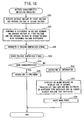
- Fig. 18 is a flow chart of a battery characteristic detecting processing program.
- the first A/D input 48 detects the average voltage V1 per battery obtained by dividing the first voltage of the all batteries 38 connected in series with the resistors 41, 42.
- the second A/D input 49 detects the average voltage V2 per battery obtained by dividing the second voltage of batteries on the grounding side with respect to any connecting point, and the batteries connected in series, with the resistors 43, 44. The procedure then proceeds to S21.
- the voltage voltage comparator circuit 50 compares the voltage difference
- the tolerable voltage difference ⁇ V is 0.03 V and this value is stored in a nonvolatile memory connected to the CPU 51.
- a voltage comparison signal is read by the CPU 51 (S23) and the battery characteristic is determined based on the voltage comparison signal (S24). If the voltage comparison signal outputted from the voltage voltage comparator circuit 50 is "0", it is determined that any battery having a different characteristic is not mixed (S24: YES) and the operation is continued (S25). On the other hand, if the voltage comparison signal outputted from the voltage voltage comparator circuit 50 is "1", it is determined that a battery having a different characteristic is mixed (S24: NO), the supply of power to the load 39 is stopped by turning off the first switch 40 and the current operation is interrupted (S26). After that, an alarm message is displayed on the display 9 for about 10 seconds (S27).
- the alarm messages to be displayed on the display 9 include, for example, "battery check”, “battery error”, “battery mixing”, “change batteries”, and the like.
- a more detailed description of the alarm message may be included in the operation manual of the tape producing apparatus 1 or contained in a label or the like and this may be attached to the tape producing apparatus 1.
- the battery characteristic detecting processes are executed prior to key input and during printing, it may be carried out after the print is finished or during activation of a drive motor.
- the average voltage V1 per battery of the first voltage of the plural batteries 38 connected in series and the average voltage V2 per battery of the second voltage of the batteries 38 at the connecting point 52 are detected (S20), the voltage difference
- an abnormal operation of the tape producing apparatus 1 which may be caused by continuing the usage in a condition that a battery having a different characteristic is mixed in the batteries 38 accommodated in the battery accommodating section 27 and fluid leakage of the batteries 38 are prevented to ensure the safety use. Additionally because the alarm message is displayed on the display before the power is turned off, the operator can be notified that a battery having a different characteristic is mixed in the batteries 38 accommodated in the battery accommodating section 27 and the power is shut down for the safety before the supply of power is shut down.
Landscapes
- Engineering & Computer Science (AREA)
- Power Engineering (AREA)
- Charge And Discharge Circuits For Batteries Or The Like (AREA)
- Secondary Cells (AREA)
- Tests Of Electric Status Of Batteries (AREA)
- Power Sources (AREA)
- Primary Cells (AREA)
- Printers Characterized By Their Purpose (AREA)
Claims (11)
- Appareil électronique qui reçoit une énergie électrique d'une pluralité de batteries (38) connectées en série, comprenant :des moyens de détection (36) détectant une première tension (Va, Vc) de la somme de la pluralité de batteries (38) connectées en série et une deuxième tension (Vb, Vd) de batteries connectées en série en un point de connexion (52) quelconque entre la pluralité de batteries (38) ;
etdes moyens de détermination (51) déterminant une caractéristique de batterie sur la base de la première tension (Va, Vc) et de la deuxième tension (Vb, Vd) ;caractérisé en ce queles moyens de détermination (51) comprennent :des premiers moyens de détermination déterminant si les batteries principales et les batteries secondaires sont mélangées dans la pluralité de batteries (38) lorsque la charge de courant (39, 63) appliquée à la pluralité de batteries (38) est faible ; etdes deuxièmes moyens de détermination déterminant si une pluralité de types de batteries sont mélangés dans la pluralité de batteries (38) lorsque la charge de courant (39, 63) appliquée à la pluralité de batteries (38) est grande. - Appareil électronique selon la revendication 1, comprenant en outre :des moyens d'acquisition de tension moyenne acquérant une première tension moyenne (V1) pour la pluralité de batteries (38) à partir de la première tension (Va, Vc) détectée par les moyens de détection (36) et une deuxième tension moyenne (V2) pour une pluralité de batteries à partir de la deuxième tension (Vb, Vd) détectée par les moyens de détection (36) ; etdes moyens de comparaison (50) comparant la première tension moyenne (V1) avec la deuxième tension moyenne (V2), dans lequel les moyens de détermination (51) déterminent la caractéristique de batterie sur la base d'un résultat de comparaison des moyens de comparaison (50).
- Appareil électronique selon la revendication 1 ou 2, dans lequel les moyens de détermination (51) déterminent la caractéristique de batterie lorsque la charge de courant (39, 63) appliquée à la pluralité de batteries (38) est faible.
- Appareil électronique selon la revendication 1 ou 2, dans lequel les moyens de détermination (51) déterminent la caractéristique de batterie lorsque la charge de courant (39, 63) appliquée à la pluralité de batteries (38) est grande.
- Appareil électronique selon la revendication 1 ou 2, dans lequel les premiers moyens de détermination déterminent une première caractéristique de batterie lorsque la charge de courant (39, 63) appliquée à la pluralité de batteries (38) est faible et les deuxièmes moyens de détermination déterminent une deuxième caractéristique de batterie lorsque la charge de courant (39, 63) appliquée à la pluralité de batteries (38) est grande.
- Appareil électronique selon la revendication 1 ou 2, dans lequel, lorsque les premiers moyens de détermination déterminent que les batteries principales et les batteries secondaires sont mélangées dans la pluralité de batteries (38) ou lorsque les deuxièmes moyens de détermination déterminent que la pluralité de types de batteries sont mélangés dans la pluralité de batteries (38), l'alimentation à partir de la pluralité de batteries (38) est coupée.
- Appareil électronique selon la revendication 1, 2 ou 6, comprenant en outre un afficheur (9), dans lequel, lorsque les premiers moyens de détermination déterminent que les batteries principales et les batteries secondaires sont mélangées dans la pluralité de batteries (38) ou lorsque les deuxièmes moyens de détermination déterminent que la pluralité de types de batteries sont mélangés dans la pluralité de batteries (38), une alarme est fournie sur l'afficheur (9).
- Procédé pour commander un appareil électronique qui reçoit une énergie électrique d'une pluralité de batteries (38) connectées en série, comprenant :la détection d'une première tension (Va, Vc) de la somme de la pluralité de batteries (38) connectées en série ; etla détection d'une deuxième tension (Vb, Vd) d'une pluralité de batteries connectées en série en un point de connexion quelconque entre la pluralité de batteries (38) ; etla détermination d'une caractéristique de batterie sur la base de la première tension (Va, Vc) et de la deuxième tension (Vb, Vd),caractérisé par :la détermination si les batteries principales et les batteries secondaires sont mélangées dans la pluralité de batteries (38) lorsque la charge de courant (39, 63) appliquée à la pluralité de batteries (38) est faible ; etla détermination si une pluralité de types de batteries sont mélangés dans la pluralité de batteries (38) lorsque la charge de courant (39, 63) appliquée à la pluralité de batteries (38) est grande.
- Procédé pour commander un appareil électronique selon la revendication 8, comprenant en outre :la détermination d'une première caractéristique de batterie lorsque la charge de courant (39, 63) appliquée à la pluralité de batteries (38) est faible ; et/oula détermination d'une deuxième caractéristique de batterie lorsque la charge de courant (39, 63) appliquée à la pluralité de batteries (38) est grande.
- Procédé pour commander un appareil électronique selon la revendication 8 ou 9, comprenant en outre l'arrêt de l'alimentation à partir de la pluralité de batteries (38) lorsqu'il est déterminé que les batteries principales et les batteries secondaires sont mélangées dans la pluralité de batteries (38) ou lorsqu'une pluralité de types de batteries sont mélangés dans la pluralité de batteries (38).
- Procédé pour commander un appareil électronique selon la revendication 8, 9 ou 10, comprenant en outre la fourniture d'une alarme sur un afficheur (9) lorsqu'il est déterminé que les batteries principales et les batteries secondaires sont mélangées dans la pluralité de batteries (38) ou lorsque la pluralité de types de batteries sont mélangés dans la pluralité de batteries (38).
Applications Claiming Priority (4)
| Application Number | Priority Date | Filing Date | Title |
|---|---|---|---|
| JP2003322893 | 2003-09-16 | ||
| JP2003322893 | 2003-09-16 | ||
| JP2004057538A JP4111150B2 (ja) | 2003-09-16 | 2004-03-02 | 電子機器 |
| JP2004057538 | 2004-03-02 |
Publications (2)
| Publication Number | Publication Date |
|---|---|
| EP1517153A1 EP1517153A1 (fr) | 2005-03-23 |
| EP1517153B1 true EP1517153B1 (fr) | 2013-08-21 |
Family
ID=34197202
Family Applications (1)
| Application Number | Title | Priority Date | Filing Date |
|---|---|---|---|
| EP04021951.1A Expired - Lifetime EP1517153B1 (fr) | 2003-09-16 | 2004-09-15 | Appareil électronique qui determine une caractéristique d'une battérie |
Country Status (4)
| Country | Link |
|---|---|
| US (1) | US7417406B2 (fr) |
| EP (1) | EP1517153B1 (fr) |
| JP (1) | JP4111150B2 (fr) |
| CN (1) | CN1333321C (fr) |
Families Citing this family (14)
| Publication number | Priority date | Publication date | Assignee | Title |
|---|---|---|---|---|
| TWI286212B (en) * | 2004-11-03 | 2007-09-01 | Mediatek Inc | Battery detecting system |
| JP4950459B2 (ja) * | 2005-08-25 | 2012-06-13 | キヤノン株式会社 | 駆動装置及びその制御方法、並びに制御プログラム及び記憶媒体 |
| JP4432985B2 (ja) * | 2007-03-12 | 2010-03-17 | ソニー株式会社 | 電池パック |
| US7545161B2 (en) * | 2007-08-02 | 2009-06-09 | International Business Machines Corporation | Method and apparatus to measure threshold shifting of a MOSFET device and voltage difference between nodes |
| US7696912B2 (en) * | 2008-05-02 | 2010-04-13 | Exar Corporation | Interrupt based multiplexed current limit circuit |
| JP5099449B2 (ja) * | 2008-09-24 | 2012-12-19 | ブラザー工業株式会社 | 電子機器 |
| DE102011076086A1 (de) * | 2011-05-19 | 2012-11-22 | Hilti Aktiengesellschaft | Bolzensetzgerät und Verfahren zum Betreiben eines Bolzensetzgeräts |
| US9524018B2 (en) * | 2013-08-30 | 2016-12-20 | Dell Products, Lp | Adaptive integral battery pack and voltage regulator |
| JP2015118062A (ja) * | 2013-12-20 | 2015-06-25 | オプテックス株式会社 | 電池種類判別装置およびこれを備えた電池駆動型の電子機器 |
| CN104767260B (zh) * | 2015-03-30 | 2017-04-05 | 华为技术有限公司 | 充电器、终端设备和充电系统 |
| JP6358216B2 (ja) * | 2015-09-25 | 2018-07-18 | ブラザー工業株式会社 | 印刷装置 |
| US10343552B2 (en) * | 2017-02-08 | 2019-07-09 | Samsung Electronics Co., Ltd. | Heterogeneous electrical energy storage system |
| CN108983101B (zh) * | 2017-06-02 | 2020-11-10 | 中国移动通信集团河北有限公司 | 蓄电池容量分析方法、装置、设备和计算机可读存储介质 |
| TWI878693B (zh) * | 2022-07-07 | 2025-04-01 | 仁寶電腦工業股份有限公司 | 電池模組及其操作方法 |
Family Cites Families (19)
| Publication number | Priority date | Publication date | Assignee | Title |
|---|---|---|---|---|
| US4316185A (en) * | 1980-07-17 | 1982-02-16 | General Electric Company | Battery monitor circuit |
| JPS63172972U (fr) * | 1987-04-30 | 1988-11-10 | ||
| US4849682A (en) * | 1987-10-30 | 1989-07-18 | Anton/Bauer, Inc. | Battery charging system |
| JP2503526Y2 (ja) * | 1990-08-23 | 1996-07-03 | 株式会社ニコン | 電池の異常検出回路 |
| KR950002762B1 (ko) * | 1992-05-20 | 1995-03-24 | 금성통신주식회사 | 니켈-카드뮴/알카린 밧테리 인식방법 및 인식장치 |
| US6043625A (en) * | 1993-07-29 | 2000-03-28 | Eastman Kodak Company | Battery charging system with battery type and polarity discrimination |
| DE19611544A1 (de) * | 1995-03-24 | 1996-10-02 | Licentia Gmbh | Verfahren und Schaltungsanordnung zum Prüfen einer Einrichtung zum Speichern elektrischer Energie |
| DE29623955U1 (de) | 1995-03-24 | 2001-01-04 | AEG SVS Power Supply Systems GmbH, 59581 Warstein | Schaltungsanordnung zum Prüfen einer Einrichtung zum Speichern elektrischer Energie |
| JPH1038932A (ja) * | 1996-07-18 | 1998-02-13 | Minikamu Res:Kk | 電池パックの電池の性能劣化検出装置、電池充電装置及び直流電源装置 |
| US6020743A (en) * | 1997-10-21 | 2000-02-01 | Compaq Computer Corporation | Method and apparatus for detecting failed batteries |
| JP3936048B2 (ja) * | 1997-12-09 | 2007-06-27 | トヨタ自動車株式会社 | 電池制御装置 |
| JP4003278B2 (ja) * | 1998-02-20 | 2007-11-07 | ソニー株式会社 | 電池の電圧検出回路と電池の電圧検出方法 |
| JPH11250942A (ja) * | 1998-02-27 | 1999-09-17 | Sony Corp | 電池の種類検出方法及び電池の種類検出装置 |
| JPH11260425A (ja) * | 1998-03-11 | 1999-09-24 | Matsushita Graphic Communication Systems Inc | 電池の逆接続検出装置 |
| JPH11266542A (ja) * | 1998-03-16 | 1999-09-28 | Sony Corp | 電源回路 |
| JP3925002B2 (ja) * | 1999-09-21 | 2007-06-06 | 株式会社デンソー | 組電池の電圧調整装置 |
| JP3300309B2 (ja) * | 1999-10-19 | 2002-07-08 | 本田技研工業株式会社 | 電池電圧測定装置 |
| JP2003031269A (ja) * | 2001-07-13 | 2003-01-31 | Kyocera Corp | 電池残量判定装置及びその方法並びに携帯端末 |
| US6963186B2 (en) * | 2003-02-28 | 2005-11-08 | Raymond Hobbs | Battery charger and method of charging a battery |
-
2004
- 2004-03-02 JP JP2004057538A patent/JP4111150B2/ja not_active Expired - Fee Related
- 2004-08-23 US US10/922,930 patent/US7417406B2/en not_active Expired - Fee Related
- 2004-09-15 EP EP04021951.1A patent/EP1517153B1/fr not_active Expired - Lifetime
- 2004-09-16 CN CNB2004100787564A patent/CN1333321C/zh not_active Expired - Fee Related
Also Published As
| Publication number | Publication date |
|---|---|
| EP1517153A1 (fr) | 2005-03-23 |
| US7417406B2 (en) | 2008-08-26 |
| US20050057220A1 (en) | 2005-03-17 |
| JP2005117882A (ja) | 2005-04-28 |
| JP4111150B2 (ja) | 2008-07-02 |
| CN1599123A (zh) | 2005-03-23 |
| CN1333321C (zh) | 2007-08-22 |
Similar Documents
| Publication | Publication Date | Title |
|---|---|---|
| EP1517153B1 (fr) | Appareil électronique qui determine une caractéristique d'une battérie | |
| KR100395131B1 (ko) | 스마트 배터리의 실제 잔류 용량을 표시하기 위한 장치 및방법 | |
| AU2010243577B2 (en) | Cassette for use in a label printer | |
| EP0917229B1 (fr) | Dispositif électronique avec coffret à piles et des moyens à détecter leur accouplage | |
| US20040150368A1 (en) | Electric charging apparatus, electronic apparatus, residual battery capacity detection method and battery residual capacity display control method | |
| JP2007280935A (ja) | 一次電池の寿命判定方法 | |
| EP1518698B1 (fr) | Dispositif pour créer des bandes | |
| US8754917B2 (en) | Printer | |
| JP5754589B2 (ja) | 電源の接続異常を報知する電子機器 | |
| US20030221134A1 (en) | Electronic equipment, display control method, recording medium and program | |
| US20060164043A1 (en) | Electronic Apparatus | |
| US7014375B2 (en) | Thermal printer and method determining battery condition based on temperature | |
| US20070216361A1 (en) | System and method for battery calibration in portable computing devices | |
| JP2011189734A (ja) | プリンタ及びプログラム | |
| JP5099449B2 (ja) | 電子機器 | |
| JP4225274B2 (ja) | 電子機器 | |
| US7185975B2 (en) | Ink detecting apparatus and ink package | |
| JP2005331462A (ja) | ラインプリンタにおける減電圧検出方法および装置 | |
| JP4706294B2 (ja) | 印刷装置 | |
| JP2004175073A (ja) | ポータブルプリンタ | |
| JP3843787B2 (ja) | 印刷装置及び印刷装置の制御方法 | |
| JP4674559B2 (ja) | 電子機器 | |
| US12194763B2 (en) | Thermal printer and method for operating thermal printer | |
| JP2021126782A (ja) | 印刷装置 | |
| JP2022086419A (ja) | 電子回路基板、及び電子機器 |
Legal Events
| Date | Code | Title | Description |
|---|---|---|---|
| PUAI | Public reference made under article 153(3) epc to a published international application that has entered the european phase |
Free format text: ORIGINAL CODE: 0009012 |
|
| 17P | Request for examination filed |
Effective date: 20050119 |
|
| AK | Designated contracting states |
Kind code of ref document: A1 Designated state(s): AT BE BG CH CY CZ DE DK EE ES FI FR GB GR HU IE IT LI LU MC NL PL PT RO SE SI SK TR |
|
| AX | Request for extension of the european patent |
Extension state: AL HR LT LV MK |
|
| AKX | Designation fees paid |
Designated state(s): AT BE BG CH CY CZ DE DK EE ES FI FR GB GR HU IE IT LI LU MC NL PL PT RO SE SI SK TR |
|
| 17Q | First examination report despatched |
Effective date: 20080208 |
|
| GRAP | Despatch of communication of intention to grant a patent |
Free format text: ORIGINAL CODE: EPIDOSNIGR1 |
|
| INTG | Intention to grant announced |
Effective date: 20130409 |
|
| GRAS | Grant fee paid |
Free format text: ORIGINAL CODE: EPIDOSNIGR3 |
|
| GRAA | (expected) grant |
Free format text: ORIGINAL CODE: 0009210 |
|
| AK | Designated contracting states |
Kind code of ref document: B1 Designated state(s): AT BE BG CH CY CZ DE DK EE ES FI FR GB GR HU IE IT LI LU MC NL PL PT RO SE SI SK TR |
|
| REG | Reference to a national code |
Ref country code: GB Ref legal event code: FG4D |
|
| REG | Reference to a national code |
Ref country code: CH Ref legal event code: EP |
|
| REG | Reference to a national code |
Ref country code: AT Ref legal event code: REF Ref document number: 628393 Country of ref document: AT Kind code of ref document: T Effective date: 20130915 |
|
| REG | Reference to a national code |
Ref country code: IE Ref legal event code: FG4D |
|
| REG | Reference to a national code |
Ref country code: DE Ref legal event code: R096 Ref document number: 602004043078 Country of ref document: DE Effective date: 20131010 |
|
| REG | Reference to a national code |
Ref country code: NL Ref legal event code: VDEP Effective date: 20130821 Ref country code: AT Ref legal event code: MK05 Ref document number: 628393 Country of ref document: AT Kind code of ref document: T Effective date: 20130821 |
|
| PG25 | Lapsed in a contracting state [announced via postgrant information from national office to epo] |
Ref country code: PT Free format text: LAPSE BECAUSE OF FAILURE TO SUBMIT A TRANSLATION OF THE DESCRIPTION OR TO PAY THE FEE WITHIN THE PRESCRIBED TIME-LIMIT Effective date: 20131223 Ref country code: AT Free format text: LAPSE BECAUSE OF FAILURE TO SUBMIT A TRANSLATION OF THE DESCRIPTION OR TO PAY THE FEE WITHIN THE PRESCRIBED TIME-LIMIT Effective date: 20130821 Ref country code: CY Free format text: LAPSE BECAUSE OF FAILURE TO SUBMIT A TRANSLATION OF THE DESCRIPTION OR TO PAY THE FEE WITHIN THE PRESCRIBED TIME-LIMIT Effective date: 20130703 Ref country code: SE Free format text: LAPSE BECAUSE OF FAILURE TO SUBMIT A TRANSLATION OF THE DESCRIPTION OR TO PAY THE FEE WITHIN THE PRESCRIBED TIME-LIMIT Effective date: 20130821 |
|
| PG25 | Lapsed in a contracting state [announced via postgrant information from national office to epo] |
Ref country code: PL Free format text: LAPSE BECAUSE OF FAILURE TO SUBMIT A TRANSLATION OF THE DESCRIPTION OR TO PAY THE FEE WITHIN THE PRESCRIBED TIME-LIMIT Effective date: 20130821 Ref country code: GR Free format text: LAPSE BECAUSE OF FAILURE TO SUBMIT A TRANSLATION OF THE DESCRIPTION OR TO PAY THE FEE WITHIN THE PRESCRIBED TIME-LIMIT Effective date: 20131122 Ref country code: FI Free format text: LAPSE BECAUSE OF FAILURE TO SUBMIT A TRANSLATION OF THE DESCRIPTION OR TO PAY THE FEE WITHIN THE PRESCRIBED TIME-LIMIT Effective date: 20130821 Ref country code: SI Free format text: LAPSE BECAUSE OF FAILURE TO SUBMIT A TRANSLATION OF THE DESCRIPTION OR TO PAY THE FEE WITHIN THE PRESCRIBED TIME-LIMIT Effective date: 20130821 Ref country code: BE Free format text: LAPSE BECAUSE OF FAILURE TO SUBMIT A TRANSLATION OF THE DESCRIPTION OR TO PAY THE FEE WITHIN THE PRESCRIBED TIME-LIMIT Effective date: 20130821 |
|
| PG25 | Lapsed in a contracting state [announced via postgrant information from national office to epo] |
Ref country code: CY Free format text: LAPSE BECAUSE OF FAILURE TO SUBMIT A TRANSLATION OF THE DESCRIPTION OR TO PAY THE FEE WITHIN THE PRESCRIBED TIME-LIMIT Effective date: 20130821 |
|
| PG25 | Lapsed in a contracting state [announced via postgrant information from national office to epo] |
Ref country code: NL Free format text: LAPSE BECAUSE OF FAILURE TO SUBMIT A TRANSLATION OF THE DESCRIPTION OR TO PAY THE FEE WITHIN THE PRESCRIBED TIME-LIMIT Effective date: 20130821 Ref country code: RO Free format text: LAPSE BECAUSE OF FAILURE TO SUBMIT A TRANSLATION OF THE DESCRIPTION OR TO PAY THE FEE WITHIN THE PRESCRIBED TIME-LIMIT Effective date: 20130821 Ref country code: EE Free format text: LAPSE BECAUSE OF FAILURE TO SUBMIT A TRANSLATION OF THE DESCRIPTION OR TO PAY THE FEE WITHIN THE PRESCRIBED TIME-LIMIT Effective date: 20130821 Ref country code: CZ Free format text: LAPSE BECAUSE OF FAILURE TO SUBMIT A TRANSLATION OF THE DESCRIPTION OR TO PAY THE FEE WITHIN THE PRESCRIBED TIME-LIMIT Effective date: 20130821 Ref country code: DK Free format text: LAPSE BECAUSE OF FAILURE TO SUBMIT A TRANSLATION OF THE DESCRIPTION OR TO PAY THE FEE WITHIN THE PRESCRIBED TIME-LIMIT Effective date: 20130821 Ref country code: SK Free format text: LAPSE BECAUSE OF FAILURE TO SUBMIT A TRANSLATION OF THE DESCRIPTION OR TO PAY THE FEE WITHIN THE PRESCRIBED TIME-LIMIT Effective date: 20130821 |
|
| REG | Reference to a national code |
Ref country code: CH Ref legal event code: PL |
|
| PG25 | Lapsed in a contracting state [announced via postgrant information from national office to epo] |
Ref country code: IT Free format text: LAPSE BECAUSE OF FAILURE TO SUBMIT A TRANSLATION OF THE DESCRIPTION OR TO PAY THE FEE WITHIN THE PRESCRIBED TIME-LIMIT Effective date: 20130821 Ref country code: ES Free format text: LAPSE BECAUSE OF FAILURE TO SUBMIT A TRANSLATION OF THE DESCRIPTION OR TO PAY THE FEE WITHIN THE PRESCRIBED TIME-LIMIT Effective date: 20130821 Ref country code: MC Free format text: LAPSE BECAUSE OF FAILURE TO SUBMIT A TRANSLATION OF THE DESCRIPTION OR TO PAY THE FEE WITHIN THE PRESCRIBED TIME-LIMIT Effective date: 20130821 |
|
| PLBE | No opposition filed within time limit |
Free format text: ORIGINAL CODE: 0009261 |
|
| STAA | Information on the status of an ep patent application or granted ep patent |
Free format text: STATUS: NO OPPOSITION FILED WITHIN TIME LIMIT |
|
| REG | Reference to a national code |
Ref country code: IE Ref legal event code: MM4A |
|
| 26N | No opposition filed |
Effective date: 20140522 |
|
| PG25 | Lapsed in a contracting state [announced via postgrant information from national office to epo] |
Ref country code: LI Free format text: LAPSE BECAUSE OF NON-PAYMENT OF DUE FEES Effective date: 20130930 Ref country code: CH Free format text: LAPSE BECAUSE OF NON-PAYMENT OF DUE FEES Effective date: 20130930 Ref country code: IE Free format text: LAPSE BECAUSE OF NON-PAYMENT OF DUE FEES Effective date: 20130915 |
|
| REG | Reference to a national code |
Ref country code: DE Ref legal event code: R097 Ref document number: 602004043078 Country of ref document: DE Effective date: 20140522 |
|
| PG25 | Lapsed in a contracting state [announced via postgrant information from national office to epo] |
Ref country code: TR Free format text: LAPSE BECAUSE OF FAILURE TO SUBMIT A TRANSLATION OF THE DESCRIPTION OR TO PAY THE FEE WITHIN THE PRESCRIBED TIME-LIMIT Effective date: 20130821 |
|
| PG25 | Lapsed in a contracting state [announced via postgrant information from national office to epo] |
Ref country code: LU Free format text: LAPSE BECAUSE OF NON-PAYMENT OF DUE FEES Effective date: 20130915 Ref country code: BG Free format text: LAPSE BECAUSE OF FAILURE TO SUBMIT A TRANSLATION OF THE DESCRIPTION OR TO PAY THE FEE WITHIN THE PRESCRIBED TIME-LIMIT Effective date: 20130821 Ref country code: HU Free format text: LAPSE BECAUSE OF FAILURE TO SUBMIT A TRANSLATION OF THE DESCRIPTION OR TO PAY THE FEE WITHIN THE PRESCRIBED TIME-LIMIT; INVALID AB INITIO Effective date: 20040915 |
|
| REG | Reference to a national code |
Ref country code: FR Ref legal event code: PLFP Year of fee payment: 13 |
|
| REG | Reference to a national code |
Ref country code: FR Ref legal event code: PLFP Year of fee payment: 14 |
|
| REG | Reference to a national code |
Ref country code: FR Ref legal event code: PLFP Year of fee payment: 15 |
|
| PGFP | Annual fee paid to national office [announced via postgrant information from national office to epo] |
Ref country code: FR Payment date: 20190819 Year of fee payment: 16 Ref country code: DE Payment date: 20190813 Year of fee payment: 16 |
|
| PGFP | Annual fee paid to national office [announced via postgrant information from national office to epo] |
Ref country code: GB Payment date: 20190827 Year of fee payment: 16 |
|
| REG | Reference to a national code |
Ref country code: DE Ref legal event code: R119 Ref document number: 602004043078 Country of ref document: DE |
|
| GBPC | Gb: european patent ceased through non-payment of renewal fee |
Effective date: 20200915 |
|
| PG25 | Lapsed in a contracting state [announced via postgrant information from national office to epo] |
Ref country code: FR Free format text: LAPSE BECAUSE OF NON-PAYMENT OF DUE FEES Effective date: 20200930 Ref country code: DE Free format text: LAPSE BECAUSE OF NON-PAYMENT OF DUE FEES Effective date: 20210401 |
|
| PG25 | Lapsed in a contracting state [announced via postgrant information from national office to epo] |
Ref country code: GB Free format text: LAPSE BECAUSE OF NON-PAYMENT OF DUE FEES Effective date: 20200915 |