EP1517116A1 - Méthode et appareil pour la détermination de la position actuelle d'un instrument géodésique - Google Patents
Méthode et appareil pour la détermination de la position actuelle d'un instrument géodésique Download PDFInfo
- Publication number
- EP1517116A1 EP1517116A1 EP03021133A EP03021133A EP1517116A1 EP 1517116 A1 EP1517116 A1 EP 1517116A1 EP 03021133 A EP03021133 A EP 03021133A EP 03021133 A EP03021133 A EP 03021133A EP 1517116 A1 EP1517116 A1 EP 1517116A1
- Authority
- EP
- European Patent Office
- Prior art keywords
- image information
- actual position
- positioning system
- reference structures
- distance
- Prior art date
- Legal status (The legal status is an assumption and is not a legal conclusion. Google has not performed a legal analysis and makes no representation as to the accuracy of the status listed.)
- Withdrawn
Links
Images


Classifications
-
- G—PHYSICS
- G01—MEASURING; TESTING
- G01C—MEASURING DISTANCES, LEVELS OR BEARINGS; SURVEYING; NAVIGATION; GYROSCOPIC INSTRUMENTS; PHOTOGRAMMETRY OR VIDEOGRAMMETRY
- G01C11/00—Photogrammetry or videogrammetry, e.g. stereogrammetry; Photographic surveying
- G01C11/02—Picture taking arrangements specially adapted for photogrammetry or photographic surveying, e.g. controlling overlapping of pictures
-
- G—PHYSICS
- G01—MEASURING; TESTING
- G01C—MEASURING DISTANCES, LEVELS OR BEARINGS; SURVEYING; NAVIGATION; GYROSCOPIC INSTRUMENTS; PHOTOGRAMMETRY OR VIDEOGRAMMETRY
- G01C15/00—Surveying instruments or accessories not provided for in groups G01C1/00 - G01C13/00
Definitions
- the invention relates to a method for determining the Actual position of a geodetic instrument Claim 1, an apparatus for performing this Method according to the preamble of claim 14, a geodetic instrument with such a device after Claim 19 and a computer program product according to claim 20th
- a direction and distance measurement with the Tachymeter to the geodesic instrument may be included known position of the tachymeter and the position of the Instruments are determined. Prerequisite for the measurement Here is the line of sight between the two Components. If this connection is interrupted, e.g. by vegetation or buildings in the field of vision, failed the type of position determination.
- a geodetic instrument only has via a capacity for distance measurement or a Measuring angles is not the required precision or speed. In these cases must the position determination solely by distance measurements be performed. For this the distances become too measured several points with known position and with known methods, as for example in the Photogrammetry can be used, an example of this represent correlation methods or correlation calculations , the determination of the actual position can take place. There is the number of points needed depending on their location and the intended accuracy of the measurement. in the As a rule, however, apart from particularly favorable Constellations, at least 3 or 4 points needed. Becomes additionally taking account of an angle, e.g. in addition the angle relative to the horizontal can be detected the number of points will be reduced.
- the surveying equipment has one Receiver for a satellite position measuring system and one, preferably electro-optical or on the Ultrasonic principle based distance meter. Both Components are mounted on a pole, which with its pole tip can be precisely positioned and via an inclinometer as well as an indicator of vertical Alignment features. Optionally, one can also be added to the Earth magnetic field reacting sensor be present. By at least 2 measurements to a point of 2 different known positions, e.g. by the satellite position measurement system can be determined now the position of this point can be determined, even if this is within the dead zone.
- An object of the present invention is to provide for a determination of the actual position in one shaded area necessary number of reference points and / or measurements to determine the position of these To reduce reference points.
- Another task is simplification and shortening the measurements for the determination of reference points and Actual position.
- Another object of the invention is to provide a automatic identification and measurement of To allow reference points.
- the invention relates to a method and a device for determining the actual position of a geodesic Instrument.
- a device in an area in which shadable signals of a Positioning system can be received at least two positions distance measurements to each made at least two reference points. With these Distances are linked additionally image information received by the device. These can be out complete images of a captured field of view or but for example from sub-images or sections consist. The measured distances are measured with the Image information linked or contained in this Assigned reference structures. These reference structures In the simplest case you can score points, but also bigger ones or more more complex structures. Set suitable points e.g. well identifiable transitions, edges or intersections of lines, such as window corners or Window crosses dar.
- image information includes in particular the arrangement relationship for individual points. These points are according to the invention usually with Distance measurements used as reference structures Be linked to objects, these distance measurements each of the physical pixels of a receiver be assigned, which represent the object or to whose image belongs to the recipient. From the mutual arrangement of the distance measurements can then again a logical assignment of distance and Reference point are derived. Under image information should here in particular the mutual arrangement or Orientation of distance measurements are understood at the same time to all pixels of a captured Field of view done. There is no longer a picture necessarily from the inclusion of textures or Surfaces, but can also be made exclusively related to each other, in particular geometrically arranged, distance measurements exist.
- Range Imaging delivers one two-dimensional arrangement of distance measurements and thus a kind of three-dimensional image or a topography of the detected field of view or measuring field.
- the measurements can but also a normal, texture-capturing image be assigned.
- Brightness and distance are recorded, so for any image information, for example, from the location of a physical pixel on the receiver, just These brightness values and distances are available.
- the arrangement of a distance measurement can also be used relative to other range measurements, so that also on the knowledge of the absolute position of a pixel can be waived on the recipient. This can For example, for a complete evaluation of the with the Receivers recorded field of view are waived so that e.g. higher with subwindowing or subframing Achieve processing speeds.
- a manual Distance measurement to selected points in a picture respectively.
- suitable methods and devices for manually controlled measurement of points in one captured image are for example from EP 1 314 940 A1 known.
- the electronic display and described therein Control device allows the selection of points in one Image to which measurements can be taken without that a movement of the optical axis must take place.
- By the manual selection of points and their sequential, if necessary automatic measurement will be Distance and Picture information of the different points linked.
- this information can well-known methods of photogrammetry and the Image processing can be used.
- the degrees of freedom are limited. That With every known position from which it is measured a further or more precise determination of the spatial positions of the reference structures.
- the combination of image and Distance information offers over sequential ones Measuring individual points a lot of advantages. Due to the simultaneous or timely recording and pictorial arrangement of the measurements Association problems avoided. In addition, already offers the detection of the spatial arrangement or sequence of Measurements additional information to the following Determining the current position can be used.
- CMOS sensors be used, which is a subwindowing or the definition a specific area of interest (Region of Interest) allow for image capture.
- the Actual position After taking the picture and distance information from the two known positions can the Actual position also be determined in the dead zone. For this In turn, a recording and measurement is performed at a viewing area must be detected, at least contains two of the reference structures. From the knowledge of Reference structures can be on the actual position be deduced, e.g. through a Resection procedures. For this, the actual Positions of the reference structures have been derived.
- a possibility of completely automated Implementation of the method with an embodiment of the inventive device allows the measurement in Areas corresponding to the signals of the positioning system accessible or shaded, without special Taking into account the limit of these areas during the Measurement.
- the device is designed that during the surveying process with their Detection area always roughly on a clearly visible Area is aligned. It will automatically and consecutive images of this area along with the recorded measured distances.
- the identification of Reference points in the detection area or in the images via image processing and automatically.
- continuous recordings are different Go through points whose position through the Positioning system to be determined or their position anyway known, e.g. since it was measured in advance or trigonometric points.
- geometric instrument is intended in this Generalizing always a measuring instrument or an instrument associated with geodesic Measurements is used, such as a pole, understood this being used to measure or verify data with spatial reference serves. In particular, this concerns the Measurement of distance and / or direction or angles to a reference or measuring point. In addition, however, can still other devices, e.g. Components for Image capture or communication with others System components that exist for complementary Measurements or data recordings can be used.
- theodolites and so-called total stations as a tachymeter with electronic angle measurement and be understood electro-optical rangefinder.
- the invention is for use in specialized devices with similar functionality suitable, e.g. in military Richt Vietnamese or in the industrial construction or process monitoring; these Systems are also covered by the term "geodetic instrument”.
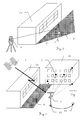
- a typical surveying task is under Using a positioning system shown.
- aim the survey is the positioning of various Points on an object 2c that is in a building group arranged together with a hall 2a and a building 2b is.
- a geodetic instrument 1 used that over the for each Surveying task necessary components.
- the Current position of this instrument 1, which for each current position to be determined for the survey purpose can represent, based on the signals of a Positioning system can be determined, this here purely exemplary as a satellite-based system Is accepted. From those of a satellite receiver of the Instruments 1 received, in a substantially straight line Spreading signals of the satellite 3 can the Derived from the current position.
- Fig.2 shows schematically the situation in the immediate of Near the object to be measured.
- a dead zone T is defined by the hall 2a, in which the reception of signals from the satellites 3 restricted or prevented.
- the survey of the Object can no longer be made from this dead zone T, because the actual position is no longer using the Positioning system can be determined. However, that is out of this dead zone T out the building 2b well visible.
- FIG. 3 A similar situation is shown in Fig. 3 for another one Variant of a positioning system shown.
- an instrument 1 ' whose position using a total station 4 is determined as Total Positioning System.
- a reflector To this Purpose carries the instrument instead of a satellite receiver a reflector, so from the on a known point positioned total station 4 from the direction and distance measured to the reflector. From this data, the Current position of the instrument 1 'are determined.
- similar way is the to Measurement of necessary visual connection between total station 4 and instrument 1 'through the hall 2a in certain Restricted or interrupted areas, so that likewise a dead zone T 'is formed.
- FIG 4 shows schematically the first step of a exemplary method according to the invention for the determination the current position.
- a first known position P1 out with the instrument 1 at least two Reference structures 5 on which also from the dead area T detectable building 2b detected and the distance to these Reference structures 5 measured.
- Reference structures 5 on which also from the dead area T detectable building 2b detected and the distance to these Reference structures 5 measured.
- reference points 5 In this example will be selected purely as reference points 5 as reference structures, however, especially by image processing methods also extended structures selected and in the further Steps can be compared with each other.
- the dead zone T itself located reference structures be selected, i. a measurement could be too according to the invention to a reference structure or a point take place at the hall 2a.
- the distance measurement takes place using the inclusion of an image in which the Distances are assigned to the reference structures 5.
- the first known position P1 may be the signals from satellites 3 are determined as these first known position P1 outside of the hall 2a dead zone T is located. After taking the Reference structures 5 with the associated image information and distances will be the instrument 1 to a second moved known position P2.
- the second known position P2 takes place from this second known position P2 from a second shot of the am Building 2b located reference structures 5 together with the associated image information and distances.
- This example is also the second known position P2 by the signals of the satellites 3 of a Determinable positioning system.
- the first known position P1 and / or the second known position P2 can be determined by other methods or be known in their position. in principle can also do one or both of the positions in the Dead zone T lie, but then the position must also determinable or known without positioning system.
- the capture of the reference structures 5 by an automatic Target tracking allows or facilitates.
- Fig. 6 shows schematically the determination of an actual position A with the aid of a first embodiment of the inventive method.
- the instrument 1 is located now in dead zone T. generated by the hall 2a In this dead zone T, the building 2b and at least a part of the reference structures 5 detected be so that on these reference structures 5 the Current position A can be determined.
- This provision is based in the first embodiment of the inventive method on the knowledge of actual position of the reference structures 5, wherein these are calculated from the image information and distances which are shown during the in Fig.4 and Fig.5 Steps were taken.
- the Actual position A becomes in the first two steps Similarly, the image information and removal of the Reference structures 5 added, so from the knowledge this data and the known position of the Reference structures 5, e.g.
- the Actual position can be determined.
- viewing in the image contained isolated reference structures 5 can doing an evaluation of the various image information also by a comprehensive comparison in the context of a Image processing, e.g. through suitable matching procedures, take place, with parallel a larger number of points is taken into account.
- Fig.7 schematically the determination of a Actual position A using a second embodiment of the inventive method explained.
- the instrument 1 is in the dead zone generated by the hall 2a T out of the building 2b and at least part of the Reference structures 5 can be detected.
- the determination the actual position A takes place in this second Embodiment of the inventive method by means of a transformation of the in Fig.4 and Fig.5 shown first known position P1 and second position P2 to the current position A.
- the Linking of these positions takes place via the Reference structures 5, for each Transformation matrices are derived.
- Such Transformation methods are for example from Photogrammetry known or derivable.
- This will be included this second embodiment of the inventive Procedure no real positions for the Reference structures 5 calculated so that in the calculation occurring errors can be avoided.
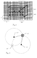
- Fig.8 shows purely exemplary of the inclusion of Reference structures and associated distances.
- a component for image acquisition for example a CD or CMOS camera, preferably with range imaging functionality
- the building 2b is captured in a picture 6 and this optionally stored.
- Picture 6 is from a larger number of pixels, wherein the Reference structures 5 in their extension only one or multiple pixels can be assigned.
- Reference structures are distance measurements performed, with both reference structures 5 and the measuring points of the distance measurement manually or can be determined automatically.
- suitable Structures are known methods of image processing available, such as Template matching and / or Neural Networks.
- the reference structure 5 assigned pixel from which then the Distance information for additional pixels can be extrapolated. In the example shown, too all five points covered as reference structures 5 Distance measurements are performed, the Distance to the respective middle (center of gravity) pixel or even all of the respective point Covered pixels are assigned equally can.
- Fig.9 purely by way of example the derivation of Image information from the inclusion of reference structures shown.
- the example shown here is only the principal explanation, since realized at Embodiments mainly higher developed methods image processing can be used advantageously, but what a purely manual handling is not excludes.
- the point- or structure-specific Distance information can be added from the recording Image information derived, for example, the Location in the picture or the relative arrangement of the Reference structures 5 with each other. For example, the location of the extreme left Point by a horizontal and vertical counting of the Pixels are determined. From the horizontal number X and The vertical number Y of pixels can be the location in the image as well as to a reference point, which here the lower left corner of the captured image section can be.
- the positions of the points to measure each other, as based on the Differences ⁇ X1, ⁇ Y1 and ⁇ Y2 of pixels between individual points is clarified. From the differences may be due to the existing distance measurements to the Points are also derived angles. This will be next to the Distance measurement also parallel information about the Arrangement of the reference structures to each other and opposite a reference point, which is used as image information with compared to the image information of further images can. It is not for a process according to the invention required to take full pictures or save. Relevant is a recording of Image information or image features that make a comparison with further recordings possible.
- Fig. 10 shows a greatly simplified, two-dimensional Example explaining the use of image information to resolve ambiguities in the Positioning.
- Reference structures 5 and 5 ' are two known for their position Reference structures 5 and 5 'are available.
- the distance is measured so that the actual position on a circle with the respective distance about the position of the respective Reference structure 5 and 5 'must be.
- a simultaneous Fulfillment of this condition is only due to the two Intersections of the circles before. Without further information It is not possible to decide which of them resulting and possible actual positions A 'or A " correct is.
- the schematic representation of a possible Embodiment of the inventive device or a geodetic instrument 1 according to the invention takes place in Fig.11.
- the geodetic instrument 1 has a Pole 7, which can be positioned exactly over a point is.
- a GPS receiver 8 for a satellite-based positioning system as Unit for position determination and a measuring unit 9 with a device for determining an actual position of the geodetic instrument 1.
- This device has an image pickup unit 10, an image and / or Image information memory 13, a rangefinder 12 and a data processing unit 14.
- the one of the Imaging unit 10 captured area becomes the user displayed on a touch-sensitive screen 11, the user surveying over this Screen can control.
- the Device optionally an inclinometer 15 and / or a Direction meter 16 have.
Priority Applications (9)
| Application Number | Priority Date | Filing Date | Title |
|---|---|---|---|
| EP03021133A EP1517116A1 (fr) | 2003-09-22 | 2003-09-22 | Méthode et appareil pour la détermination de la position actuelle d'un instrument géodésique |
| US10/595,189 US8077913B2 (en) | 2003-09-22 | 2004-09-09 | Method and device for determining the actual position of a geodetic instrument |
| JP2006526559A JP4646243B2 (ja) | 2003-09-22 | 2004-09-09 | 測地機器の現在位置を決定する方法と装置 |
| AT04764982T ATE532033T1 (de) | 2003-09-22 | 2004-09-09 | Verfahren und vorrichtung zur bestimmung der aktualposition eines geodätischen instrumentes |
| AU2004282274A AU2004282274B2 (en) | 2003-09-22 | 2004-09-09 | Method and device for determining the actual position of a geodetic instrument |
| EP04764982A EP1673589B1 (fr) | 2003-09-22 | 2004-09-09 | Procede et dispositif pour determiner la position courante d'un instrument geodesique |
| CNA2004800274824A CN1856692A (zh) | 2003-09-22 | 2004-09-09 | 用于对大地测量仪器的实际位置进行确定的方法和装置 |
| PCT/EP2004/010045 WO2005038395A1 (fr) | 2003-09-22 | 2004-09-09 | Procede et dispositif pour determiner la position courante d'un instrument geodesique |
| CA2539783A CA2539783C (fr) | 2003-09-22 | 2004-09-09 | Procede et dispositif pour determiner la position courante d'un instrument geodesique |
Applications Claiming Priority (1)
| Application Number | Priority Date | Filing Date | Title |
|---|---|---|---|
| EP03021133A EP1517116A1 (fr) | 2003-09-22 | 2003-09-22 | Méthode et appareil pour la détermination de la position actuelle d'un instrument géodésique |
Publications (1)
| Publication Number | Publication Date |
|---|---|
| EP1517116A1 true EP1517116A1 (fr) | 2005-03-23 |
Family
ID=34178436
Family Applications (2)
| Application Number | Title | Priority Date | Filing Date |
|---|---|---|---|
| EP03021133A Withdrawn EP1517116A1 (fr) | 2003-09-22 | 2003-09-22 | Méthode et appareil pour la détermination de la position actuelle d'un instrument géodésique |
| EP04764982A Active EP1673589B1 (fr) | 2003-09-22 | 2004-09-09 | Procede et dispositif pour determiner la position courante d'un instrument geodesique |
Family Applications After (1)
| Application Number | Title | Priority Date | Filing Date |
|---|---|---|---|
| EP04764982A Active EP1673589B1 (fr) | 2003-09-22 | 2004-09-09 | Procede et dispositif pour determiner la position courante d'un instrument geodesique |
Country Status (8)
| Country | Link |
|---|---|
| US (1) | US8077913B2 (fr) |
| EP (2) | EP1517116A1 (fr) |
| JP (1) | JP4646243B2 (fr) |
| CN (1) | CN1856692A (fr) |
| AT (1) | ATE532033T1 (fr) |
| AU (1) | AU2004282274B2 (fr) |
| CA (1) | CA2539783C (fr) |
| WO (1) | WO2005038395A1 (fr) |
Cited By (3)
| Publication number | Priority date | Publication date | Assignee | Title |
|---|---|---|---|---|
| CN103245336A (zh) * | 2013-05-20 | 2013-08-14 | 苏州大学 | 用于远度跳跃项目的距离测量装置 |
| EP3034995A1 (fr) * | 2014-12-19 | 2016-06-22 | Leica Geosystems AG | Procédé de détermination d'un décalage d'orientation ou de position d'un appareil de mesure géodésique et appareil de mesure correspondant |
| CN113222918A (zh) * | 2021-04-29 | 2021-08-06 | 桂林理工大学 | 多边形语义匹配检测高分辨率正射影像阴影方法 |
Families Citing this family (25)
| Publication number | Priority date | Publication date | Assignee | Title |
|---|---|---|---|---|
| AU2006263327B2 (en) * | 2005-06-27 | 2011-01-20 | Geo-Pioneers Ltd | Apparatus and method for evaluating data points against cadastral regulations |
| US7933001B2 (en) | 2005-07-11 | 2011-04-26 | Kabushiki Kaisha Topcon | Geographic data collecting system |
| JP4977339B2 (ja) * | 2005-07-11 | 2012-07-18 | 株式会社トプコン | 地理データ収集装置 |
| JP2008107085A (ja) * | 2006-10-23 | 2008-05-08 | Meidensha Corp | カメラ位置姿勢検出装置 |
| CN103398656B (zh) * | 2007-08-10 | 2016-08-10 | 莱卡地球系统公开股份有限公司 | 用于在物体表面上进行非接触坐标测量的方法和勘测系统 |
| US8396284B2 (en) * | 2007-10-23 | 2013-03-12 | Leica Geosystems Ag | Smart picking in 3D point clouds |
| JP5150307B2 (ja) * | 2008-03-03 | 2013-02-20 | 株式会社トプコン | 地理データ収集装置 |
| JP5150310B2 (ja) * | 2008-03-04 | 2013-02-20 | 株式会社トプコン | 地理データ収集装置 |
| JP5698480B2 (ja) | 2010-09-02 | 2015-04-08 | 株式会社トプコン | 測定方法及び測定装置 |
| US10168153B2 (en) | 2010-12-23 | 2019-01-01 | Trimble Inc. | Enhanced position measurement systems and methods |
| US9182229B2 (en) * | 2010-12-23 | 2015-11-10 | Trimble Navigation Limited | Enhanced position measurement systems and methods |
| US9879993B2 (en) | 2010-12-23 | 2018-01-30 | Trimble Inc. | Enhanced bundle adjustment techniques |
| EP2511658A1 (fr) | 2011-04-14 | 2012-10-17 | Hexagon Technology Center GmbH | Système de mesure et procédé de détermination de nouveau point |
| US9222771B2 (en) | 2011-10-17 | 2015-12-29 | Kla-Tencor Corp. | Acquisition of information for a construction site |
| US20130201210A1 (en) * | 2012-01-13 | 2013-08-08 | Qualcomm Incorporated | Virtual ruler |
| WO2014036774A1 (fr) * | 2012-09-06 | 2014-03-13 | 付建国 | Instrument de mesure de position multifonctionnel du type à interconnexion |
| DE102012217282B4 (de) * | 2012-09-25 | 2023-03-02 | Trimble Jena Gmbh | Verfahren und Vorrichtung zur Zuordnung von Messpunkten zu einem Satz von Festpunkten |
| US9235763B2 (en) | 2012-11-26 | 2016-01-12 | Trimble Navigation Limited | Integrated aerial photogrammetry surveys |
| US9247239B2 (en) | 2013-06-20 | 2016-01-26 | Trimble Navigation Limited | Use of overlap areas to optimize bundle adjustment |
| US9970757B2 (en) | 2014-01-08 | 2018-05-15 | Qualcomm Incorporated | Method and apparatus for positioning with always on barometer |
| CN104570006A (zh) * | 2015-01-29 | 2015-04-29 | 东南大学 | 一种基于Android移动终端的无死角定位系统及方法 |
| JP6332699B2 (ja) * | 2015-10-13 | 2018-05-30 | 株式会社amuse oneself | 測量用撮影装置 |
| CN106382876A (zh) * | 2016-11-24 | 2017-02-08 | 桂林理工大学 | 一种测量经纬仪仪器高度的简便方法 |
| US10586349B2 (en) | 2017-08-24 | 2020-03-10 | Trimble Inc. | Excavator bucket positioning via mobile device |
| US10943360B1 (en) | 2019-10-24 | 2021-03-09 | Trimble Inc. | Photogrammetric machine measure up |
Citations (4)
| Publication number | Priority date | Publication date | Assignee | Title |
|---|---|---|---|---|
| JPS6128814A (ja) * | 1984-07-19 | 1986-02-08 | Takao Yamaguchi | 構造物の内外壁を構成する点群の測量方法 |
| EP0587328A2 (fr) * | 1992-09-05 | 1994-03-16 | International Business Machines Corporation | Système de traitement d'images |
| FR2814539A3 (fr) * | 2000-09-27 | 2002-03-29 | Framatome Sa | Procede de releve et de trace a haute precision d'au moins une portion d'un circuit constitue de tuyauteries |
| US6381006B1 (en) * | 2000-07-12 | 2002-04-30 | Spectra Precision Ab | Spatial positioning |
Family Cites Families (23)
| Publication number | Priority date | Publication date | Assignee | Title |
|---|---|---|---|---|
| CH674898A5 (fr) * | 1988-07-06 | 1990-07-31 | Wild Leitz Ag | |
| CH677154A5 (fr) * | 1988-07-06 | 1991-04-15 | Wild Leitz Ag | |
| US5100229A (en) * | 1990-08-17 | 1992-03-31 | Spatial Positioning Systems, Inc. | Spatial positioning system |
| US5517419A (en) * | 1993-07-22 | 1996-05-14 | Synectics Corporation | Advanced terrain mapping system |
| US5396331A (en) * | 1993-08-10 | 1995-03-07 | Sanyo Machine Works, Ltd. | Method for executing three-dimensional measurement utilizing correctively computing the absolute positions of CCD cameras when image data vary |
| US6526352B1 (en) * | 2001-07-19 | 2003-02-25 | Intelligent Technologies International, Inc. | Method and arrangement for mapping a road |
| JPH09297021A (ja) * | 1996-05-07 | 1997-11-18 | Fujita Corp | 位置計測方法およびその装置 |
| US6741790B1 (en) * | 1997-05-29 | 2004-05-25 | Red Hen Systems, Inc. | GPS video mapping system |
| DE19743705C1 (de) * | 1997-10-02 | 1998-12-17 | Ibs Integrierte Business Syste | Verfahren zum Sammeln und Verknüpfen von Positionsdaten aus Satellitenortung und weiteren Daten sowie Verwendungen dafür |
| JP2000346634A (ja) * | 1999-06-09 | 2000-12-15 | Minolta Co Ltd | 3次元入力装置 |
| US6430505B1 (en) * | 2000-07-12 | 2002-08-06 | Trimble Navigation Limited | Automatic charting of obstructions for mission planning |
| JP4236372B2 (ja) * | 2000-09-25 | 2009-03-11 | インターナショナル・ビジネス・マシーンズ・コーポレーション | 空間情報利用システムおよびサーバシステム |
| KR100828226B1 (ko) * | 2000-12-26 | 2008-05-07 | 엘지전자 주식회사 | 이동 단말기의 위치 측정 시스템 및 방법 |
| JP4356050B2 (ja) * | 2000-12-28 | 2009-11-04 | 株式会社トプコン | 測量装置と電子的記憶媒体 |
| JP3437555B2 (ja) * | 2001-03-06 | 2003-08-18 | キヤノン株式会社 | 特定点検出方法及び装置 |
| EP1329690A1 (fr) * | 2002-01-22 | 2003-07-23 | Leica Geosystems AG | Procédé et dispositif pour la localisation automatique de cibles |
| FR2836215B1 (fr) * | 2002-02-21 | 2004-11-05 | Yodea | Systeme et procede de modelisation et de restitution tridimensionnelle d'un objet |
| JP4004316B2 (ja) * | 2002-03-20 | 2007-11-07 | 株式会社トプコン | 測量装置及び測量装置を用いて画像データを取得する方法 |
| US6762721B2 (en) * | 2002-10-12 | 2004-07-13 | Information Systems Laboratories, Inc. | Urban terrain geolocation system |
| WO2004042662A1 (fr) * | 2002-10-15 | 2004-05-21 | University Of Southern California | Environnements virtuels accrus |
| US20050057745A1 (en) * | 2003-09-17 | 2005-03-17 | Bontje Douglas A. | Measurement methods and apparatus |
| EP1681533A1 (fr) * | 2005-01-14 | 2006-07-19 | Leica Geosystems AG | Procédé et dispositif géodésique pour arpenter aux moins une cible |
| US7865285B2 (en) * | 2006-12-27 | 2011-01-04 | Caterpillar Inc | Machine control system and method |
-
2003
- 2003-09-22 EP EP03021133A patent/EP1517116A1/fr not_active Withdrawn
-
2004
- 2004-09-09 US US10/595,189 patent/US8077913B2/en active Active
- 2004-09-09 WO PCT/EP2004/010045 patent/WO2005038395A1/fr active Application Filing
- 2004-09-09 CN CNA2004800274824A patent/CN1856692A/zh active Pending
- 2004-09-09 EP EP04764982A patent/EP1673589B1/fr active Active
- 2004-09-09 JP JP2006526559A patent/JP4646243B2/ja not_active Expired - Fee Related
- 2004-09-09 AU AU2004282274A patent/AU2004282274B2/en not_active Ceased
- 2004-09-09 AT AT04764982T patent/ATE532033T1/de active
- 2004-09-09 CA CA2539783A patent/CA2539783C/fr not_active Expired - Fee Related
Patent Citations (4)
| Publication number | Priority date | Publication date | Assignee | Title |
|---|---|---|---|---|
| JPS6128814A (ja) * | 1984-07-19 | 1986-02-08 | Takao Yamaguchi | 構造物の内外壁を構成する点群の測量方法 |
| EP0587328A2 (fr) * | 1992-09-05 | 1994-03-16 | International Business Machines Corporation | Système de traitement d'images |
| US6381006B1 (en) * | 2000-07-12 | 2002-04-30 | Spectra Precision Ab | Spatial positioning |
| FR2814539A3 (fr) * | 2000-09-27 | 2002-03-29 | Framatome Sa | Procede de releve et de trace a haute precision d'au moins une portion d'un circuit constitue de tuyauteries |
Non-Patent Citations (1)
| Title |
|---|
| PATENT ABSTRACTS OF JAPAN vol. 010, no. 180 (P - 471) 24 June 1986 (1986-06-24) * |
Cited By (5)
| Publication number | Priority date | Publication date | Assignee | Title |
|---|---|---|---|---|
| CN103245336A (zh) * | 2013-05-20 | 2013-08-14 | 苏州大学 | 用于远度跳跃项目的距离测量装置 |
| CN103245336B (zh) * | 2013-05-20 | 2015-10-28 | 苏州大学 | 用于远度跳跃项目的距离测量装置 |
| EP3034995A1 (fr) * | 2014-12-19 | 2016-06-22 | Leica Geosystems AG | Procédé de détermination d'un décalage d'orientation ou de position d'un appareil de mesure géodésique et appareil de mesure correspondant |
| US10060739B2 (en) | 2014-12-19 | 2018-08-28 | Leica Geosystems Ag | Method for determining a position and orientation offset of a geodetic surveying device and such a surveying device |
| CN113222918A (zh) * | 2021-04-29 | 2021-08-06 | 桂林理工大学 | 多边形语义匹配检测高分辨率正射影像阴影方法 |
Also Published As
| Publication number | Publication date |
|---|---|
| CA2539783C (fr) | 2014-02-11 |
| CN1856692A (zh) | 2006-11-01 |
| EP1673589B1 (fr) | 2011-11-02 |
| AU2004282274A1 (en) | 2005-04-28 |
| AU2004282274B2 (en) | 2009-07-16 |
| CA2539783A1 (fr) | 2005-04-28 |
| WO2005038395A1 (fr) | 2005-04-28 |
| JP2007506076A (ja) | 2007-03-15 |
| ATE532033T1 (de) | 2011-11-15 |
| US20070133012A1 (en) | 2007-06-14 |
| JP4646243B2 (ja) | 2011-03-09 |
| US8077913B2 (en) | 2011-12-13 |
| EP1673589A1 (fr) | 2006-06-28 |
Similar Documents
| Publication | Publication Date | Title |
|---|---|---|
| EP1673589B1 (fr) | Procede et dispositif pour determiner la position courante d'un instrument geodesique | |
| EP1606581B1 (fr) | Procede et dispositif de traitement d'image d'un appareil de mesure geodesique | |
| DE10308525A1 (de) | Vermessungssystem | |
| EP1664674B1 (fr) | Méthode et système pour la détermination de la position actuelle d'un appareil de postionement portatif | |
| DE69836522T2 (de) | Lagenerkennungssystem eines selbstbewegenden Kraftwagens | |
| DE19528465C2 (de) | Verfahren und Vorrichtung zur schnellen Erfassung der Lage einer Zielmarke | |
| EP1836455B1 (fr) | Procede et appareil geodesique pour mesurer au moins une cible | |
| EP1062525B1 (fr) | Procede pour surveiller des objets ou un espace objet | |
| DE60034166T2 (de) | Automatische Vermessungsgerät und Verfahren zum dreidimensionalen Messen | |
| WO2017178190A1 (fr) | Procédé et système de détermination d'une position globale d'un premier repère | |
| CH695120A5 (de) | Anordnung und Verfahren zur Bestimmung der räumlichen Koordinaten mindestens eines Objekpunktes. | |
| WO2008009520A1 (fr) | Caméra de surveillance, procédé d'étalonnage et d'utilisation de la caméra de surveillance | |
| CH695121A5 (de) | Verfahren und Anordnung zur Durchführung von geodätischen Messungen mittels Videotachymeter. | |
| DE112005001307T5 (de) | Eingebaute Navigationsvorrichtung und Verfahren zur Koerrektur der eigenen Fahrzeugposition | |
| DE102006055652A1 (de) | Verfahren zur Aufarbeitung dreidimensionaler Daten und Vorrichtung zur Aufarbeitung dreidimensionaler Daten | |
| DE102014110992A1 (de) | Registrierung einer in Cluster zerfallenden Szene mit Standortverfolgung | |
| DE102014205640B4 (de) | Vermessung mittels mobilem Gerät | |
| DE10329341B4 (de) | Vermessungssystem | |
| EP0970392A1 (fr) | Procede de mesure utilisant la technique laser pour les objets tridimensionnels | |
| EP4051982A1 (fr) | Procédé et dispositif de détection mobile pour détecter des éléments d'infrastructure d'un réseau de conduits souterrains | |
| DE102010064480B3 (de) | Vorrichtung zur automatisierten Erfassung von Objekten mittels eines sich bewegenden Fahrzeugs | |
| DE4416557A1 (de) | Verfahren und Vorrichtung zur Stützung der Trägheitsnavigation eines ein entferntes Ziel autonom ansteuernden Flugkörpers | |
| DE102004028736A1 (de) | Verfahren zur automatischen Erfassung und Bestimmung von ortsfesten Objekten im Freien von einem fahrenden Fahrzeug aus | |
| EP3008636A1 (fr) | Procédé et système de détection, par un véhicule, d'une ou de plusieurs personnes | |
| WO2002101328A1 (fr) | Procede pour detecter la surface d'une voie de circulation |
Legal Events
| Date | Code | Title | Description |
|---|---|---|---|
| PUAI | Public reference made under article 153(3) epc to a published international application that has entered the european phase |
Free format text: ORIGINAL CODE: 0009012 |
|
| AK | Designated contracting states |
Kind code of ref document: A1 Designated state(s): AT BE BG CH CY CZ DE DK EE ES FI FR GB GR HU IE IT LI LU MC NL PT RO SE SI SK TR |
|
| AX | Request for extension of the european patent |
Extension state: AL LT LV MK |
|
| AKX | Designation fees paid | ||
| REG | Reference to a national code |
Ref country code: DE Ref legal event code: 8566 |
|
| STAA | Information on the status of an ep patent application or granted ep patent |
Free format text: STATUS: THE APPLICATION IS DEEMED TO BE WITHDRAWN |
|
| 18D | Application deemed to be withdrawn |
Effective date: 20050924 |