EP1517116A1 - Method and device for the determination of the actual position of a geodesic instrument - Google Patents
Method and device for the determination of the actual position of a geodesic instrument Download PDFInfo
- Publication number
- EP1517116A1 EP1517116A1 EP03021133A EP03021133A EP1517116A1 EP 1517116 A1 EP1517116 A1 EP 1517116A1 EP 03021133 A EP03021133 A EP 03021133A EP 03021133 A EP03021133 A EP 03021133A EP 1517116 A1 EP1517116 A1 EP 1517116A1
- Authority
- EP
- European Patent Office
- Prior art keywords
- image information
- actual position
- positioning system
- reference structures
- distance
- Prior art date
- Legal status (The legal status is an assumption and is not a legal conclusion. Google has not performed a legal analysis and makes no representation as to the accuracy of the status listed.)
- Withdrawn
Links
Images


Classifications
-
- G—PHYSICS
- G01—MEASURING; TESTING
- G01C—MEASURING DISTANCES, LEVELS OR BEARINGS; SURVEYING; NAVIGATION; GYROSCOPIC INSTRUMENTS; PHOTOGRAMMETRY OR VIDEOGRAMMETRY
- G01C11/00—Photogrammetry or videogrammetry, e.g. stereogrammetry; Photographic surveying
- G01C11/02—Picture taking arrangements specially adapted for photogrammetry or photographic surveying, e.g. controlling overlapping of pictures
-
- G—PHYSICS
- G01—MEASURING; TESTING
- G01C—MEASURING DISTANCES, LEVELS OR BEARINGS; SURVEYING; NAVIGATION; GYROSCOPIC INSTRUMENTS; PHOTOGRAMMETRY OR VIDEOGRAMMETRY
- G01C15/00—Surveying instruments or accessories not provided for in groups G01C1/00 - G01C13/00
Definitions
- the invention relates to a method for determining the Actual position of a geodetic instrument Claim 1, an apparatus for performing this Method according to the preamble of claim 14, a geodetic instrument with such a device after Claim 19 and a computer program product according to claim 20th
- a direction and distance measurement with the Tachymeter to the geodesic instrument may be included known position of the tachymeter and the position of the Instruments are determined. Prerequisite for the measurement Here is the line of sight between the two Components. If this connection is interrupted, e.g. by vegetation or buildings in the field of vision, failed the type of position determination.
- a geodetic instrument only has via a capacity for distance measurement or a Measuring angles is not the required precision or speed. In these cases must the position determination solely by distance measurements be performed. For this the distances become too measured several points with known position and with known methods, as for example in the Photogrammetry can be used, an example of this represent correlation methods or correlation calculations , the determination of the actual position can take place. There is the number of points needed depending on their location and the intended accuracy of the measurement. in the As a rule, however, apart from particularly favorable Constellations, at least 3 or 4 points needed. Becomes additionally taking account of an angle, e.g. in addition the angle relative to the horizontal can be detected the number of points will be reduced.
- the surveying equipment has one Receiver for a satellite position measuring system and one, preferably electro-optical or on the Ultrasonic principle based distance meter. Both Components are mounted on a pole, which with its pole tip can be precisely positioned and via an inclinometer as well as an indicator of vertical Alignment features. Optionally, one can also be added to the Earth magnetic field reacting sensor be present. By at least 2 measurements to a point of 2 different known positions, e.g. by the satellite position measurement system can be determined now the position of this point can be determined, even if this is within the dead zone.
- An object of the present invention is to provide for a determination of the actual position in one shaded area necessary number of reference points and / or measurements to determine the position of these To reduce reference points.
- Another task is simplification and shortening the measurements for the determination of reference points and Actual position.
- Another object of the invention is to provide a automatic identification and measurement of To allow reference points.
- the invention relates to a method and a device for determining the actual position of a geodesic Instrument.
- a device in an area in which shadable signals of a Positioning system can be received at least two positions distance measurements to each made at least two reference points. With these Distances are linked additionally image information received by the device. These can be out complete images of a captured field of view or but for example from sub-images or sections consist. The measured distances are measured with the Image information linked or contained in this Assigned reference structures. These reference structures In the simplest case you can score points, but also bigger ones or more more complex structures. Set suitable points e.g. well identifiable transitions, edges or intersections of lines, such as window corners or Window crosses dar.
- image information includes in particular the arrangement relationship for individual points. These points are according to the invention usually with Distance measurements used as reference structures Be linked to objects, these distance measurements each of the physical pixels of a receiver be assigned, which represent the object or to whose image belongs to the recipient. From the mutual arrangement of the distance measurements can then again a logical assignment of distance and Reference point are derived. Under image information should here in particular the mutual arrangement or Orientation of distance measurements are understood at the same time to all pixels of a captured Field of view done. There is no longer a picture necessarily from the inclusion of textures or Surfaces, but can also be made exclusively related to each other, in particular geometrically arranged, distance measurements exist.
- Range Imaging delivers one two-dimensional arrangement of distance measurements and thus a kind of three-dimensional image or a topography of the detected field of view or measuring field.
- the measurements can but also a normal, texture-capturing image be assigned.
- Brightness and distance are recorded, so for any image information, for example, from the location of a physical pixel on the receiver, just These brightness values and distances are available.
- the arrangement of a distance measurement can also be used relative to other range measurements, so that also on the knowledge of the absolute position of a pixel can be waived on the recipient. This can For example, for a complete evaluation of the with the Receivers recorded field of view are waived so that e.g. higher with subwindowing or subframing Achieve processing speeds.
- a manual Distance measurement to selected points in a picture respectively.
- suitable methods and devices for manually controlled measurement of points in one captured image are for example from EP 1 314 940 A1 known.
- the electronic display and described therein Control device allows the selection of points in one Image to which measurements can be taken without that a movement of the optical axis must take place.
- By the manual selection of points and their sequential, if necessary automatic measurement will be Distance and Picture information of the different points linked.
- this information can well-known methods of photogrammetry and the Image processing can be used.
- the degrees of freedom are limited. That With every known position from which it is measured a further or more precise determination of the spatial positions of the reference structures.
- the combination of image and Distance information offers over sequential ones Measuring individual points a lot of advantages. Due to the simultaneous or timely recording and pictorial arrangement of the measurements Association problems avoided. In addition, already offers the detection of the spatial arrangement or sequence of Measurements additional information to the following Determining the current position can be used.
- CMOS sensors be used, which is a subwindowing or the definition a specific area of interest (Region of Interest) allow for image capture.
- the Actual position After taking the picture and distance information from the two known positions can the Actual position also be determined in the dead zone. For this In turn, a recording and measurement is performed at a viewing area must be detected, at least contains two of the reference structures. From the knowledge of Reference structures can be on the actual position be deduced, e.g. through a Resection procedures. For this, the actual Positions of the reference structures have been derived.
- a possibility of completely automated Implementation of the method with an embodiment of the inventive device allows the measurement in Areas corresponding to the signals of the positioning system accessible or shaded, without special Taking into account the limit of these areas during the Measurement.
- the device is designed that during the surveying process with their Detection area always roughly on a clearly visible Area is aligned. It will automatically and consecutive images of this area along with the recorded measured distances.
- the identification of Reference points in the detection area or in the images via image processing and automatically.
- continuous recordings are different Go through points whose position through the Positioning system to be determined or their position anyway known, e.g. since it was measured in advance or trigonometric points.
- geometric instrument is intended in this Generalizing always a measuring instrument or an instrument associated with geodesic Measurements is used, such as a pole, understood this being used to measure or verify data with spatial reference serves. In particular, this concerns the Measurement of distance and / or direction or angles to a reference or measuring point. In addition, however, can still other devices, e.g. Components for Image capture or communication with others System components that exist for complementary Measurements or data recordings can be used.
- theodolites and so-called total stations as a tachymeter with electronic angle measurement and be understood electro-optical rangefinder.
- the invention is for use in specialized devices with similar functionality suitable, e.g. in military Richt Vietnamese or in the industrial construction or process monitoring; these Systems are also covered by the term "geodetic instrument”.
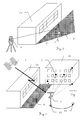
- a typical surveying task is under Using a positioning system shown.
- aim the survey is the positioning of various Points on an object 2c that is in a building group arranged together with a hall 2a and a building 2b is.
- a geodetic instrument 1 used that over the for each Surveying task necessary components.
- the Current position of this instrument 1, which for each current position to be determined for the survey purpose can represent, based on the signals of a Positioning system can be determined, this here purely exemplary as a satellite-based system Is accepted. From those of a satellite receiver of the Instruments 1 received, in a substantially straight line Spreading signals of the satellite 3 can the Derived from the current position.
- Fig.2 shows schematically the situation in the immediate of Near the object to be measured.
- a dead zone T is defined by the hall 2a, in which the reception of signals from the satellites 3 restricted or prevented.
- the survey of the Object can no longer be made from this dead zone T, because the actual position is no longer using the Positioning system can be determined. However, that is out of this dead zone T out the building 2b well visible.
- FIG. 3 A similar situation is shown in Fig. 3 for another one Variant of a positioning system shown.
- an instrument 1 ' whose position using a total station 4 is determined as Total Positioning System.
- a reflector To this Purpose carries the instrument instead of a satellite receiver a reflector, so from the on a known point positioned total station 4 from the direction and distance measured to the reflector. From this data, the Current position of the instrument 1 'are determined.
- similar way is the to Measurement of necessary visual connection between total station 4 and instrument 1 'through the hall 2a in certain Restricted or interrupted areas, so that likewise a dead zone T 'is formed.
- FIG 4 shows schematically the first step of a exemplary method according to the invention for the determination the current position.
- a first known position P1 out with the instrument 1 at least two Reference structures 5 on which also from the dead area T detectable building 2b detected and the distance to these Reference structures 5 measured.
- Reference structures 5 on which also from the dead area T detectable building 2b detected and the distance to these Reference structures 5 measured.
- reference points 5 In this example will be selected purely as reference points 5 as reference structures, however, especially by image processing methods also extended structures selected and in the further Steps can be compared with each other.
- the dead zone T itself located reference structures be selected, i. a measurement could be too according to the invention to a reference structure or a point take place at the hall 2a.
- the distance measurement takes place using the inclusion of an image in which the Distances are assigned to the reference structures 5.
- the first known position P1 may be the signals from satellites 3 are determined as these first known position P1 outside of the hall 2a dead zone T is located. After taking the Reference structures 5 with the associated image information and distances will be the instrument 1 to a second moved known position P2.
- the second known position P2 takes place from this second known position P2 from a second shot of the am Building 2b located reference structures 5 together with the associated image information and distances.
- This example is also the second known position P2 by the signals of the satellites 3 of a Determinable positioning system.
- the first known position P1 and / or the second known position P2 can be determined by other methods or be known in their position. in principle can also do one or both of the positions in the Dead zone T lie, but then the position must also determinable or known without positioning system.
- the capture of the reference structures 5 by an automatic Target tracking allows or facilitates.
- Fig. 6 shows schematically the determination of an actual position A with the aid of a first embodiment of the inventive method.
- the instrument 1 is located now in dead zone T. generated by the hall 2a In this dead zone T, the building 2b and at least a part of the reference structures 5 detected be so that on these reference structures 5 the Current position A can be determined.
- This provision is based in the first embodiment of the inventive method on the knowledge of actual position of the reference structures 5, wherein these are calculated from the image information and distances which are shown during the in Fig.4 and Fig.5 Steps were taken.
- the Actual position A becomes in the first two steps Similarly, the image information and removal of the Reference structures 5 added, so from the knowledge this data and the known position of the Reference structures 5, e.g.
- the Actual position can be determined.
- viewing in the image contained isolated reference structures 5 can doing an evaluation of the various image information also by a comprehensive comparison in the context of a Image processing, e.g. through suitable matching procedures, take place, with parallel a larger number of points is taken into account.
- Fig.7 schematically the determination of a Actual position A using a second embodiment of the inventive method explained.
- the instrument 1 is in the dead zone generated by the hall 2a T out of the building 2b and at least part of the Reference structures 5 can be detected.
- the determination the actual position A takes place in this second Embodiment of the inventive method by means of a transformation of the in Fig.4 and Fig.5 shown first known position P1 and second position P2 to the current position A.
- the Linking of these positions takes place via the Reference structures 5, for each Transformation matrices are derived.
- Such Transformation methods are for example from Photogrammetry known or derivable.
- This will be included this second embodiment of the inventive Procedure no real positions for the Reference structures 5 calculated so that in the calculation occurring errors can be avoided.
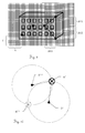
- Fig.8 shows purely exemplary of the inclusion of Reference structures and associated distances.
- a component for image acquisition for example a CD or CMOS camera, preferably with range imaging functionality
- the building 2b is captured in a picture 6 and this optionally stored.
- Picture 6 is from a larger number of pixels, wherein the Reference structures 5 in their extension only one or multiple pixels can be assigned.
- Reference structures are distance measurements performed, with both reference structures 5 and the measuring points of the distance measurement manually or can be determined automatically.
- suitable Structures are known methods of image processing available, such as Template matching and / or Neural Networks.
- the reference structure 5 assigned pixel from which then the Distance information for additional pixels can be extrapolated. In the example shown, too all five points covered as reference structures 5 Distance measurements are performed, the Distance to the respective middle (center of gravity) pixel or even all of the respective point Covered pixels are assigned equally can.
- Fig.9 purely by way of example the derivation of Image information from the inclusion of reference structures shown.
- the example shown here is only the principal explanation, since realized at Embodiments mainly higher developed methods image processing can be used advantageously, but what a purely manual handling is not excludes.
- the point- or structure-specific Distance information can be added from the recording Image information derived, for example, the Location in the picture or the relative arrangement of the Reference structures 5 with each other. For example, the location of the extreme left Point by a horizontal and vertical counting of the Pixels are determined. From the horizontal number X and The vertical number Y of pixels can be the location in the image as well as to a reference point, which here the lower left corner of the captured image section can be.
- the positions of the points to measure each other, as based on the Differences ⁇ X1, ⁇ Y1 and ⁇ Y2 of pixels between individual points is clarified. From the differences may be due to the existing distance measurements to the Points are also derived angles. This will be next to the Distance measurement also parallel information about the Arrangement of the reference structures to each other and opposite a reference point, which is used as image information with compared to the image information of further images can. It is not for a process according to the invention required to take full pictures or save. Relevant is a recording of Image information or image features that make a comparison with further recordings possible.
- Fig. 10 shows a greatly simplified, two-dimensional Example explaining the use of image information to resolve ambiguities in the Positioning.
- Reference structures 5 and 5 ' are two known for their position Reference structures 5 and 5 'are available.
- the distance is measured so that the actual position on a circle with the respective distance about the position of the respective Reference structure 5 and 5 'must be.
- a simultaneous Fulfillment of this condition is only due to the two Intersections of the circles before. Without further information It is not possible to decide which of them resulting and possible actual positions A 'or A " correct is.
- the schematic representation of a possible Embodiment of the inventive device or a geodetic instrument 1 according to the invention takes place in Fig.11.
- the geodetic instrument 1 has a Pole 7, which can be positioned exactly over a point is.
- a GPS receiver 8 for a satellite-based positioning system as Unit for position determination and a measuring unit 9 with a device for determining an actual position of the geodetic instrument 1.
- This device has an image pickup unit 10, an image and / or Image information memory 13, a rangefinder 12 and a data processing unit 14.
- the one of the Imaging unit 10 captured area becomes the user displayed on a touch-sensitive screen 11, the user surveying over this Screen can control.
- the Device optionally an inclinometer 15 and / or a Direction meter 16 have.
Abstract
Description
Die Erfindung betrifft ein Verfahren zur Bestimmung der
Aktualposition eines geodätischen Instrumentes nach
Anspruch 1, eine Vorrichtung zur Durchführung dieses
Verfahrens nach dem Oberbegriff des Anspruchs 14, ein
geodätisches Instrument mit einer solchen Vorrichtung nach
Anspruch 19 sowie ein Computerprogrammprodukt nach Anspruch
20.The invention relates to a method for determining the
Actual position of a
In vielen geodätischen Anwendungen werden Verfahren und Systeme zur Positionsbestimmung eines geodätischen Instrumentes verwendet, die auf der Ausbreitung von Signalen beruhen, die abgeschattet werde können und somit in ihrer Nutzbarkeit eingeschränkt werden. Ein Beispiel für solche Positionsbestimmungssysteme sind globale Positionierungssysteme wie z.B. GPS, GLONASS oder das im Aufbau befindliche europäische Galileo-System. Diese Systeme basieren auf dem möglichst ungestörten Empfang von Satellitensignalen. Im unmittelbaren Nahbereich von Hindernissen kann aufgrund deren abschattender Wirkung der Empfang der Signale eingeschränkt oder vollständig unmöglich sein, so dass eine Positionsbestimmung mit diesem System nicht mehr möglich ist. Ein weiteres Beispiel stellt die Positionsbestimmung eines reflektortragenden Instrumentes mit einem Theodoliten bzw. Tachymeter dar. Durch eine Richtungs- und Entfernungsmessung mit dem Tachymeter zu dem geodätischen Instrument kann bei bekannter Position des Tachymeters auch die Position des Instruments bestimmt werden. Voraussetzung für die Messung ist hier die Sichtverbindung zwischen den beiden Komponenten. Erfolgt eine Unterbrechung dieser Verbindung, z.B. durch Bewuchs oder Gebäude im Sichtbereich, versagt die Art der Positionsbestimmung.In many geodetic applications, procedures and Systems for determining the position of a geodesic Instrumentes used on the spread of Signals are based, which can be shaded and thus be limited in their usability. An example for such positioning systems are global Positioning systems such as e.g. GPS, GLONASS or the im Building European Galileo system. These Systems are based on the most undisturbed reception of Satellite signals. In the immediate vicinity of Obstacles may be due to their shading effect of Reception of the signals limited or complete be impossible, so do a positioning with this System is no longer possible. Another example presents the position determination of a reflector-bearing Instrument with a theodolite or tachymeter dar. By a direction and distance measurement with the Tachymeter to the geodesic instrument may be included known position of the tachymeter and the position of the Instruments are determined. Prerequisite for the measurement Here is the line of sight between the two Components. If this connection is interrupted, e.g. by vegetation or buildings in the field of vision, failed the type of position determination.
Um eine Positionsbestimmung der Aktualposition, also des gegenwärtigen Standortes des Instruments, auch in einem solcherart abgeschatteten Totbereich zu ermöglichen, sind Verfahren bekannt, die auf einer Bestimmung der eigenen Position gegenüber hinsichtlich ihrer Position bekannten Objekten beruhen. Ein Beispiel hierfür stellt das klassische Verfahren des Rückwärtsschnittes dar.To a position determination of the current position, so the current location of the instrument, also in one Such a shadowed dead area to allow are Methods are known which are based on a determination of their own Position opposite known with respect to their position Based on objects. An example of this is the classical method of backward cutting dar.
In vielen Fällen verfügt ein geodätisches Instrument nur über eine Fähigkeit zur Entfernungsmessung bzw. eine Messung von Winkeln ist nicht mit der benötigten Präzision oder Geschwindigkeit durchzuführen. In diesen Fällen muss die Positionsbestimmung allein durch Entfernungsmessungen durchgeführt werden. Hierzu werden die Entfernungen zu mehreren Punkten mit bekannter Position gemessen und mit bekannten Verfahren, wie sie beispielsweise auch in der Photogrammetrie verwendet werden, ein Beispiel hierfür stellen Korrelationsverfahren bzw. Korrelationsrechnungen dar, kann die Bestimmung der Aktualposition erfolgen. Dabei ist die Zahl der benötigen Punkte abhängig von deren Lage und der beabsichtigten Genauigkeit der Messung. Im Regelfall werden aber, abgesehen von besonders günstigen Konstellationen, mindestens 3 oder 4 Punkte benötigt. Wird zusätzlich ein Winkel berücksichtigt, z.B. indem zusätzlich der Winkel gegenüber der Horizontalen erfasst wird, kann die Zahl der Punkte reduziert werden.In many cases, a geodetic instrument only has via a capacity for distance measurement or a Measuring angles is not the required precision or speed. In these cases must the position determination solely by distance measurements be performed. For this the distances become too measured several points with known position and with known methods, as for example in the Photogrammetry can be used, an example of this represent correlation methods or correlation calculations , the determination of the actual position can take place. there is the number of points needed depending on their location and the intended accuracy of the measurement. in the As a rule, however, apart from particularly favorable Constellations, at least 3 or 4 points needed. Becomes additionally taking account of an angle, e.g. in addition the angle relative to the horizontal can be detected the number of points will be reduced.
Um nun mit einem rein entfernungsmessenden Verfahren auch Positionen im Totbereich zur Vermessung verwenden zu können, ist zuerst nötig, von bekannten Standorten aus die später zur Referenzierung benötigten Referenzpunkte zu vermessen.So now with a purely distance-measuring method too Use positions in the dead zone for surveying First, it is necessary, from known locations later needed for referencing reference points too measure.
Ein hierfür geeignetes Vermessungsgerät wird beispielsweise in der europäischen Patentschrift EP 0 403 585 B1 beschrieben. Das Vermessungsgerät verfügt über einen Empfänger für ein Satelliten-Positionsmess-System und einen, vorzugsweise elektrooptischen oder auf dem Ultraschallprinzip beruhenden Distanzmesser. Beide Komponenten sind auf einem Lotstock angebracht, der mit seiner Lotstabspitze präzise positioniert werden kann und über einen Neigungsmesser sowie eine Anzeige der vertikalen Ausrichtung verfügt. Optional kann auch ein auf das Erdmagnetfeld reagierender Sensor vorhanden sein. Durch mindestens 2 Messungen zu einem Punkt von 2 unterschiedlichen bekannten Positionen aus, die z.B. durch das Satelliten-Positionsmess-System bestimmt werden, kann nun die Position dieses Punkts bestimmt werden, auch wenn dieser innerhalb des Totbereichs liegt.A suitable for surveying device, for example in European Patent EP 0 403 585 B1 described. The surveying equipment has one Receiver for a satellite position measuring system and one, preferably electro-optical or on the Ultrasonic principle based distance meter. Both Components are mounted on a pole, which with its pole tip can be precisely positioned and via an inclinometer as well as an indicator of vertical Alignment features. Optionally, one can also be added to the Earth magnetic field reacting sensor be present. By at least 2 measurements to a point of 2 different known positions, e.g. by the satellite position measurement system can be determined now the position of this point can be determined, even if this is within the dead zone.
Umgekehrt kann auch die Position eines solchen Vermessungsgeräts im Totbereich durch Messungen zu mehreren bekannten Punkten im Rückwärtsschnittverfahren bestimmt werden.Conversely, the position of such a Surveyor in the dead zone by measurements to several determined points in the backward cutting method become.
Sollen nun im Rahmen einer Vermessung Vermessungspositionen für das geodätische Instrument sowohl in vom Positionierungssystem erfassten Räumen als auch in Totbereichen verwendet werden, so ist es notwendig, vor Nutzung des Totbereichs entsprechende Referenzpunkte für eine spätere Bestimmung der Aktualposition im Totbereich zu vermessen. Soll auf eine explizite Winkelmessung verzichtet werden, müssen im Regelfall mindestens für drei bis vier Punkte von mindestens drei bis vier bekannten Positionen aus die Entfernungen gemessen werden, um eine eindeutige Positionsbestimmung zu ermöglichen. Die jeweils tatsächlich benötigte Zahl an Punkten ist abhängig von der Lage der bekannten Punkten und ggf. möglicher Einschränkungen zur Reduzierung einer Mehrdeutigkeit. Bei drei Entfernungsmessungen zu einem Punkt wird durch die drei bekannten Punkte eine Ebene definiert, an der die zu bestimmende Position gespiegelt werden kann. Als Lösung ergeben sich zwei mögliche Positionen, von denen aber meist eine Position aus Plausibilitätsgründen, z.B. weil sie unter der Erdoberfläche liegen würde, oder aufgrund einfacher weiterer Informationen ausgeschlossen werden kann, wie z.B. der Unterscheidung zwischen Nord und Süd, die auch durch einen einfachen Magnetkompass getroffen werden kann. Eine eindeutige Bestimmung mit drei bekannten Punkten ist möglich, wenn günstige geometrische Verhältnisse vorliegen. Dies ist beispielsweise der Fall, wenn die gesuchte Position auf einer Verbindungsgeraden zwischen zwei bekannten Punkten liegt.Should now in the context of a survey surveying positions for the geodesic instrument both in the Positioning system covered spaces as well Dead areas are used, so it is necessary before Use of dead zone corresponding reference points for a later determination of the actual position in the dead zone measure. Should waive an explicit angle measurement usually, at least for three to four Points of at least three to four known positions from the distances to be measured to a unique To enable position determination. The each actually required number of points depends on the location of the known points and possibly possible restrictions Reduction of ambiguity. At three Distance measurements to a point is made by the three known points defines a plane at which the determining position can be mirrored. As a solution arise two possible positions, of which but mostly a position for reasons of plausibility, e.g. because they would lie beneath the earth's surface, or due simple further information can be excluded can, for example the distinction between North and South, which also hit by a simple magnetic compass can be. A unique determination with three known Points is possible if favorable geometric Conditions exist. This is the case for example if the searched position is on a connecting line lies between two known points.
Je nach den Gegebenheiten einer Messung müssen somit mindestens zwischen 9 und 16 Entfernungsmessungen durchgeführt werden, bei denen jeweils eine korrekte Zuordnung von Messung zu Referenzpunkt und bekannter Position erfolgen muss. Eine manuelle Durchführung solcher Messungen bedingt damit einen hohen Handhabungsaufwand und eine fehlererzeugende Komplexität.Depending on the circumstances of a measurement must thus at least between 9 and 16 distance measurements be carried out, each with a correct Assignment of measurement to reference point and known Position must occur. A manual implementation of such Measurements thus requires a high handling effort and an error-generating complexity.
Darüber hinaus müssen zur Erzielung einer hinreichenden Genauigkeit der Positionsbestimmung aufgrund ihrer geometrischen Anordnung geeignete Referenzpunkte gewählt werden. Auch der bewusst zu vollziehende Positionswechsel zwischen den bekannten Positionen wirkt sich störend auf den Messvorgang aus. Schliesslich ist mit solchen Verfahren des Stands der Technik stets die Ausdehnung der vom Positionierungssystem erfassten und abgeschatteten Bereiche aktiv zu beobachten, um rechtzeitig einen Wechsel des zu verwendenden Positionierungsverfahrens durchführen zu können.In addition, to achieve a sufficient Accuracy of positioning due to their geometrical arrangement selected suitable reference points become. Also the deliberate change of position between the known positions has a disturbing effect the measuring process. Finally, with such procedures the state of the art always the extent of the Positioning system covered and shaded areas actively watching to change in a timely manner perform the positioning procedure can.
Eine Aufgabe der vorliegenden Erfindung besteht darin, die für eine Bestimmung der Aktualposition in einem abgeschatteten Bereich notwendige Zahl von Referenzpunkten und/oder von Messungen zur Bestimmung der Position dieser Referenzpunkte zu verringern.An object of the present invention is to provide for a determination of the actual position in one shaded area necessary number of reference points and / or measurements to determine the position of these To reduce reference points.
Die Erhöhung der Positionsgenauigkeit bei der Bestimmung einer Aktualposition in einem abgeschatteten Bereich ist eine weitere Aufgabe der vorliegenden Erfindung.The increase of the position accuracy in the determination an actual position in a shaded area another object of the present invention.
Eine weitere Aufgabe ist die Vereinfachung und Verkürzung der Messungen zur Bestimmung von Referenzpunkten und Aktualposition.Another task is simplification and shortening the measurements for the determination of reference points and Actual position.
Eine weitere Aufgabe der Erfindung besteht darin, eine automatische Identifizierung und Vermessung der Referenzpunkte zu ermöglichen.Another object of the invention is to provide a automatic identification and measurement of To allow reference points.
Schliesslich ist die Automatisierung der Positionsbestimmung und des automatisierten Wechsels zwischen den jeweils hierfür geeigneten Verfahren eine weitere Aufgabe der vorliegenden Erfindung.Finally, the automation of Positioning and automated change between the appropriate procedures one Another object of the present invention.
Diese Aufgaben werden erfindungsgemäss durch Merkmale der
Ansprüche 1, 14 bzw. 19 oder durch Merkmale der Unteransprüche
gelöst. These objects are achieved according to the invention by features of
Die Erfindung betrifft ein Verfahren und eine Vorrichtung zur Bestimmung der Aktualposition eines geodätischen Instrumentes. Hierfür werden durch eine Vorrichtung in einem Bereich, in dem abschattbare Signale eines Positionierungssystems empfangen werden können, an mindestens zwei Positionen Entfernungsmessungen zu jeweils mindestens zwei Referenzpunkten vorgenommen. Mit diesen Entfernungen verknüpft werden zusätzlich Bildinformationen durch die Vorrichtung aufgenommen. Diese können aus vollständigen Bildern eines erfassten Sichtbereichs oder aber beispielsweise aus Teilbildern oder Ausschnitten bestehen. Die gemessenen Entfernungen werden mit der Bildinformation verknüpften bzw. in dieser enthaltenen Referenzstrukturen zugeordnet. Diese Referenzstrukturen können im einfachsten Fall Punkte, aber auch grössere oder komplexere Strukturen, darstellen. Geeignete Punkte stellen z.B. gut identifizierbare Übergänge, Kanten oder Kreuzungen von Linien, wie beispielsweise Fensterecken oder Fensterkreuze dar. Der Begriff Bildinformation beinhaltet insbesondere die Anordnungsbeziehung für einzelne Punkte. Diese Punkte werden erfindungsgemäss meist mit Entfernungsmessungen zu als Referenzstrukturen verwendeten Objekten verknüpft sein, wobei diese Entfernungsmessungen jeweils den physikalischen Bildpunkten eines Empfängers zugeordnet werden, die das Objekt repräsentieren bzw. zu dessen Abbild auf dem Empfänger gehören. Aus der gegenseitigen Anordnung der Entfernungsmessungen kann dann wiederum eine logische Zuordnung von Entfernung und Referenzpunkt abgeleitet werden. Unter Bildinformation soll hier insbesondere auch die gegenseitige Anordnung oder Orientierung von Entfernungsmessungen verstanden werden, die gleichzeitig zu allen Bildpunkten eines erfassten Sichtbereichs erfolgen. Damit besteht ein Bild nicht mehr notwendigerweise aus der Aufnahme von Texturen bzw. Oberflächen, sondern kann auch ausschliesslich aus miteinander in Bezug gesetzten, insbesondere geometrisch angeordneten, Entfernungsmessungen bestehen. Ein solches Range Imaging liefert damit beispielsweise eine zweidimensionale Anordnung von Entfernungsmessungen und damit eine Art dreidimensionales Bild bzw. eine Topographie des erfassten Sicht- bzw. Messfeldes. Die Messungen können jedoch auch einem normalen, Textur-erfassenden Bild zugeordnet sein. Beispielsweise können für jeden Bildpunkt Helligkeit und Entfernung aufgenommen werden, so dass für jede Bildinformation, die beispielsweise aus der Lage eines physikalischen Bildpunktes auf dem Empfänger besteht, eben diese Helligkeitswerte und Entfernungen verfügbar sind. Jedoch kann auch die Anordnung einer Entfernungsmessung relativ zu anderen Entfernungsmessungen erfolgen, so dass auch auf die Kenntnis der absoluten Lage eines Bildpunktes auf dem Empfänger verzichtet werden kann. Hierdurch kann beispielsweise auf eine vollständige Auswertung des mit dem Empfänger erfassten Sichtbereichs verzichtet werden, so dass sich z.B. mit Subwindowing oder Subframing höhere Verarbeitungsgeschwindigkeiten realisieren lassen.The invention relates to a method and a device for determining the actual position of a geodesic Instrument. For this purpose, a device in an area in which shadable signals of a Positioning system can be received at least two positions distance measurements to each made at least two reference points. With these Distances are linked additionally image information received by the device. These can be out complete images of a captured field of view or but for example from sub-images or sections consist. The measured distances are measured with the Image information linked or contained in this Assigned reference structures. These reference structures In the simplest case you can score points, but also bigger ones or more more complex structures. Set suitable points e.g. well identifiable transitions, edges or intersections of lines, such as window corners or Window crosses dar. The term image information includes in particular the arrangement relationship for individual points. These points are according to the invention usually with Distance measurements used as reference structures Be linked to objects, these distance measurements each of the physical pixels of a receiver be assigned, which represent the object or to whose image belongs to the recipient. From the mutual arrangement of the distance measurements can then again a logical assignment of distance and Reference point are derived. Under image information should here in particular the mutual arrangement or Orientation of distance measurements are understood at the same time to all pixels of a captured Field of view done. There is no longer a picture necessarily from the inclusion of textures or Surfaces, but can also be made exclusively related to each other, in particular geometrically arranged, distance measurements exist. Such For example, Range Imaging delivers one two-dimensional arrangement of distance measurements and thus a kind of three-dimensional image or a topography of the detected field of view or measuring field. The measurements can but also a normal, texture-capturing image be assigned. For example, for each pixel Brightness and distance are recorded, so for any image information, for example, from the location of a physical pixel on the receiver, just These brightness values and distances are available. However, the arrangement of a distance measurement can also be used relative to other range measurements, so that also on the knowledge of the absolute position of a pixel can be waived on the recipient. This can For example, for a complete evaluation of the with the Receivers recorded field of view are waived so that e.g. higher with subwindowing or subframing Achieve processing speeds.
Die Entfernungen können nun direkt zu den Referenzstrukturen gemessen werden oder aber auch zu Stützpunkten erfolgen, von denen dann Entfernungsinformationen bezüglich der Referenzstrukturen abgeleitet werden können.The distances can now go directly to the Reference structures are measured or too Bases are made, of which then Distance information regarding the reference structures can be derived.
Zur Aufnahme von Bildern stehen mit CCD- und CMOS-Kameras eine Vielzahl von geeigneten Sensoren zur Verfügung, die mittlerweile in einigen Versionen auch für jeden Bildpunkt zusätzlich Entfernungsinformationen aufnehmen können (Range Imaging), so dass beispielsweise auch die oben beschriebenen dreidimensionalen Bilder abgeleitet werden können. Werden solche Sensoren verwendet, so können zeitgleich Entfernungsmessungen zu vielen Punkten des Bildes erfolgen. Grundsätzlich können jedoch auch scannende Lösungen verwendet werden, bei denen parallel zur Aufnahme der Bildinformation der Bildinhalt sequentiell hinsichtlich seiner Entfernung vermessen wird.You can take pictures with CCD and CMOS cameras a variety of suitable sensors are available meanwhile in some versions also for each pixel can also record distance information (Range Imaging), so that, for example, the above derived three-dimensional images are derived can. If such sensors are used, then at the same time distance measurements to many points of the Picture done. Basically, however, can also be scanned Solutions are used in which parallel to the recording of the image information of the image content sequentially his distance is measured.
Alternativ kann erfindungsgemäss auch eine manuelle
Entfernungsmessung zu ausgewählten Punkten in einem Bild
erfolgen. Hierfür geeignete Verfahren und Vorrichtungen zur
manuell gesteuerten Vermessung von Punkten in einem
erfassten Bild sind beispielsweise aus der EP 1 314 940 A1
bekannt. Die darin beschriebene elektronische Anzeige- und
Steuervorrichtung erlaubt die Auswahl von Punkten in einem
Bild, zu denen Messungen durchgeführt werden können, ohne
dass eine Bewegung der optischen Achse erfolgen muss. Durch
die manuelle Auswahl von Punkten und deren sequentielle,
ggf. automatische Vermessung werden Entfernung und
Bildinformation der verschiedenen Punkte verknüpft.Alternatively, according to the invention, a manual
Distance measurement to selected points in a picture
respectively. For this purpose, suitable methods and devices for
manually controlled measurement of points in one
captured image are for example from
Aus den von den wenigstens zwei bekannten Positionen aus aufgenommenen und mit den jeweiligen Bildinformationen verknüpften Entfernungsmessungen können nun die tatsächlichen räumlichen Positionen der Referenzstrukturen bestimmt werden. Zur Ableitung dieser Information können allgemein bekannte Verfahren der Photogrammetrie und der Bildverarbeitung verwendet werden. Insbesondere können von Schritt zu Schritt bzw. von bekannter Position zur nächsten sukzessive die Freiheitsgrade beschränkt werden. D.h. mit jeder bekannten Position, von der aus gemessen wird, erfolgt eine weitere oder genauere Bestimmung der räumlichen Positionen der Referenzstrukturen. Dabei sind die Zahl der erforderlichen Positionen und Zahl der aufgenommenen Parameter, wie auch die beabsichtigte Genauigkeit der Positionsbestimmung, miteinander korreliert. Die Verknüpfung von Bild- und Entfernungsinformation bietet gegenüber der sequentiellen Vermessung einzelner Punkte eine Vielzahl von Vorteilen. Aufgrund der zeitgleichen oder zeitnahen Erfassung und bildlichen Anordnung der Messungen werden Zuordnungsprobleme vermieden. Darüber hinaus bietet bereits die Erfassung der räumlichen Anordnung bzw. Abfolge der Messungen eine Zusatzinformation, die zur nachfolgenden Bestimmung der Aktualposition herangezogen werden kann.From among the at least two known positions recorded and with the respective image information linked distance measurements can now use the actual spatial positions of the reference structures be determined. To derive this information can well-known methods of photogrammetry and the Image processing can be used. In particular, from Step by step or from known position to the next successively the degrees of freedom are limited. That With every known position from which it is measured a further or more precise determination of the spatial positions of the reference structures. There are the number of required positions and number of recorded parameters, as well as the intended Accuracy of positioning, with each other correlated. The combination of image and Distance information offers over sequential ones Measuring individual points a lot of advantages. Due to the simultaneous or timely recording and pictorial arrangement of the measurements Association problems avoided. In addition, already offers the detection of the spatial arrangement or sequence of Measurements additional information to the following Determining the current position can be used.
Darüber hinaus kann durch eine Aufnahme von Bildern mit einer Unterteilung in Bildpunkten auf den Winkel einer Referenzstruktur gegenüber einem Bezugspunkt geschlossen werden. Erfolgt beispielsweise stets eine Bildaufnahme mit horizontaler Ausrichtung der Kameraachse, so kann anhand der Lage eines Bildpunktes der Winkel gegenüber der Horizontalen abgeleitet werden. Gleichermassen können auch die Punkte in ihrer Lage zueinander beschrieben werden.In addition, by taking pictures with a subdivision into pixels on the angle of a Reference structure closed to a reference point become. For example, if you always take an image with horizontal alignment of the camera axis, so can the location of a pixel of the angle to the Be derived horizontally. Equally you can too the points are described in their position to each other.
Da nicht alle Punkte eines erfassten Bildes benötigt werden, kann die Zahl der Referenzstrukturen auf einfach und deutlich erkennbare Bildbereiche beschränkt werden, so dass auch Teilbilder oder durch Bildverarbeitung veränderte Bilder, z.B. durch Erhöhung des Kontrasts, verwendet bzw. abgespeichert werden. Hinsichtlich der Auswahl eines weiterhin zu betrachtenden, besonders geeigneten Teilbereichs des Bildes können vorteilhaft CMOS-Sensoren verwendet werden, die ein Subwindowing oder die Definition eines speziellen Interessenbereichs (Region of Interest) bei der Bildaufnahme ermöglichen.Because not all the points of a captured image needed The number of reference structures can be simple and clearly recognizable image areas are limited, so that also changed partial images or through image processing Images, e.g. by increasing the contrast, used or be stored. Regarding the selection of a continue to be considered, particularly appropriate Part of the image can advantageously CMOS sensors be used, which is a subwindowing or the definition a specific area of interest (Region of Interest) allow for image capture.
Zur Identifikation von Strukturen in verschiedenen Bildern und einer ggf. erfolgenden automatisierten Vermessung existieren bekannte Verfahren der Bildverarbeitung und Vermessung. So wird beispielsweise in der zum Anmeldezeitpunkt noch nicht veröffentlichten europäischen Patentanmeldung Nr. 03011908 ein Verfahren und eine Vorrichtung zur geodätischen Vermessung eines Objektes mit Hilfe von Bildverarbeitung beschrieben. Dabei können zur Zielpunktfestlegung und Automatisierung eines Vermessungsvorganges auf dem Darstellungsbild plazierbare Vorlagen, sogenannte Templates, verwendet werden. Auch wird die Ableitung von präzisen Winkelinformationen aus einem Darstellungsbild ermöglicht.To identify structures in different images and possibly automated measurement There are known methods of image processing and Measurement. For example, in the zum Registration date not yet published European Patent Application No. 03011908 a method and a Device for geodetic surveying of an object with Help of image processing described. It can to Target point determination and automation of a Survey process placeable on the display image Templates, so-called templates, can be used. Also will the derivation of precise angle information from a Display image allows.
Nach der Aufnahme der Bild- und Entfernungsinformationen von den beiden bekannten Positionen aus kann die Aktualposition auch im Totbereich bestimmt werden. Hierzu wird wiederum eine Aufnahme und Messung durchgeführt, bei der ein Sichtbereich erfasst werden muss, der zumindest zwei der Referenzstrukturen enthält. Aus der Kenntnis der Referenzstrukturen kann auf die Aktualposition zurückgeschlossen werden, z.B. durch ein Rückwärtsschnittverfahren. Hierfür müssen die tatsächlichen Positionen der Referenzstrukturen abgeleitet worden sein.After taking the picture and distance information from the two known positions can the Actual position also be determined in the dead zone. For this In turn, a recording and measurement is performed at a viewing area must be detected, at least contains two of the reference structures. From the knowledge of Reference structures can be on the actual position be deduced, e.g. through a Resection procedures. For this, the actual Positions of the reference structures have been derived.
Alternativ kann jedoch auch auf eine Bestimmung dieser Positionen verzichtet werden, indem die Aktualposition vermittels einer Transformation aus den beiden bekannten Positionen abgeleitet wird. Die Aktualposition wird somit nicht über den Zwischenschritt der berechneten Positionen von Referenzstrukturen sondern direkt mit den beiden bekannten Positionen, von denen aus die Messungen durchgeführt wurden, verknüpft. Die Messung der Referenzstrukturen dient lediglich zur Ableitung der geeigneten Transformationsmatrizen.Alternatively, however, a determination of this Positions are waived by the actual position by means of a transformation of the two known Positions is derived. The actual position is thus not about the intermediate step of the calculated positions of reference structures but directly with the two known positions from which the measurements linked. The measurement of Reference structures serves only to derive the suitable transformation matrices.
Durch die hohe Zahl der aufgenommen Messungen können Mehrdeutigkeiten der Lösungen beseitigt und eine hinreichende Genauigkeit der Aktualposition gewährleistet werden.Due to the high number of recorded measurements can Ambiguities of the solutions eliminated and one ensures sufficient accuracy of the actual position become.
Eine Möglichkeit der vollständig automatisierten Durchführung des Verfahrens mit einer Ausführungsform der erfindungsgemässen Vorrichtung erlaubt die Vermessung in Bereichen, die den Signalen des Positionierungssystems zugänglich oder aber abgeschattet sind, ohne besondere Berücksichtigung der Grenze dieser Bereiche während des Messvorgangs. Hierzu wird die Vorrichtung so ausgebildet, dass diese während des Vermessungsvorganges mit ihrem Erfassungsbereich stets grob auf einen gut sichtbaren Bereich ausgerichtet wird. Dabei werden automatisch und fortlaufend Bilder dieses Bereichs zusammen mit den gemessenen Entfernungen aufgenommen. Die Identifikation der Referenzpunkte im Erfassungsbereich bzw. in den Bildern erfolgt über Verfahren der Bildverarbeitung und automatisch. Durch die während der Vermessung ständig durchgeführten, fortlaufenden Aufnahmen werden verschiedene Punkte durchlaufen, deren Position durch das Positionierungssystem bestimmt werden oder deren Position ohnehin bekannt ist, z.B. da es sich um vorher eingemessene oder trigonometrische Punkte handelt. Solange die Signale des Positionierungssystems in einem zur Bestimmung der Aktualposition hinreichenden Ausmass erfasst werden, wird zur Positionsbestimmung das Positionierungssystem verwendet. Verschlechtert sich aber der Empfang oder wird dieser vollständig unterbrochen, so schaltet die Vorrichtung automatisch auf das erfindungsgemässe Verfahren zur Referenzierung anhand von Referenzpunkten um. Hierbei kann auch parallel eine Warnung oder ein Hinweis an den Benutzer ausgegeben werden. Hierdurch wird es möglich, ohne Berücksichtigung der Einschränkungen durch ggf. abgeschattete Signale Vermessungen durchzuführen. Insbesondere in stark durchschnittenen Regionen müssen nur noch zwei bekannte Ausgangspunkte gewählt werden, von denen aus dann das Verfahren auch Messungen in Totbereichen, z.B. in Strassenschluchten, ermöglicht.A possibility of completely automated Implementation of the method with an embodiment of the inventive device allows the measurement in Areas corresponding to the signals of the positioning system accessible or shaded, without special Taking into account the limit of these areas during the Measurement. For this purpose the device is designed that during the surveying process with their Detection area always roughly on a clearly visible Area is aligned. It will automatically and consecutive images of this area along with the recorded measured distances. The identification of Reference points in the detection area or in the images via image processing and automatically. By constantly during the survey performed, continuous recordings are different Go through points whose position through the Positioning system to be determined or their position anyway known, e.g. since it was measured in advance or trigonometric points. As long as the signals of the positioning system in a determination of the Current position will be recorded to a sufficient extent for positioning the positioning system used. However, the reception deteriorates or will this completely interrupted, so the switches Device automatically to the inventive method for referencing using reference points. in this connection can also parallel a warning or a note to the Users are issued. This makes it possible without Consideration of restrictions due to shadowed signals to perform surveys. Especially in heavily fragmented regions only need two well-known starting points are chosen, of which then the method also makes measurements in dead bands, e.g. in street canyons.
Grundsätzlich besteht darüber hinaus auch die Möglichkeit, das erfindungsgemässe Verfahren auch in Bereichen zu verwenden, in denen ein Empfang von Signalen eines Positionierungssystems möglich ist. Insofern ist die Verwendung des Verfahrens nicht auf den Einsatz in Totbereichen beschränkt.In principle, there is also the possibility the inventive method in areas too use in which a reception of signals of a Positioning system is possible. In that sense, the Use of the method is not for use in Limited dead zones.
Unter dem Begriff "geodätisches Instrument" soll in diesem Zusammenhang verallgemeinernd stets ein Messinstrument oder ein Instrument, das in Zusammenhang mit geodätischen Messungen verwendet wird, wie z.B. ein Lotstock, verstanden werden, wobei dieses zur Messung oder Überprüfung von Daten mit räumlichem Bezug dient. Insbesondere betrifft dies die Messung von Entfernung und/oder Richtung bzw. Winkeln zu einem Bezugs- oder Messpunkt. Darüber hinaus können jedoch noch weitere Vorrichtungen, z.B. Komponenten zur Bildaufnahme oder zur Kommunikation mit anderen Systemkomponenten, vorhanden sein, die für ergänzende Messungen oder Datenaufnahmen verwendet werden können. The term "geodetic instrument" is intended in this Generalizing always a measuring instrument or an instrument associated with geodesic Measurements is used, such as a pole, understood this being used to measure or verify data with spatial reference serves. In particular, this concerns the Measurement of distance and / or direction or angles to a reference or measuring point. In addition, however, can still other devices, e.g. Components for Image capture or communication with others System components that exist for complementary Measurements or data recordings can be used.
Insbesondere sollen hier unter einem solchen geodätischen Instrument Theodoliten und auch sogenannte Totalstationen als Tachymeter mit elektronischer Winkelmessung und elektrooptischem Entfernungsmesser verstanden werden. Gleichermassen ist die Erfindung zur Verwendung in spezialisierten Vorrichtungen mit ähnlicher Funktionalität geeignet, z.B. in militärischen Richtkreisen oder in der industriellen Bauwerks- oder Prozessüberwachung; diese Systeme werden hiermit ebenfalls unter dem Begriff "geodätisches Instrument" erfasst.In particular, here are under such a geodesic Instrument theodolites and so-called total stations as a tachymeter with electronic angle measurement and be understood electro-optical rangefinder. Likewise, the invention is for use in specialized devices with similar functionality suitable, e.g. in military Richtkreis or in the industrial construction or process monitoring; these Systems are also covered by the term "geodetic instrument".
Das erfindungsgemässe Verfahren bzw. eine erfindungsgemässe Vorrichtungen werden nachfolgend anhand von in der Zeichnung schematisch dargestellten Ausführungsbeispielen rein beispielhaft näher beschrieben. Im einzelnen zeigen
- Fig.1
- die schematische Darstellung einer Vermessungsaufgabe unter Verwendung eines Positionierungssystems mit abschattbaren Signalen;
- Fig.2
- ein Beispiel für das Entstehen von abgeschatteten Bereichen bei Verwendung eines satellitengestützten Positionierungssystems;
- Fig.3
- ein Beispiel für das Entstehen von abgeschatteten Bereichen bei Verwendung eines erdgestützten Positionierungssystems;
- Fig.4
- die schematische Darstellung des ersten Verfahrensschrittes des erfindungsgemässen Verfahrens unter Verwendung eines satellitengestützten Positionierungssystems;
- Fig.5
- die schematische Darstellung des zweiten Verfahrensschrittes des erfindungsgemässen Verfahrens unter Verwendung eines satellitengestützten Positionierungssystems;
- Fig.6
- die schematische Darstellung der Bestimmung einer Aktualposition in einem abgeschatteten Bereich mit dem erfindungsgemässen Verfahren in einer ersten Ausführungsform;
- Fig.7
- die schematische Darstellung der Bestimmung einer Aktualposition in einem abgeschatteten Bereich mit dem erfindungsgemässen Verfahren in einer zweiten Ausführungsform;
- Fig.8
- die schematische Darstellung der Aufnahme von Referenzstrukturen und der diesen zugeordneten Entfernungen;
- Fig.9
- die schematische Darstellung der Ableitung von Bildinformationen aus der Aufnahme von Referenzstrukturen;
- Fig.10
- ein Beispiel zur Erläuterung der Nutzung von Bildinformationen zur Behebung von Mehrdeutigkeiten bei der Positionsbestimmung und
- Fig.11
- die schematische Darstellung einer Ausführungsform der erfindungsgemässen Vorrichtung bzw. eines erfindungsgemässen geodätischen Instruments.
- Fig.1
- the schematic representation of a surveying task using a shading signal positioning system;
- Fig.2
- an example of the emergence of shadowed areas using a satellite-based positioning system;
- Figure 3
- an example of the emergence of shaded areas using an earth-based positioning system;
- Figure 4
- the schematic representation of the first process step of the inventive method using a satellite-based positioning system;
- Figure 5
- the schematic representation of the second process step of the inventive method using a satellite-based positioning system;
- Figure 6
- the schematic representation of the determination of an actual position in a shaded area with the inventive method in a first embodiment;
- Figure 7
- the schematic representation of the determination of an actual position in a shaded area with the inventive method in a second embodiment;
- Figure 8
- the schematic representation of the inclusion of reference structures and their associated distances;
- Figure 9
- the schematic representation of the derivation of image information from the inclusion of reference structures;
- Figure 10
- an example explaining the use of image information to eliminate ambiguities in the positioning and
- Figure 11
- the schematic representation of an embodiment of the inventive device or a novel geodetic instrument.
In Fig.1 wird eine typische Vermessungsaufgabe unter
Verwendung eines Positionierungssystems dargestellt. Ziel
der Vermessung ist die Positionsbestimmung verschiedener
Punkte an einem Objekt 2c, das in einer Gebäudegruppe
zusammen mit einer Halle 2a und einem Gebäude 2b angeordnet
ist. Zur Vermessung wird ein geodätisches Instrument 1
verwendet, das über die für die jeweilige
Vermessungsaufgabe notwendigen Komponenten verfügt. Die
Aktualposition dieses Instruments 1, welche die jeweils für
den Vermessungszweck zu bestimmende gegenwärtige Position
darstellt, kann anhand der Signale eines
Positionierungssystems bestimmt werden, wobei dieses hier
rein exemplarisch als ein satellitengestütztes System
angenommen wird. Aus den von einem Satellitenempfänger des
Instruments 1 empfangenen, sich im wesentlichen gradlinig
ausbreitenden Signalen der Satelliten 3 kann die
Aktualposition abgeleitet werden.In Fig.1 a typical surveying task is under
Using a positioning system shown. aim
the survey is the positioning of various
Points on an
Fig.2 zeigt schematisch die Situation in unmittelbarer der
Nähe des zu vermessenden Objekts. Muss das Instrument 1 zu
Vermessungszwecken in unmittelbarer Nähe der Halle 2a
positioniert werden, erfolgt durch die Höhe der Halle 2a
eine Unterbrechung der Sichtstrecke zu den für die
Bestimmung der Aktualposition benötigten Satelliten 3.
Damit wird durch die Halle 2a ein Totbereich T definiert,
in dem der Empfang von Signalen der Satelliten 3
eingeschränkt oder verhindert ist. Die Vermessung des
Objektes kann aus diesem Totbereich T nicht mehr erfolgen,
da die Aktualposition nicht mehr mit Hilfe des
Positionierungssystems bestimmt werden kann. Allerdings ist
aus diesem Totbereich T heraus das Gebäude 2b gut
einsehbar. Fig.2 shows schematically the situation in the immediate of
Near the object to be measured. Must the
Eine ähnliche Situation wird in Fig.3 für eine andere
Variante eines Positionierungssystems dargestellt. Bei zur
Fig.2 gleicher Vermessungsaufgabe wird nun ein Instrument
1' verwendet, dessen Position mit Hilfe einer Totalstation
4 als Total Positioning System bestimmt wird. Zu diesem
Zweck trägt das Instrument statt eines Satellitenempfängers
einen Reflektor, so dass von der auf einem bekannten Punkt
positionierten Totalstation 4 aus Richtung und Entfernung
zum Reflektor gemessen wird. Aus diesen Daten kann die
Aktualposition des Instruments 1' bestimmt werden. In einer
zur Darstellung der Fig.2 ähnlichen Weise wird auch die zur
Messung notwendige Sichtverbindung zwischen Totalstation 4
und Instrument 1' durch die Halle 2a in bestimmten
Bereichen eingeschränkt oder unterbrochen, so dass
ebenfalls ein Totbereich T' entsteht.A similar situation is shown in Fig. 3 for another one
Variant of a positioning system shown. At the
Fig.2 same survey task is now an instrument
1 'whose position using a
Fig.4 zeigt schematisch den ersten Schritt eines
beispielhaften erfindungsgemässen Verfahrens zur Bestimmung
der Aktualposition. Von einer ersten bekannten Position P1
aus werden mit dem Instrument 1 mindestens zwei
Referenzstrukturen 5 an dem auch aus dem Totbereich T
erfassbaren Gebäude 2b erfasst und die Entfernung zu diesen
Referenzstrukturen 5 gemessen. In diesem Beispiel werden
als Referenzstrukturen 5 rein exemplarisch Punkte gewählt,
wobei jedoch insbesondere durch Bildverarbeitungsverfahren
auch ausgedehnte Strukturen ausgewählt und in den weiteren
Schritten miteinander verglichen werden können. Auch können
im Totbereich T selbst gelegene Referenzstrukturen
ausgewählt werden, d.h. eine Messung könnte auch
erfindungsgemäss zu einer Referenzstruktur bzw. einem Punkt
an der Halle 2a erfolgen. Die Entfernungsmessung erfolgt
unter Verwendung der Aufnahme eines Bildes, in dem die
Entfernungen den Referenzstrukturen 5 zugeordnet werden. In
diesem Beispiel kann die erste bekannte Position P1 durch
die Signale von Satelliten 3 bestimmt werden, da sich diese
erste bekannte Position P1 ausserhalb des durch die Halle
2a erzeugten Totbereichs T befindet. Nach der Aufnahme der
Referenzstrukturen 5 mit den zugeordneten Bildinformationen
und Entfernungen wird das Instrument 1 auf eine zweite
bekannte Position P2 verlegt.4 shows schematically the first step of a
exemplary method according to the invention for the determination
the current position. From a first known position P1
out with the
Wie in Fig.5 dargestellt, erfolgt von dieser zweiten
bekannten Position P2 aus eine zweite Aufnahme der am
Gebäude 2b befindlichen Referenzstrukturen 5 zusammen mit
den zugeordneten Bildinformationen und Entfernungen. In
diesem Beispiel ist auch die zweite bekannte Position P2
durch die Signale der Satelliten 3 eines
Positionierungssystems bestimmbar. Alternativ können aber
auch die erste bekannte Position P1 und/oder die zweite
bekannte Position P2 durch andere Verfahren bestimmt werden
oder auch in ihrer Position bekannt sein. Grundsätzlich
kann damit auch eine oder beide der Positionen im
Totbereich T liegen, allerdings muss die Position dann auch
ohne Positionierungssystem bestimmbar bzw. bekannt sein.
Wie bei allen dargestellten Bewegungen kann die Erfassung
der Referenzstrukturen 5 durch eine automatische
Zielverfolgung ermöglicht oder erleichtert werden.As shown in Figure 5, takes place from this second
known position P2 from a second shot of the
Fig.6 zeigt schematisch die Bestimmung einer Aktualposition
A mit Hilfe einer ersten Ausführungsform des
erfindungsgemässen Verfahrens. Das Instrument 1 befindet
sich nun im durch die Halle 2a erzeugten Totbereich T. Aus
diesem Totbereich T heraus kann das Gebäude 2b und
wenigstens ein Teil der Referenzstrukturen 5 erfasst
werden, so dass über diese Referenzstrukturen 5 die
Aktualposition A bestimmt werden kann. Diese Bestimmung
beruht dabei in der ersten Ausführungsform des
erfindungsgemässen Verfahrens auf der Kenntnis der
tatsächlichen Position der Referenzstrukturen 5, wobei
diese aus den Bildinformationen und Entfernungen berechnet
werden, die während der in Fig.4 und Fig.5 dargestellten
Schritte aufgenommen wurden. Zur Ableitung der
Aktualposition A wird in zu den ersten beiden Schritten
ähnlicher Weise die Bildinformation und Entfernung der
Referenzstrukturen 5 aufgenommen, so dass aus der Kenntnis
dieser Daten und der bekannten Position der
Referenzstrukturen 5, z.B. mittels Rückwärtsschnitt, die
Aktualposition bestimmt werden kann. Neben der Betrachtung
im Bild enthaltener isolierter Referenzstrukturen 5 kann
dabei eine Auswertung der verschiedenen Bildinformationen
auch durch einen umfangreichen Abgleich im Rahmen einer
Bildverarbeitung, z.B. durch geeignete Matching-Verfahren,
erfolgen, wobei parallel eine grössere Anzahl von Punkten
berücksichtigt wird.Fig. 6 shows schematically the determination of an actual position
A with the aid of a first embodiment of the
inventive method. The
In Fig.7 wird schematisch die Bestimmung einer
Aktualposition A mit Hilfe einer zweiten Ausführungsform
des erfindungsgemässen Verfahrens erläutert. Das Instrument
1 befindet sich im durch die Halle 2a erzeugten Totbereich
T aus dem heraus das Gebäude 2b und wenigstens ein Teil der
Referenzstrukturen 5 erfasst werden kann. Die Bestimmung
der Aktualposition A erfolgt dabei in dieser zweiten
Ausführungsform des erfindungsgemässen Verfahrens
vermittels einer Transformation der in Fig.4 und Fig.5
dargestellten ersten bekannten Position P1 und zweiten
bekannten Position P2 auf die Aktualposition A. Die
Verknüpfung dieser Positionen erfolgt über die
Referenzstrukturen 5, für die jeweils
Transformationsmatrizen abgeleitet werden. Solche
Transformationsverfahren sind beispielsweise aus der
Photogrammetrie bekannt bzw. ableitbar. Damit werden bei
dieser zweiten Ausführungsform des erfindungsgemässen
Verfahrens keine wirklichen Positionen für die
Referenzstrukturen 5 berechnet, so dass bei der Berechnung
auftretende Fehler vermieden werden können.In Fig.7 schematically the determination of a
Actual position A using a second embodiment
of the inventive method explained. The
Fig.8 zeigt rein exemplarisch die Aufnahme von
Referenzstrukturen und damit verknüpfter Entfernungen.
Durch eine Komponente zur Bildaufnahme, beispielsweise eine
CD- oder CMOS-Kamera, vorzugsweise mit Range-Imaging-Funktionalität,
wird das Gebäude 2b in einem Bild 6 erfasst
und dieses gegebenenfalls abgespeichert. Das Bild 6 besteht
aus einer grösseren Anzahl von Bildpunkten, wobei die
Referenzstrukturen 5 in ihrer Ausdehnung jeweils nur einem
oder aber mehreren Bildpunkten zugeordnet werden können. Zu
diesen Referenzstrukturen werden Entfernungsmessungen
durchgeführt, wobei sowohl Referenzstrukturen 5 als auch
die Messpunkte der Entfernungsmessung manuell oder
automatisiert bestimmt werden können. Für eine
automatisierte Auswahl und Identifikation geeigneter
Strukturen stehen bekannte Verfahren der Bildverarbeitung
zur Verfügung, wie z.B. Template-Matching und/oder
neuronale Netze. Bei grösseren Strukturen können
Entfernungsmessungen sowohl zu jedem einzelnen Bildpunkt,
als auch zu einem einzigen, der Referenzstruktur 5
zugeordneten Bildpunkt erfolgen, aus dem dann die
Entfernungsinformationen für weitere Bildpunkte
extrapoliert werden können. Im gezeigten Beispiel können zu
allen erfassten fünf Punkten als Referenzstrukturen 5
Entfernungsmessungen durchgeführt werden, wobei die
Entfernung dem jeweiligen mittleren (Schwerpunkts-)-Bildpunkt
oder aber auch allen vom jeweiligen Punkt
abgedeckten Bildpunkten gleichermassen zugeordnet werden
kann.Fig.8 shows purely exemplary of the inclusion of
Reference structures and associated distances.
Through a component for image acquisition, for example a
CD or CMOS camera, preferably with range imaging functionality,
the
In Fig.9 wird rein beispielhaft die Ableitung von
Bildinformationen aus der Aufnahme von Referenzstrukturen
dargestellt. Das hier gezeigte Beispiel dient lediglich der
prinzipiellen Erläuterung, da bei realisierten
Ausführungsformen vorwiegend höher entwickelte Verfahren
der Bildverarbeitung vorteilhaft eingesetzt werden können,
was jedoch eine rein manuelle Handhabung nicht
ausschliesst. Neben der punkt- bzw. strukturspezifischen
Entfernungsinformation können aus der Aufnahme weitere
Bildinformationen abgeleitet werden, die beispielsweise die
Lage im Bild oder die relative Anordnung der
Referenzstrukturen 5 untereinander betreffen.
Beispielsweise kann die Lage des äusserst links gelegenen
Punktes durch ein horizontales und vertikales Abzählen der
Bildpunkte bestimmt werden. Aus der horizontalen Zahl X und
der vertikalen Zahl Y von Bildpunkten kann die Lage im Bild
wie auch gegenüber einem Bezugspunkt bestimmt werden, der
hier die linke untere Ecke des erfassten Bildausschnittes
sein kann. Gleichermassen können auch die Lagen der Punkte
zueinander vermessen werden, wie dies anhand der
Differenzen ΔX1, ΔY1 und ΔY2 von Bildpunkten zwischen
einzelnen Punkten verdeutlicht wird. Aus den Differenzen
können aufgrund der vorhandenen Entfernungsmessungen zu den
Punkten auch Winkel abgeleitet werden. Damit wird neben der
Entfernungsmessung auch parallel eine Information über die
Anordnung der Referenzstrukturen zueinander und gegenüber
einem Bezugspunkt erfasst, die als Bildinformationen mit
den Bildinformationen weiterer Aufnahmen verglichen werden
können. Es ist für ein erfindungsgemässes Verfahren nicht
erforderlich, vollständige Bilder aufzunehmen oder
abzuspeichern. Relevant ist eine Aufnahme von
Bildinformationen oder Bildmerkmalen, die einen Vergleich
mit weiteren Aufnahmen ermöglicht. Hierzu können
beispielsweise spezielle Regionen des Erfassungsbereichs
(Regions of Interest) ausgewählt werden oder aber die
Darstellung des erfassten Bereichs bearbeitet werden, so
dass Strukturen deutlicher hervortreten und leichter zu
erkennen sind. Insofern ist eine Bildinformation nicht in
jedem Fall deckungsgleich mit der Aufnahme eines Vollbildes
sondern kann jeweils ein mehr oder weniger an Informationen
beinhalten.In Fig.9 purely by way of example the derivation of
Image information from the inclusion of reference structures
shown. The example shown here is only the
principal explanation, since realized at
Embodiments mainly higher developed methods
image processing can be used advantageously,
but what a purely manual handling is not
excludes. In addition to the point- or structure-specific
Distance information can be added from the recording
Image information derived, for example, the
Location in the picture or the relative arrangement of the
Fig.10 zeigt ein stark vereinfachtes, zweidimensionales
Beispiel zur Erläuterung der Nutzung von Bildinformationen
zur Behebung von Mehrdeutigkeiten bei der
Positionsbestimmung. Für eine Ableitung der Aktualposition
stehen zwei hinsichtlich ihrer Position bekannte
Referenzstrukturen 5 und 5' zur Verfügung. Zu beiden
Referenzstrukturen 5 und 5' wird die Entfernung gemessen,
so dass die Aktualposition auf einem Kreis mit der
jeweiligen Entfernung um die Position der jeweiligen
Referenzstruktur 5 bzw. 5' liegen muss. Eine gleichzeitige
Erfüllung dieser Bedingung liegt nur an den beiden
Schnittpunkten der Kreise vor. Ohne weitere Information
kann nun nicht entschieden werden, welche der beiden daraus
resultierenden und möglichen Aktualpositionen A' oder A"
korrekt ist. Aus der Aufnahme eines Bildes ist als
Bildinformation abzuleiten, dass bei allen Messungen die
zweite Referenzstruktur 5" stets rechts von der ersten
Referenzstruktur 5' gelegen war, so dass die mögliche
Aktualposition A'' auszuschliessen ist. Dieses stark
vereinfachte und rein qualitative Beispiel soll erläutern,
wie auf grundsätzliche Weise Bildinformation zur
Reduzierung von Mehrdeutigkeiten verwendet werden kann.
Eine reine ungeordnete Erfassung von Entfernungsmessungen
zu verschiednen Punkten beinhaltet nicht die notwendige
Anordnungsinformation. Darüber hinaus können aus den
Aufnahmen noch quantitative Bildinformationen, wie z.B. die
Winkel der Referenzstrukturen zueinander, abgeleitet
werden.Fig. 10 shows a greatly simplified, two-dimensional
Example explaining the use of image information
to resolve ambiguities in the
Positioning. For a derivation of the current position
There are two known for their
Die schematische Darstellung einer möglichen
Ausführungsform der erfindungsgemässen Vorrichtung bzw.
eines erfindungsgemässen geodätischen Instruments 1 erfolgt
in Fig.11. Das geodätische Instrument 1 weist einen
Lotstock 7 auf, der über eine Spitze genau positionierbar
ist. An dem Lotstock 7 befindet sich ein GPS-Empfänger 8
für ein satellitengestütztes Positionierungssystem als
Einheit zur Positionsbestimmung sowie eine Messeinheit 9
mit einer Vorrichtung zur Bestimmung einer Aktualposition
des geodätischen Instrumentes 1. Diese Vorrichtung weist
eine Bildaufnahmeeinheit 10, einen Bild- und/oder
Bildinformationsspeicher 13, einen Entfernungsmesser 12 und
eine Datenverarbeitungseinheit 14 auf. Der von der
Bildaufnahmeeinheit 10 erfasste Bereich wird dem Benutzer
auf einem berührungssensitiven Bildschirm 11 angezeigt,
wobei der Benutzer den Vermessungsvorgang über diesen
Bildschirm steuern kann. Sinkt die Intensität der Signale
des Positionierungssystems unter eine vorbestimmte
Schwelle, wird der Benutzer über eine Alarmierung auf den
Signalverlust hingewiesen. Optional kann durch die
Datenverarbeitungseinheit 14 der Übergang zur
automatisierten Durchführung des erfindungsgemässen
Verfahrens ausgelöst werden. Darüber hinaus kann die
Vorrichtung optional einen Neigungsmesser 15 und/oder einen
Richtungsmesser 16 aufweisen. The schematic representation of a possible
Embodiment of the inventive device or
a
In den Figuren sind die Verfahrensschritte, Gebäude und verwendeten Instrumente rein schematisch dargestellt. Insbesondere können aus den Darstellungen keine Grössenverhältnisse oder Details der Bildverarbeitung bzw. Vermessung der Referenzstrukturen entnommen werden. Die nur exemplarisch als Referenzstrukturen dargestellten Punkte stehen stellvertretend auch für komplexere Strukturen, die mit Mitteln der Bildverarbeitung hinsichtlich der Vermessung und Auswertung beherrschbar werden.In the figures, the process steps, buildings and used instruments shown purely schematically. In particular, from the representations no Magnitudes or details of image processing or Surveying the reference structures are removed. The only exemplified as reference structures points are also representative of more complex structures that with means of image processing in terms of Surveying and evaluation become manageable.
Claims (20)
mit einem Positionierungssystem, das auf dem Empfang von abschattbaren Signalen beruht,
und einem Totbereich (T,T'), innerhalb dessen die Ausbreitung der Signale derart beeinträchtigt ist, dass eine direkte Bestimmung der Aktualposition (A) mittels des Positionierungssystems zumindest eingeschränkt ist,
mit den Schritten
with a positioning system based on the reception of shadable signals,
and a deadband (T, T '), within which the propagation of the signals is impaired such that a direct determination of the actual position (A) by means of the positioning system is at least limited,
with the steps
dadurch gekennzeichnet, dass
beim Messen der Entfernungen zu jedem der Referenzpunkte (5,5',5" ) jeweils eine Entfernung gemessen wird.Method according to claim 1,
characterized in that
when measuring the distances to each of the reference points (5,5 ', 5 ") a distance is measured in each case.
dadurch gekennzeichnet, dass
beim Aufnehmen der Bildinformation eine Messung der Entfernung zu jedem Punkt eines erfassten Bildes erfolgt.Method according to claim 1 or 2,
characterized in that
when taking the image information, a measurement is made of the distance to each point of a captured image.
dadurch gekennzeichnet, dass
beim Ableiten der Aktualposition (A) die Position der zwei Referenzstrukturen (5,5',5" ) bestimmt wird.Method according to claim 1, 2 or 3,
characterized in that
when deriving the actual position (A) the position of the two reference structures (5,5 ', 5 ") is determined.
dadurch gekennzeichnet, dass
das Ableiten der Aktualposition (A) vermittels eines Rückwärtsschnitts erfolgt.Method according to claim 4,
characterized in that
deriving the actual position (A) takes place by means of a backward cut.
dadurch gekennzeichnet, dass
beim Ableiten der Aktualposition (A) eine Transformation verwendet wird, welche die Aktualposition (A) über die wenigstens zwei Referenzstrukturen (5) mit der ersten bekannten Position (P1) und der zweiten bekannten Position (P2) verknüpft.Method according to claim 1, 2 or 3,
characterized in that
when deriving the actual position (A) a transformation is used which links the actual position (A) via the at least two reference structures (5) to the first known position (P1) and the second known position (P2).
dadurch gekennzeichnet, dass
das Messen der Entfernungen mittels optischer Entfernungsmessung, insbesondere Laserentfernungsmessung, durchgeführt wird.Method according to one of the preceding claims,
characterized in that
the measurement of the distances by means of optical distance measurement, in particular laser distance measurement, is performed.
dadurch gekennzeichnet, dass
es sich bei dem Positionierungssystem um das Global Positioning System oder ein anderes satellitengestütztes System handelt.Method according to one of the preceding claims,
characterized in that
the positioning system is the Global Positioning System or another satellite based system.
dadurch gekennzeichnet, dass
es sich beim Positionierungssystem um ein erdgestütztes System, insbesondere ein Total Positioning System, handelt.Method according to one of claims 1 to 8,
characterized in that
the positioning system is an earth-based system, in particular a total positioning system.
dadurch gekennzeichnet, dass
die wenigstens zwei Referenzstrukturen (5,5',5'') automatisch verfolgt und/oder identifiziert werden.Method according to one of the preceding claims,
characterized in that
the at least two reference structures (5, 5 ', 5 ") are automatically tracked and / or identified.
dadurch gekennzeichnet, dass
die wenigstens die erste Bildinformation gespeichert wird und die wenigstens zwei Referenzstrukturen (5,5',5'') in der zweiten Bildinformation und/oder der aktuellen Bildinformation durch Verfahren der Bildverarbeitung, insbesondere durch Matching-Verfahren, identifiziert werden.Method according to one of the preceding claims,
characterized in that
the at least the first image information is stored and the at least two reference structures (5, 5 ', 5 ") in the second image information and / or the current image information are identified by image processing methods, in particular by matching methods.
dadurch gekennzeichnet, dass
das Aufnehmen der ersten und zweiten Bildinformation und das Messen der ersten und zweiten Entfernungen automatisiert durchgeführt werden, insbesondere ständig wiederholt werden.Method according to one of the preceding claims,
characterized in that
the recording of the first and second image information and the measurement of the first and second distances are carried out automatically, in particular continuously repeated.
dadurch gekennzeichnet, dass
bei einer Einschränkung der direkten Bestimmung der Aktualposition (A) mittels des Positionierungssystems das Ableiten der Aktualposition (A) automatisiert, insbesondere wiederholt oder fortlaufend, erfolgt.Method according to claim 12,
characterized in that
in the case of a restriction of the direct determination of the actual position (A) by means of the positioning system, the derivation of the actual position (A) takes place automatically, in particular repeatedly or continuously.
die Komponenten so ausgebildet und angeordnet sind, dass ein Verfahren nach einem der Ansprüche 1 bis 13 automatisiert durchführbar ist.Device for determining an actual position (A) of a geodetic instrument (1) by a method according to one of claims 1 to 13 with the components
the components are designed and arranged such that a method according to one of claims 1 to 13 can be carried out automatically.
dadurch gekennzeichnet, dass
der Entfernungsmesser in die Bildaufnahmeeinheit (10) integriert ist, insbesondere in Form eines Range Imaging Sensors oder eines scannenden Entfernungsmessers.Device according to claim 14,
characterized in that
the rangefinder is integrated in the image acquisition unit (10), in particular in the form of a range imaging sensor or a scanning rangefinder.
dadurch gekennzeichnet, dass
die Datenverarbeitungseinheit (14) so ausgebildet ist, dass eine Einschränkung der direkten Bestimmung der Aktualposition (A) mittels des Positionierungssystems erkennbar und eine Alarmierung und/oder ein automatisiertes Ableiten der Aktualposition (A) auslösbar ist.Apparatus according to claim 14 or 15,
characterized in that
the data processing unit (14) is designed so that a restriction of the direct determination of the actual position (A) by means of the positioning system recognizable and an alarm and / or an automated derivation of the current position (A) can be triggered.
einen Neigungsmesser (15).Apparatus according to claim 14, 15 or 16, characterized by
an inclinometer (15).
einen Richtungsmesser (16), insbesondere einen Magnetkompass.Device according to one of claims 14 to 17, characterized by
a directional meter (16), in particular a magnetic compass.
Empfang abschattbarer Signale beruhenden Positionierungssystems, insbesondere mit einer Einheit zur Positionsbestimmung, die einen Reflektor zur geodätischen Vermessung oder einen GPS-Empfänger (8) aufweist, und einer Vorrichtung nach einem der Ansprüche 14 bis 18.Geodetic instrument (1) with a unit for determining position by means of an on the
Receiving abschattbarer signals based positioning system, in particular with a unit for determining the position, which has a reflector for geodetic surveying or a GPS receiver (8), and a device according to one of claims 14 to 18.
Priority Applications (9)
| Application Number | Priority Date | Filing Date | Title |
|---|---|---|---|
| EP03021133A EP1517116A1 (en) | 2003-09-22 | 2003-09-22 | Method and device for the determination of the actual position of a geodesic instrument |
| PCT/EP2004/010045 WO2005038395A1 (en) | 2003-09-22 | 2004-09-09 | Method and device for determining the actual position of a geodetic instrument |
| CNA2004800274824A CN1856692A (en) | 2003-09-22 | 2004-09-09 | Method and device for the determination of the actual position of a geodesic instrument |
| CA2539783A CA2539783C (en) | 2003-09-22 | 2004-09-09 | Method and device for determining the actual position of a geodetic instrument |
| AU2004282274A AU2004282274B2 (en) | 2003-09-22 | 2004-09-09 | Method and device for determining the actual position of a geodetic instrument |
| US10/595,189 US8077913B2 (en) | 2003-09-22 | 2004-09-09 | Method and device for determining the actual position of a geodetic instrument |
| JP2006526559A JP4646243B2 (en) | 2003-09-22 | 2004-09-09 | Method and apparatus for determining the current position of a geodetic instrument |
| EP04764982A EP1673589B1 (en) | 2003-09-22 | 2004-09-09 | Method and device for determining the actual position of a geodetic instrument |
| AT04764982T ATE532033T1 (en) | 2003-09-22 | 2004-09-09 | METHOD AND DEVICE FOR DETERMINING THE CURRENT POSITION OF A GEODETIC INSTRUMENT |
Applications Claiming Priority (1)
| Application Number | Priority Date | Filing Date | Title |
|---|---|---|---|
| EP03021133A EP1517116A1 (en) | 2003-09-22 | 2003-09-22 | Method and device for the determination of the actual position of a geodesic instrument |
Publications (1)
| Publication Number | Publication Date |
|---|---|
| EP1517116A1 true EP1517116A1 (en) | 2005-03-23 |
Family
ID=34178436
Family Applications (2)
| Application Number | Title | Priority Date | Filing Date |
|---|---|---|---|
| EP03021133A Withdrawn EP1517116A1 (en) | 2003-09-22 | 2003-09-22 | Method and device for the determination of the actual position of a geodesic instrument |
| EP04764982A Active EP1673589B1 (en) | 2003-09-22 | 2004-09-09 | Method and device for determining the actual position of a geodetic instrument |
Family Applications After (1)
| Application Number | Title | Priority Date | Filing Date |
|---|---|---|---|
| EP04764982A Active EP1673589B1 (en) | 2003-09-22 | 2004-09-09 | Method and device for determining the actual position of a geodetic instrument |
Country Status (8)
| Country | Link |
|---|---|
| US (1) | US8077913B2 (en) |
| EP (2) | EP1517116A1 (en) |
| JP (1) | JP4646243B2 (en) |
| CN (1) | CN1856692A (en) |
| AT (1) | ATE532033T1 (en) |
| AU (1) | AU2004282274B2 (en) |
| CA (1) | CA2539783C (en) |
| WO (1) | WO2005038395A1 (en) |
Cited By (3)
| Publication number | Priority date | Publication date | Assignee | Title |
|---|---|---|---|---|
| CN103245336A (en) * | 2013-05-20 | 2013-08-14 | 苏州大学 | Distance measuring device for distance jumping event |
| EP3034995A1 (en) * | 2014-12-19 | 2016-06-22 | Leica Geosystems AG | Method for determining a position and orientation offset of a geodetic surveying device and corresponding measuring device |
| CN113222918A (en) * | 2021-04-29 | 2021-08-06 | 桂林理工大学 | Method for detecting high-resolution orthographic image shadow by polygonal semantic matching |
Families Citing this family (25)
| Publication number | Priority date | Publication date | Assignee | Title |
|---|---|---|---|---|
| US8458140B2 (en) * | 2005-06-27 | 2013-06-04 | Geo Pioneers Ltd. | Apparatus and method for evaluating data points against cadastral regulations |
| US7933001B2 (en) | 2005-07-11 | 2011-04-26 | Kabushiki Kaisha Topcon | Geographic data collecting system |
| JP4977339B2 (en) * | 2005-07-11 | 2012-07-18 | 株式会社トプコン | Geographic data collection device |
| JP2008107085A (en) * | 2006-10-23 | 2008-05-08 | Meidensha Corp | Camera position attitude detector |
| CN103398656B (en) * | 2007-08-10 | 2016-08-10 | 莱卡地球系统公开股份有限公司 | For carrying out method and the survey system of noncontact measurement of coordinates on a surface of an |
| US8396284B2 (en) * | 2007-10-23 | 2013-03-12 | Leica Geosystems Ag | Smart picking in 3D point clouds |
| JP5150307B2 (en) * | 2008-03-03 | 2013-02-20 | 株式会社トプコン | Geographic data collection device |
| JP5150310B2 (en) * | 2008-03-04 | 2013-02-20 | 株式会社トプコン | Geographic data collection device |
| JP5698480B2 (en) | 2010-09-02 | 2015-04-08 | 株式会社トプコン | Measuring method and measuring device |
| US10168153B2 (en) | 2010-12-23 | 2019-01-01 | Trimble Inc. | Enhanced position measurement systems and methods |
| US9879993B2 (en) | 2010-12-23 | 2018-01-30 | Trimble Inc. | Enhanced bundle adjustment techniques |
| US9182229B2 (en) * | 2010-12-23 | 2015-11-10 | Trimble Navigation Limited | Enhanced position measurement systems and methods |
| EP2511658A1 (en) * | 2011-04-14 | 2012-10-17 | Hexagon Technology Center GmbH | Measuring system and method for new point determination |
| US9222771B2 (en) | 2011-10-17 | 2015-12-29 | Kla-Tencor Corp. | Acquisition of information for a construction site |
| US20130201210A1 (en) * | 2012-01-13 | 2013-08-08 | Qualcomm Incorporated | Virtual ruler |
| WO2014036774A1 (en) * | 2012-09-06 | 2014-03-13 | 付建国 | Interconnecting-type multifunctional positioning measuring instrument |
| DE102012217282B4 (en) * | 2012-09-25 | 2023-03-02 | Trimble Jena Gmbh | Method and device for assigning measuring points to a set of fixed points |
| US9235763B2 (en) | 2012-11-26 | 2016-01-12 | Trimble Navigation Limited | Integrated aerial photogrammetry surveys |
| US9247239B2 (en) | 2013-06-20 | 2016-01-26 | Trimble Navigation Limited | Use of overlap areas to optimize bundle adjustment |
| US9970757B2 (en) | 2014-01-08 | 2018-05-15 | Qualcomm Incorporated | Method and apparatus for positioning with always on barometer |
| CN104570006A (en) * | 2015-01-29 | 2015-04-29 | 东南大学 | No-dead-corner positioning system and no-dead-corner positioning method on basis of Android mobile terminals |
| JP6332699B2 (en) * | 2015-10-13 | 2018-05-30 | 株式会社amuse oneself | Surveying equipment |
| CN106382876A (en) * | 2016-11-24 | 2017-02-08 | 桂林理工大学 | Simple method for measuring height of theodolite |
| US10586349B2 (en) | 2017-08-24 | 2020-03-10 | Trimble Inc. | Excavator bucket positioning via mobile device |
| US10943360B1 (en) | 2019-10-24 | 2021-03-09 | Trimble Inc. | Photogrammetric machine measure up |
Citations (4)
| Publication number | Priority date | Publication date | Assignee | Title |
|---|---|---|---|---|
| JPS6128814A (en) * | 1984-07-19 | 1986-02-08 | Takao Yamaguchi | Measuring method of groups of points constituting inner and outer walls of structure |
| EP0587328A2 (en) * | 1992-09-05 | 1994-03-16 | International Business Machines Corporation | An image processing system |
| FR2814539A3 (en) * | 2000-09-27 | 2002-03-29 | Framatome Sa | Precision indication and tracking procedure for portions of pipe circuitry uses optical sighting, triangulation and scanning |
| US6381006B1 (en) * | 2000-07-12 | 2002-04-30 | Spectra Precision Ab | Spatial positioning |
Family Cites Families (23)
| Publication number | Priority date | Publication date | Assignee | Title |
|---|---|---|---|---|
| CH677154A5 (en) * | 1988-07-06 | 1991-04-15 | Wild Leitz Ag | |
| CH674898A5 (en) * | 1988-07-06 | 1990-07-31 | Wild Leitz Ag | |
| US5100229A (en) * | 1990-08-17 | 1992-03-31 | Spatial Positioning Systems, Inc. | Spatial positioning system |
| US5517419A (en) * | 1993-07-22 | 1996-05-14 | Synectics Corporation | Advanced terrain mapping system |
| US5396331A (en) * | 1993-08-10 | 1995-03-07 | Sanyo Machine Works, Ltd. | Method for executing three-dimensional measurement utilizing correctively computing the absolute positions of CCD cameras when image data vary |
| US6526352B1 (en) * | 2001-07-19 | 2003-02-25 | Intelligent Technologies International, Inc. | Method and arrangement for mapping a road |
| JPH09297021A (en) * | 1996-05-07 | 1997-11-18 | Fujita Corp | Position measuring method and its device |
| US6741790B1 (en) * | 1997-05-29 | 2004-05-25 | Red Hen Systems, Inc. | GPS video mapping system |
| DE19743705C1 (en) * | 1997-10-02 | 1998-12-17 | Ibs Integrierte Business Syste | Method of collecting and combining positioning data from satellite location systems and other data |
| JP2000346634A (en) * | 1999-06-09 | 2000-12-15 | Minolta Co Ltd | Three-dimensionally inputting device |
| US6430505B1 (en) * | 2000-07-12 | 2002-08-06 | Trimble Navigation Limited | Automatic charting of obstructions for mission planning |
| JP4236372B2 (en) * | 2000-09-25 | 2009-03-11 | インターナショナル・ビジネス・マシーンズ・コーポレーション | Spatial information utilization system and server system |
| KR100828226B1 (en) * | 2000-12-26 | 2008-05-07 | 엘지전자 주식회사 | System and method for measuring position of mobile phone |
| JP4356050B2 (en) * | 2000-12-28 | 2009-11-04 | 株式会社トプコン | Surveyor and electronic storage medium |
| JP3437555B2 (en) * | 2001-03-06 | 2003-08-18 | キヤノン株式会社 | Specific point detection method and device |
| EP1329690A1 (en) * | 2002-01-22 | 2003-07-23 | Leica Geosystems AG | Method and device for automatic locating of targets |
| FR2836215B1 (en) * | 2002-02-21 | 2004-11-05 | Yodea | SYSTEM AND METHOD FOR THREE-DIMENSIONAL MODELING AND RENDERING OF AN OBJECT |
| JP4004316B2 (en) * | 2002-03-20 | 2007-11-07 | 株式会社トプコン | Surveying device and method for acquiring image data using surveying device |
| US6762721B2 (en) * | 2002-10-12 | 2004-07-13 | Information Systems Laboratories, Inc. | Urban terrain geolocation system |
| AU2003277240A1 (en) * | 2002-10-15 | 2004-06-07 | University Of Southern California | Augmented virtual environments |
| US20050057745A1 (en) * | 2003-09-17 | 2005-03-17 | Bontje Douglas A. | Measurement methods and apparatus |
| EP1681533A1 (en) * | 2005-01-14 | 2006-07-19 | Leica Geosystems AG | Method and geodesic instrument for surveying at least one target |
| US7865285B2 (en) * | 2006-12-27 | 2011-01-04 | Caterpillar Inc | Machine control system and method |
-
2003
- 2003-09-22 EP EP03021133A patent/EP1517116A1/en not_active Withdrawn
-
2004
- 2004-09-09 EP EP04764982A patent/EP1673589B1/en active Active
- 2004-09-09 CA CA2539783A patent/CA2539783C/en not_active Expired - Fee Related
- 2004-09-09 CN CNA2004800274824A patent/CN1856692A/en active Pending
- 2004-09-09 US US10/595,189 patent/US8077913B2/en active Active
- 2004-09-09 JP JP2006526559A patent/JP4646243B2/en not_active Expired - Fee Related
- 2004-09-09 WO PCT/EP2004/010045 patent/WO2005038395A1/en active Application Filing
- 2004-09-09 AU AU2004282274A patent/AU2004282274B2/en not_active Ceased
- 2004-09-09 AT AT04764982T patent/ATE532033T1/en active
Patent Citations (4)
| Publication number | Priority date | Publication date | Assignee | Title |
|---|---|---|---|---|
| JPS6128814A (en) * | 1984-07-19 | 1986-02-08 | Takao Yamaguchi | Measuring method of groups of points constituting inner and outer walls of structure |
| EP0587328A2 (en) * | 1992-09-05 | 1994-03-16 | International Business Machines Corporation | An image processing system |
| US6381006B1 (en) * | 2000-07-12 | 2002-04-30 | Spectra Precision Ab | Spatial positioning |
| FR2814539A3 (en) * | 2000-09-27 | 2002-03-29 | Framatome Sa | Precision indication and tracking procedure for portions of pipe circuitry uses optical sighting, triangulation and scanning |
Non-Patent Citations (1)
| Title |
|---|
| PATENT ABSTRACTS OF JAPAN vol. 010, no. 180 (P - 471) 24 June 1986 (1986-06-24) * |
Cited By (5)
| Publication number | Priority date | Publication date | Assignee | Title |
|---|---|---|---|---|
| CN103245336A (en) * | 2013-05-20 | 2013-08-14 | 苏州大学 | Distance measuring device for distance jumping event |
| CN103245336B (en) * | 2013-05-20 | 2015-10-28 | 苏州大学 | For the distance-measuring device of length jump event |
| EP3034995A1 (en) * | 2014-12-19 | 2016-06-22 | Leica Geosystems AG | Method for determining a position and orientation offset of a geodetic surveying device and corresponding measuring device |
| US10060739B2 (en) | 2014-12-19 | 2018-08-28 | Leica Geosystems Ag | Method for determining a position and orientation offset of a geodetic surveying device and such a surveying device |
| CN113222918A (en) * | 2021-04-29 | 2021-08-06 | 桂林理工大学 | Method for detecting high-resolution orthographic image shadow by polygonal semantic matching |
Also Published As
| Publication number | Publication date |
|---|---|
| JP4646243B2 (en) | 2011-03-09 |
| ATE532033T1 (en) | 2011-11-15 |
| US20070133012A1 (en) | 2007-06-14 |
| CA2539783A1 (en) | 2005-04-28 |
| JP2007506076A (en) | 2007-03-15 |
| AU2004282274A1 (en) | 2005-04-28 |
| CN1856692A (en) | 2006-11-01 |
| WO2005038395A1 (en) | 2005-04-28 |
| AU2004282274B2 (en) | 2009-07-16 |
| EP1673589A1 (en) | 2006-06-28 |
| CA2539783C (en) | 2014-02-11 |
| EP1673589B1 (en) | 2011-11-02 |
| US8077913B2 (en) | 2011-12-13 |
Similar Documents
| Publication | Publication Date | Title |
|---|---|---|
| EP1673589B1 (en) | Method and device for determining the actual position of a geodetic instrument | |
| EP1606581B1 (en) | Method and device for image processing in a geodesical measuring appliance | |
| EP1664674B1 (en) | Method and system for the determination of the actual position of a hand-held positioning apparatus | |
| DE69836522T2 (en) | Layer recognition system of a motor vehicle | |
| DE19528465C2 (en) | Method and device for quickly detecting the position of a target | |
| EP1836455B1 (en) | Method and geodetic device for surveying at least one target | |
| EP1062525B1 (en) | Method for monitoring objects or an object area | |
| DE60034166T2 (en) | Automatic surveying device and method for three-dimensional measuring | |
| EP3443301A1 (en) | Method and system for determining a global position of a first landmark | |
| CH695120A5 (en) | Apparatus and method for determining the spatial coordinates of at least one Objekpunktes. | |
| EP2044573A1 (en) | Monitoring camera, method for calibrating the monitoring camera, and use of the monitoring camera | |
| CH695121A5 (en) | Method and apparatus for performing geodetic measurements using video tachymeter. | |
| DE112005001307T5 (en) | Built-in navigation device and method for correcting one's own vehicle position | |
| DE102006055652A1 (en) | Method for processing three-dimensional data and apparatus for processing three-dimensional data | |
| DE102014110992A1 (en) | Register a clustered scene with location tracking | |
| DE10329341B4 (en) | surveying system | |
| DE102014205640B4 (en) | Surveying using a mobile device | |
| WO1998043113A1 (en) | Measuring system using laser technique for three-dimensional objects | |
| WO2021083915A1 (en) | Method and mobile detection unit for detecting elements of infrastructure of an underground line network | |
| DE4416557A1 (en) | Method and device for supporting the inertial navigation of a missile autonomously controlling a distant target | |
| DE102004028736A1 (en) | Outdoor stationary object automatic detection and determination method for vehicle, involves determining space coordinates of measuring points, and determining type of object identified in outdoor by summarizing coordinates | |
| DE4338280C1 (en) | Method for image-aided detection of the position and mapping of underground (subterranean) objects | |
| EP3008636A1 (en) | Method and system for the detection of one or more persons by a vehicle | |
| WO2002101328A1 (en) | Method for recording the surface of a roadway | |
| DE19627938A1 (en) | Dynamic tracking method for vehicle guidance |
Legal Events
| Date | Code | Title | Description |
|---|---|---|---|
| PUAI | Public reference made under article 153(3) epc to a published international application that has entered the european phase |
Free format text: ORIGINAL CODE: 0009012 |
|
| AK | Designated contracting states |
Kind code of ref document: A1 Designated state(s): AT BE BG CH CY CZ DE DK EE ES FI FR GB GR HU IE IT LI LU MC NL PT RO SE SI SK TR |
|
| AX | Request for extension of the european patent |
Extension state: AL LT LV MK |
|
| AKX | Designation fees paid | ||
| REG | Reference to a national code |
Ref country code: DE Ref legal event code: 8566 |
|
| STAA | Information on the status of an ep patent application or granted ep patent |
Free format text: STATUS: THE APPLICATION IS DEEMED TO BE WITHDRAWN |
|
| 18D | Application deemed to be withdrawn |
Effective date: 20050924 |