EP1517048A2 - Accumulateur hydropneumatique - Google Patents
Accumulateur hydropneumatique Download PDFInfo
- Publication number
- EP1517048A2 EP1517048A2 EP04030566A EP04030566A EP1517048A2 EP 1517048 A2 EP1517048 A2 EP 1517048A2 EP 04030566 A EP04030566 A EP 04030566A EP 04030566 A EP04030566 A EP 04030566A EP 1517048 A2 EP1517048 A2 EP 1517048A2
- Authority
- EP
- European Patent Office
- Prior art keywords
- housing
- longitudinal axis
- membrane
- housing shell
- pressure accumulator
- Prior art date
- Legal status (The legal status is an assumption and is not a legal conclusion. Google has not performed a legal analysis and makes no representation as to the accuracy of the status listed.)
- Granted
Links
- 239000012528 membrane Substances 0.000 claims abstract description 43
- 238000007789 sealing Methods 0.000 claims description 20
- 230000008719 thickening Effects 0.000 claims description 12
- 238000005192 partition Methods 0.000 claims description 8
- 238000003860 storage Methods 0.000 claims description 6
- 239000007788 liquid Substances 0.000 claims description 4
- 230000002093 peripheral effect Effects 0.000 claims description 2
- 239000004952 Polyamide Substances 0.000 description 3
- 238000013459 approach Methods 0.000 description 3
- 230000008901 benefit Effects 0.000 description 3
- 239000010410 layer Substances 0.000 description 3
- 239000000463 material Substances 0.000 description 3
- 238000000034 method Methods 0.000 description 3
- 229920002647 polyamide Polymers 0.000 description 3
- 230000000694 effects Effects 0.000 description 2
- 238000004519 manufacturing process Methods 0.000 description 2
- 239000004033 plastic Substances 0.000 description 2
- 229920003023 plastic Polymers 0.000 description 2
- -1 polyethylene terephthalate Polymers 0.000 description 2
- 230000002787 reinforcement Effects 0.000 description 2
- 238000000926 separation method Methods 0.000 description 2
- 238000003466 welding Methods 0.000 description 2
- 229920001328 Polyvinylidene chloride Polymers 0.000 description 1
- 230000004888 barrier function Effects 0.000 description 1
- 239000011324 bead Substances 0.000 description 1
- 230000015572 biosynthetic process Effects 0.000 description 1
- 230000000295 complement effect Effects 0.000 description 1
- 239000002131 composite material Substances 0.000 description 1
- 238000010276 construction Methods 0.000 description 1
- 238000013461 design Methods 0.000 description 1
- 238000006073 displacement reaction Methods 0.000 description 1
- 239000013536 elastomeric material Substances 0.000 description 1
- 238000010894 electron beam technology Methods 0.000 description 1
- 238000003780 insertion Methods 0.000 description 1
- 230000037431 insertion Effects 0.000 description 1
- 238000009434 installation Methods 0.000 description 1
- 239000002184 metal Substances 0.000 description 1
- 239000000203 mixture Substances 0.000 description 1
- 229920003207 poly(ethylene-2,6-naphthalate) Polymers 0.000 description 1
- 239000011112 polyethylene naphthalate Substances 0.000 description 1
- 229920000139 polyethylene terephthalate Polymers 0.000 description 1
- 239000005020 polyethylene terephthalate Substances 0.000 description 1
- 229920000098 polyolefin Polymers 0.000 description 1
- 239000005033 polyvinylidene chloride Substances 0.000 description 1
- 239000002356 single layer Substances 0.000 description 1
- 238000012549 training Methods 0.000 description 1
Images

Classifications
-
- F—MECHANICAL ENGINEERING; LIGHTING; HEATING; WEAPONS; BLASTING
- F15—FLUID-PRESSURE ACTUATORS; HYDRAULICS OR PNEUMATICS IN GENERAL
- F15B—SYSTEMS ACTING BY MEANS OF FLUIDS IN GENERAL; FLUID-PRESSURE ACTUATORS, e.g. SERVOMOTORS; DETAILS OF FLUID-PRESSURE SYSTEMS, NOT OTHERWISE PROVIDED FOR
- F15B1/00—Installations or systems with accumulators; Supply reservoir or sump assemblies
- F15B1/02—Installations or systems with accumulators
- F15B1/04—Accumulators
- F15B1/08—Accumulators using a gas cushion; Gas charging devices; Indicators or floats therefor
- F15B1/10—Accumulators using a gas cushion; Gas charging devices; Indicators or floats therefor with flexible separating means
- F15B1/12—Accumulators using a gas cushion; Gas charging devices; Indicators or floats therefor with flexible separating means attached at their periphery
- F15B1/125—Accumulators using a gas cushion; Gas charging devices; Indicators or floats therefor with flexible separating means attached at their periphery characterised by the attachment means
-
- F—MECHANICAL ENGINEERING; LIGHTING; HEATING; WEAPONS; BLASTING
- F15—FLUID-PRESSURE ACTUATORS; HYDRAULICS OR PNEUMATICS IN GENERAL
- F15B—SYSTEMS ACTING BY MEANS OF FLUIDS IN GENERAL; FLUID-PRESSURE ACTUATORS, e.g. SERVOMOTORS; DETAILS OF FLUID-PRESSURE SYSTEMS, NOT OTHERWISE PROVIDED FOR
- F15B1/00—Installations or systems with accumulators; Supply reservoir or sump assemblies
- F15B1/02—Installations or systems with accumulators
- F15B1/04—Accumulators
- F15B1/08—Accumulators using a gas cushion; Gas charging devices; Indicators or floats therefor
- F15B1/10—Accumulators using a gas cushion; Gas charging devices; Indicators or floats therefor with flexible separating means
- F15B1/106—Accumulators using a gas cushion; Gas charging devices; Indicators or floats therefor with flexible separating means characterised by the way housing components are assembled
-
- F—MECHANICAL ENGINEERING; LIGHTING; HEATING; WEAPONS; BLASTING
- F15—FLUID-PRESSURE ACTUATORS; HYDRAULICS OR PNEUMATICS IN GENERAL
- F15B—SYSTEMS ACTING BY MEANS OF FLUIDS IN GENERAL; FLUID-PRESSURE ACTUATORS, e.g. SERVOMOTORS; DETAILS OF FLUID-PRESSURE SYSTEMS, NOT OTHERWISE PROVIDED FOR
- F15B1/00—Installations or systems with accumulators; Supply reservoir or sump assemblies
- F15B1/02—Installations or systems with accumulators
- F15B1/04—Accumulators
- F15B1/08—Accumulators using a gas cushion; Gas charging devices; Indicators or floats therefor
- F15B1/10—Accumulators using a gas cushion; Gas charging devices; Indicators or floats therefor with flexible separating means
- F15B1/12—Accumulators using a gas cushion; Gas charging devices; Indicators or floats therefor with flexible separating means attached at their periphery
-
- F—MECHANICAL ENGINEERING; LIGHTING; HEATING; WEAPONS; BLASTING
- F15—FLUID-PRESSURE ACTUATORS; HYDRAULICS OR PNEUMATICS IN GENERAL
- F15B—SYSTEMS ACTING BY MEANS OF FLUIDS IN GENERAL; FLUID-PRESSURE ACTUATORS, e.g. SERVOMOTORS; DETAILS OF FLUID-PRESSURE SYSTEMS, NOT OTHERWISE PROVIDED FOR
- F15B2201/00—Accumulators
- F15B2201/20—Accumulator cushioning means
- F15B2201/205—Accumulator cushioning means using gas
-
- F—MECHANICAL ENGINEERING; LIGHTING; HEATING; WEAPONS; BLASTING
- F15—FLUID-PRESSURE ACTUATORS; HYDRAULICS OR PNEUMATICS IN GENERAL
- F15B—SYSTEMS ACTING BY MEANS OF FLUIDS IN GENERAL; FLUID-PRESSURE ACTUATORS, e.g. SERVOMOTORS; DETAILS OF FLUID-PRESSURE SYSTEMS, NOT OTHERWISE PROVIDED FOR
- F15B2201/00—Accumulators
- F15B2201/30—Accumulator separating means
- F15B2201/315—Accumulator separating means having flexible separating means
- F15B2201/3151—Accumulator separating means having flexible separating means the flexible separating means being diaphragms or membranes
-
- F—MECHANICAL ENGINEERING; LIGHTING; HEATING; WEAPONS; BLASTING
- F15—FLUID-PRESSURE ACTUATORS; HYDRAULICS OR PNEUMATICS IN GENERAL
- F15B—SYSTEMS ACTING BY MEANS OF FLUIDS IN GENERAL; FLUID-PRESSURE ACTUATORS, e.g. SERVOMOTORS; DETAILS OF FLUID-PRESSURE SYSTEMS, NOT OTHERWISE PROVIDED FOR
- F15B2201/00—Accumulators
- F15B2201/30—Accumulator separating means
- F15B2201/315—Accumulator separating means having flexible separating means
- F15B2201/3156—Accumulator separating means having flexible separating means characterised by their attachment
-
- F—MECHANICAL ENGINEERING; LIGHTING; HEATING; WEAPONS; BLASTING
- F15—FLUID-PRESSURE ACTUATORS; HYDRAULICS OR PNEUMATICS IN GENERAL
- F15B—SYSTEMS ACTING BY MEANS OF FLUIDS IN GENERAL; FLUID-PRESSURE ACTUATORS, e.g. SERVOMOTORS; DETAILS OF FLUID-PRESSURE SYSTEMS, NOT OTHERWISE PROVIDED FOR
- F15B2201/00—Accumulators
- F15B2201/40—Constructional details of accumulators not otherwise provided for
- F15B2201/41—Liquid ports
- F15B2201/411—Liquid ports having valve means
-
- F—MECHANICAL ENGINEERING; LIGHTING; HEATING; WEAPONS; BLASTING
- F15—FLUID-PRESSURE ACTUATORS; HYDRAULICS OR PNEUMATICS IN GENERAL
- F15B—SYSTEMS ACTING BY MEANS OF FLUIDS IN GENERAL; FLUID-PRESSURE ACTUATORS, e.g. SERVOMOTORS; DETAILS OF FLUID-PRESSURE SYSTEMS, NOT OTHERWISE PROVIDED FOR
- F15B2201/00—Accumulators
- F15B2201/40—Constructional details of accumulators not otherwise provided for
- F15B2201/415—Gas ports
-
- F—MECHANICAL ENGINEERING; LIGHTING; HEATING; WEAPONS; BLASTING
- F15—FLUID-PRESSURE ACTUATORS; HYDRAULICS OR PNEUMATICS IN GENERAL
- F15B—SYSTEMS ACTING BY MEANS OF FLUIDS IN GENERAL; FLUID-PRESSURE ACTUATORS, e.g. SERVOMOTORS; DETAILS OF FLUID-PRESSURE SYSTEMS, NOT OTHERWISE PROVIDED FOR
- F15B2201/00—Accumulators
- F15B2201/40—Constructional details of accumulators not otherwise provided for
- F15B2201/43—Anti-extrusion means
- F15B2201/435—Anti-extrusion means being fixed to the separating means
Definitions
- the invention relates to a hydropneumatic pressure accumulator with a formed from at least two interconnected housing shells Housing that separates the interior of the store from the outside environment, with a longitudinal axis defining a cross-section and the interior of the housing in two spaces, in particular a gas space and a Liquid space, dividing partition in the form of a gas-tight Membrane with its peripheral edge region to form a Seal to the inner wall of the housing by means of a holding device is clamped, which receives the edge region of the membrane between them Holding surfaces and at least one clamping force between the edge region and holding surfaces generating power storage element, wherein at least one of the retaining surfaces by a wall part of the housing shells is formed, wherein the retaining surfaces over their entire surface area run equidistant to each other to an annular gap between them to form, over its axial extent a constant light Has gap width, and wherein the located on one of the housing shells, based on the longitudinal axis outer holding surface part of the
- Comparable accumulators are for example by DE 25 34 361 B2 known. Because of the very tight tolerances, as in the case of each other cooperating wall parts at the connection region of the housing shells as well as for contacting the edge region of the membrane Areas are observed, the installation of the membrane and the designed Assembly of the housing shells relatively difficult. Because of the Precise fit will result in least misalignment or tilt error relative to the longitudinal axis when moving the parts to disturbances of the assembly process or even damage due to misalignment or tilting.
- EP 1 031 729 A2 is a generic hydropneumatic Pressure accumulator known, as a holding device for the partition or Separating membrane is provided a separate mounting ring, the between clamped two housing shells makes the determination.
- the fastening ring as a holding device presses over a flange-like metal ring an end-side membrane bead in the associated receptacle of lower housing shell of the memory.
- the housing shells Cylindrically formed on their mutually facing guide surfaces and thus in contact with each other.
- the fastening ring as well
- the lower housing shell extend over a predeterminable area below the Festlegewulstes with mutually parallel retaining surfaces, which define an equidistant gap with each other and so on one specifiable distance keep the partition wall.
- the invention has the task to create a pressure accumulator of the type mentioned, which is characterized a construction which makes a particularly simple assembly possible characterized and the disadvantages described in the prior art does not have.
- This task is solved by a hydropneumatic Pressure accumulator with the features of claim 1 in its entirety.
- the one another to be connected end portions of the housing shells and the holding device to make the membrane so that the end portion of that Housing shell, which the outer holding surface for the Membraneinlays forms, a funnel-like outward extended guide surface forms when moving together the two housing shells.
- the housing halves in the assembled state the housing halves, is equidistant from the other holding surface, thus results in the process of assembling the housing shells due to funnel-shaped arrangements of the guide surfaces a kind of self-centering, so that a trouble-free assembly with simple means allows is particularly well-defined investment situation for the edge of Partition wall or the separation membrane.
- the elastic Sealing element with immediate effect on the edge region of the Membrane is also safe in the given overall situation Seal between the interior of the store and the environment reached.
- the sealing element with an acting biasing force act on the assignable edge region of the membrane can, the sealing force is significantly improved and the membrane in their position exactly defined on its edge area, what the lifetime of the Membrane benefits as a whole.
- Pressure accumulator has the other housing shell for the collapse with the one housing shell a funnel-shaped narrowing inwards further guide surface, wherein in the contracted state of the two housing shells, the two guide surfaces in contact with each other are and / or maintain an equidistant distance from each other.
- a precise centering of a housing shell over the given other housing shell In register exact centering can such the said guide surfaces and other sealing surfaces of the memory with training.
- Pressure accumulator extends the outer holding surface in extension and thus same inclination to its associated guide surface.
- the inner support surface extending parallel to the outer support surface arranged offset by one step inwards to the longitudinal axis of the memory. Due to the pertinent arrangement, the holding surfaces can be train in meaningful continuation of the guide surfaces, what the Production costs significantly reduced.
- the holding device be formed directly from the two housing shells and on an additional mounting ring can be completely eliminated. It is also possible while maintaining the advantages of the invention another embodiment, the pertinent arrangement by use realize a fastening ring, but then what the variety of parts increases and consequently the production costs.
- each guide surface is shorter as the length of each associated holding surface.
- the preferred range for the angle under which the outside Retaining surface widens outwardly in a funnel-like manner with respect to the longitudinal axis is 4 ° to 10 °, preferably 5 ° to 6 °.
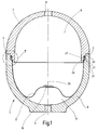
- a in Fig. 1 as a whole with 1 designated pressure accumulator has two Storage housing forming housing shells 3 and 5, which approximately formed hemispherical and connected together at an interface 7 are.
- the Housing shells 3 and 5 at the seam 7 by electron beam welding or laser welding connected to each other gas-tight.
- the housing shells 3 and 5 each have an opening 9 and 11, each for the Attachment of a connection fitting, which is not shown, are provided which the connection to a Gasein- and -nach Stahl also not shown or hydraulic system manufactures.
- the interior of the housing is characterized by a partition in the form of a gas-tight Membrane 13 in a top in Fig. 1 located gas space 15 and a lower, adjacent to the opening 11 liquid space 17 divided.
- the membrane 13 may be formed of an elastomeric material or preferably of a plastic material. It can be about a monolayer membrane made of a polyamide, e.g. PA6, or a polyamide blend, such as polyamide polyolefin, or of polyethylene terephthalate, Polyethylene naphthalate or polyvinylidene chloride.
- the above-mentioned plastics as Be provided barrier layer, at which a cover layer or more Cover layers are or are located.
- the membrane 13 is shown in Fig. 1 in not fully stretched state.
- the smallest volume of the Liquid space 17 corresponds, would a glued to the membrane 13 or molded-on reinforcement 19, acting in the manner of a valve disk, come to rest over the inner edge of the opening 11 and at the opening 11 not only have a sealing effect, but also an impression of the Membrane 13 in the opening 11 by the prevailing in the gas space 15 Prevent pressure.
- the reinforcement 19 can also be made of a material Verdikkung the membrane 13 itself be formed.
- FIG. 1 shows the area designated by II in FIG. 1 on a larger scale, so that the details of the design of the edge region 21 of Membrane 13 and the holding device for the clamping of the membrane 13 are removable.
- the edge region 21 of the membrane 13 has a bead-like thickening 23, which is received between two retaining surfaces, of which the housing shell 5 associated holding surface with 25 and the housing shell. 3 assigned holding surface is denoted by 27.
- the holding surfaces 25 and 27 extend over the entire circumference of the pressure accumulator housing to each other equidistant, so that they have between them an annular gap for recording the edge region 21 of the membrane 13 form, over its axial extent has a constant clear gap width D (Fig. 2).
- Fig. 1 the by the approximately spherical shape of the housing shells 3 and 5 defined longitudinal axis of the pressure accumulator 1 designated 29.
- the defined by this longitudinal axis 29 longitudinal direction of the pressure accumulator is illustrated in Fig. 2 by an auxiliary line 31, to the longitudinal axis 29th is parallel.
- Fig. 2 which is based on the Longitudinal axis 29, outer holding surface 25 under a very sharp Angle ⁇ to the longitudinal direction indicated by the auxiliary line 31, i. inclined relative to the longitudinal axis 29.
- the outer holding surface 25 is therefore part of the lateral surface of a cone whose tip is on the longitudinal axis 29 of the pressure accumulator is located. According to the illustration of FIG.
- FIGS. 1 and 2 are the outer holding surface 25 at the small angle ⁇ , the is preferably about 4 ° to 10 °, with respect to the longitudinal axis 29 inclined so, that the holding surface 25 at its upper end in Fig. 2, i. at its the housing shell 3 facing the end, the largest radial distance from the longitudinal axis 29 has. That of the housing shell 3 facing End of the lower in Fig. 1 and 2 housing shell 5 is therefore edge slightly widened funnel-like. The in the slightly expanded open end the housing shell 5 to be used end portion of FIGS.
- the one housing shell 5 is slightly towards its outer end funnel-like outwardly extended guide surface 34 for the collapse the two housing shells 3.5 provided.
- the other housing shell 3 is for moving together with a housing shell 5 after inside also funnel-shaped narrowing with another guide surface 36 provided, wherein in the contracted state of the two Housing shells 3.5, the two guide surfaces 34,36 in contact with each other are.
- the outer support surface 25 in extension and thus the same inclination to the guide surface 34 associated therewith arranged.
- the inner support surface 27 is in turn parallel to the outer holding surface 25 extending around a step 38 inwardly to the longitudinal axis 29 out offset and the length of each guide surface 34,36 is shorter than the length of each associated holding surface 25.27.
- the one guide surface 34 of the housing shell closes 5 to the free end 32 of the same.
- the holding device in question for the membrane partition can be formed directly from the two housing parts 3.5 or at least partly from a separate mounting ring (not shown), the in one of the two housing shells 3,5, in particular in the lower housing shell 5, can be used.
- the projection 33 is integral with formed in the figure above housing shell 3.
- the housing shell 5 a rigid composite.
- elastic sealing element 41 is provided to one Clamping force for the clamping and the sealing of the edge region 21
- elastic sealing element 41 is provided to produce the membrane 13 .
- This is in the manner of an O-ring between the holding surfaces 25 and 27 clamped and exerts on the end edge 39 of the thickening 23 a in Axial acting clamping force, between a transverse to the support surface 27 extending support surface 43 and the support surface 25 transversely extending support surface 37 acts.
- the sealing element seals 41 both against the support surface 25 and against the support surface 27 out from.
- the sealing element 41 is at the end edge 39 of the thickening 23 of the membrane 13 glued or molded.
Landscapes
- Engineering & Computer Science (AREA)
- Physics & Mathematics (AREA)
- Fluid Mechanics (AREA)
- Mechanical Engineering (AREA)
- General Engineering & Computer Science (AREA)
- Supply Devices, Intensifiers, Converters, And Telemotors (AREA)
- External Artificial Organs (AREA)
- Vehicle Body Suspensions (AREA)
Applications Claiming Priority (3)
| Application Number | Priority Date | Filing Date | Title |
|---|---|---|---|
| DE10116235 | 2001-03-31 | ||
| DE10116235A DE10116235A1 (de) | 2001-03-31 | 2001-03-31 | Hydropneumatischer Druckspeicher |
| EP02722196A EP1373736B1 (fr) | 2001-03-31 | 2002-03-09 | Accumulateur de pression hydropneumatique |
Related Parent Applications (2)
| Application Number | Title | Priority Date | Filing Date |
|---|---|---|---|
| EP02722196.9 Division | 2002-03-09 | ||
| EP02722196A Division EP1373736B1 (fr) | 2001-03-31 | 2002-03-09 | Accumulateur de pression hydropneumatique |
Publications (3)
| Publication Number | Publication Date |
|---|---|
| EP1517048A2 true EP1517048A2 (fr) | 2005-03-23 |
| EP1517048A3 EP1517048A3 (fr) | 2005-11-09 |
| EP1517048B1 EP1517048B1 (fr) | 2007-05-09 |
Family
ID=7680001
Family Applications (2)
| Application Number | Title | Priority Date | Filing Date |
|---|---|---|---|
| EP04030566A Expired - Lifetime EP1517048B1 (fr) | 2001-03-31 | 2002-03-09 | Accumulateur hydropneumatique |
| EP02722196A Expired - Lifetime EP1373736B1 (fr) | 2001-03-31 | 2002-03-09 | Accumulateur de pression hydropneumatique |
Family Applications After (1)
| Application Number | Title | Priority Date | Filing Date |
|---|---|---|---|
| EP02722196A Expired - Lifetime EP1373736B1 (fr) | 2001-03-31 | 2002-03-09 | Accumulateur de pression hydropneumatique |
Country Status (5)
| Country | Link |
|---|---|
| US (1) | US6857450B2 (fr) |
| EP (2) | EP1517048B1 (fr) |
| JP (1) | JP4188697B2 (fr) |
| DE (3) | DE10116235A1 (fr) |
| WO (1) | WO2002079653A1 (fr) |
Cited By (1)
| Publication number | Priority date | Publication date | Assignee | Title |
|---|---|---|---|---|
| WO2023186528A1 (fr) * | 2022-04-02 | 2023-10-05 | Hydac Technology Gmbh | Dispositif de détente |
Families Citing this family (34)
| Publication number | Priority date | Publication date | Assignee | Title |
|---|---|---|---|---|
| US20060254541A1 (en) * | 2005-05-10 | 2006-11-16 | Peter Nushart | Breather for a pump |
| US8359856B2 (en) | 2008-04-09 | 2013-01-29 | Sustainx Inc. | Systems and methods for efficient pumping of high-pressure fluids for energy storage and recovery |
| US8479505B2 (en) | 2008-04-09 | 2013-07-09 | Sustainx, Inc. | Systems and methods for reducing dead volume in compressed-gas energy storage systems |
| US8474255B2 (en) | 2008-04-09 | 2013-07-02 | Sustainx, Inc. | Forming liquid sprays in compressed-gas energy storage systems for effective heat exchange |
| US20100307156A1 (en) | 2009-06-04 | 2010-12-09 | Bollinger Benjamin R | Systems and Methods for Improving Drivetrain Efficiency for Compressed Gas Energy Storage and Recovery Systems |
| US8037678B2 (en) * | 2009-09-11 | 2011-10-18 | Sustainx, Inc. | Energy storage and generation systems and methods using coupled cylinder assemblies |
| US7958731B2 (en) * | 2009-01-20 | 2011-06-14 | Sustainx, Inc. | Systems and methods for combined thermal and compressed gas energy conversion systems |
| US20110266810A1 (en) | 2009-11-03 | 2011-11-03 | Mcbride Troy O | Systems and methods for compressed-gas energy storage using coupled cylinder assemblies |
| US8250863B2 (en) | 2008-04-09 | 2012-08-28 | Sustainx, Inc. | Heat exchange with compressed gas in energy-storage systems |
| US7802426B2 (en) | 2008-06-09 | 2010-09-28 | Sustainx, Inc. | System and method for rapid isothermal gas expansion and compression for energy storage |
| US8240140B2 (en) | 2008-04-09 | 2012-08-14 | Sustainx, Inc. | High-efficiency energy-conversion based on fluid expansion and compression |
| US8448433B2 (en) | 2008-04-09 | 2013-05-28 | Sustainx, Inc. | Systems and methods for energy storage and recovery using gas expansion and compression |
| US8225606B2 (en) | 2008-04-09 | 2012-07-24 | Sustainx, Inc. | Systems and methods for energy storage and recovery using rapid isothermal gas expansion and compression |
| US7832207B2 (en) | 2008-04-09 | 2010-11-16 | Sustainx, Inc. | Systems and methods for energy storage and recovery using compressed gas |
| US8677744B2 (en) | 2008-04-09 | 2014-03-25 | SustaioX, Inc. | Fluid circulation in energy storage and recovery systems |
| WO2010105155A2 (fr) * | 2009-03-12 | 2010-09-16 | Sustainx, Inc. | Systèmes et procédés destinés à améliorer le rendement de transmission pour le stockage d'énergie sous forme de gaz comprimé |
| SI2233844T1 (sl) † | 2009-03-14 | 2014-12-31 | Winkelmann Sp. Z.O.O. | Membranska tlačna ekspanzijska posoda |
| US8104274B2 (en) | 2009-06-04 | 2012-01-31 | Sustainx, Inc. | Increased power in compressed-gas energy storage and recovery |
| US8171728B2 (en) | 2010-04-08 | 2012-05-08 | Sustainx, Inc. | High-efficiency liquid heat exchange in compressed-gas energy storage systems |
| US8191362B2 (en) | 2010-04-08 | 2012-06-05 | Sustainx, Inc. | Systems and methods for reducing dead volume in compressed-gas energy storage systems |
| US8234863B2 (en) | 2010-05-14 | 2012-08-07 | Sustainx, Inc. | Forming liquid sprays in compressed-gas energy storage systems for effective heat exchange |
| US8495872B2 (en) | 2010-08-20 | 2013-07-30 | Sustainx, Inc. | Energy storage and recovery utilizing low-pressure thermal conditioning for heat exchange with high-pressure gas |
| US8578708B2 (en) | 2010-11-30 | 2013-11-12 | Sustainx, Inc. | Fluid-flow control in energy storage and recovery systems |
| WO2012158781A2 (fr) | 2011-05-17 | 2012-11-22 | Sustainx, Inc. | Systèmes et procédés pour un transfert thermique biphasé efficace dans des systèmes de stockage d'énergie à air comprimé |
| US20130091834A1 (en) | 2011-10-14 | 2013-04-18 | Sustainx, Inc. | Dead-volume management in compressed-gas energy storage and recovery systems |
| DE102014000378A1 (de) * | 2014-01-14 | 2015-07-16 | Hydac Technology Gmbh | Hydrospeicher |
| DE102014005511A1 (de) * | 2014-04-12 | 2015-10-15 | Hydac Technology Gmbh | Speichereinrichtungen und Montageverfahren zum Herstellen von solchen Speichereinrichtungen |
| WO2017173122A1 (fr) * | 2016-03-31 | 2017-10-05 | Flexcon Industries, Inc. | Réservoir d'expansion à diaphragme flexible unique découplé |
| IT201600108035A1 (it) * | 2016-10-26 | 2018-04-26 | Hutchinson Srl | Smorzatore per una linea di fluido, in particolare una linea del carburante per un motore a combustione interna |
| US10641431B2 (en) * | 2016-12-22 | 2020-05-05 | Steelhead Composites, Llc | Lightweight composite overwrapped pressure vessels with sectioned liners |
| US11448364B2 (en) | 2016-12-22 | 2022-09-20 | Steelhead Composites, Inc. | Lightweight composite overwrapped accumulators |
| DE102017219496A1 (de) * | 2017-11-02 | 2019-05-02 | Krones Ag | Leimversorgung für Etikettieraggregat mit Leimdrucker |
| US11193506B2 (en) * | 2018-11-15 | 2021-12-07 | Canon Kabushiki Kaisha | Pulsation dampener with gas retention |
| WO2022266373A1 (fr) * | 2021-06-16 | 2022-12-22 | Performance Pulsation Control, Inc. | Bague de compression radiale à diaphragme (drcr tm) permettant d'améliorer la capacité d'étanchéité et la durée de vie des diaphragmes utilisés dans des amortisseurs/des accumulateurs/un équipement de commande de pulsations |
Citations (2)
| Publication number | Priority date | Publication date | Assignee | Title |
|---|---|---|---|---|
| DE2534361A1 (de) | 1975-08-01 | 1977-02-03 | Langen & Co | Hydropneumatischer druckspeicher |
| EP1031729A2 (fr) | 1999-02-23 | 2000-08-30 | Nauchno-Proizvodstvennoe Obiedinenie "Energomash", Imenie Akademika V.P. Glushko | Réservoir pour l'accumulation et l'expulsion d'un liquide |
Family Cites Families (5)
| Publication number | Priority date | Publication date | Assignee | Title |
|---|---|---|---|---|
| GB1023726A (en) * | 1965-02-11 | 1966-03-23 | Viktor Langen | Hydraulic pressure accumulator |
| DE2738683A1 (de) * | 1977-08-27 | 1979-03-08 | Fichtel & Sachs Ag | Membraneinspannung fuer hydropneumatische druckspeicher |
| DE2810882C3 (de) * | 1978-03-13 | 1980-09-18 | Siemens Ag, 1000 Berlin Und 8000 Muenchen | Druckwindkessel für eine druckgeregelte Wasserversorgungsanlage |
| US4321949A (en) * | 1979-03-16 | 1982-03-30 | The Normand Trust | Pressure vessel |
| JPH094601A (ja) * | 1995-06-22 | 1997-01-07 | Nok Corp | アキュムレータ |
-
2001
- 2001-03-31 DE DE10116235A patent/DE10116235A1/de not_active Withdrawn
-
2002
- 2002-03-09 DE DE50204867T patent/DE50204867D1/de not_active Expired - Lifetime
- 2002-03-09 DE DE50210143T patent/DE50210143D1/de not_active Expired - Lifetime
- 2002-03-09 EP EP04030566A patent/EP1517048B1/fr not_active Expired - Lifetime
- 2002-03-09 JP JP2002578034A patent/JP4188697B2/ja not_active Expired - Fee Related
- 2002-03-09 US US10/465,999 patent/US6857450B2/en not_active Expired - Lifetime
- 2002-03-09 WO PCT/EP2002/002626 patent/WO2002079653A1/fr not_active Ceased
- 2002-03-09 EP EP02722196A patent/EP1373736B1/fr not_active Expired - Lifetime
Patent Citations (2)
| Publication number | Priority date | Publication date | Assignee | Title |
|---|---|---|---|---|
| DE2534361A1 (de) | 1975-08-01 | 1977-02-03 | Langen & Co | Hydropneumatischer druckspeicher |
| EP1031729A2 (fr) | 1999-02-23 | 2000-08-30 | Nauchno-Proizvodstvennoe Obiedinenie "Energomash", Imenie Akademika V.P. Glushko | Réservoir pour l'accumulation et l'expulsion d'un liquide |
Cited By (1)
| Publication number | Priority date | Publication date | Assignee | Title |
|---|---|---|---|---|
| WO2023186528A1 (fr) * | 2022-04-02 | 2023-10-05 | Hydac Technology Gmbh | Dispositif de détente |
Also Published As
| Publication number | Publication date |
|---|---|
| US6857450B2 (en) | 2005-02-22 |
| EP1373736B1 (fr) | 2005-11-09 |
| DE10116235A1 (de) | 2002-10-17 |
| EP1373736A1 (fr) | 2004-01-02 |
| JP2004523710A (ja) | 2004-08-05 |
| DE50204867D1 (de) | 2005-12-15 |
| JP4188697B2 (ja) | 2008-11-26 |
| US20040045615A1 (en) | 2004-03-11 |
| EP1517048A3 (fr) | 2005-11-09 |
| WO2002079653A1 (fr) | 2002-10-10 |
| DE50210143D1 (de) | 2007-06-21 |
| EP1517048B1 (fr) | 2007-05-09 |
Similar Documents
| Publication | Publication Date | Title |
|---|---|---|
| EP1517048B1 (fr) | Accumulateur hydropneumatique | |
| EP2223727B1 (fr) | Dispositif de filtre destiné à la filtration de fluides gazeux | |
| EP2430318B1 (fr) | Accumulateur hydraulique | |
| DE102015012357A1 (de) | Hydrospeicher | |
| WO2023078635A1 (fr) | Élément filtrant rond et dispositif filtrant | |
| EP1887263A1 (fr) | Soufflet protecteur | |
| DE102018216989A1 (de) | Druckkörper für ein Druckluftsystem | |
| WO2024061494A1 (fr) | Système de filtre à gaz | |
| DE102009005834A1 (de) | Gassack für ein Fahrzeuginsassen-Rückhaltesystem und Verfahren zum Herstellen eines Gassacks | |
| DE102007037734A1 (de) | Luftströmungskanal aus einem Kunststoffschaum, insbesondere für ein Fahrzeug | |
| DE102011110194A1 (de) | Ansatzstutzen für Filterschläuche | |
| DE29921543U1 (de) | Filtereinsatz für einen Flüssigkeitsfilter | |
| WO2022112185A1 (fr) | Amortisseur de vibrations comprenant des soupapes de commande externes | |
| DE102008034836A1 (de) | Federbein aus einer Luftfeder und einem Stoßdämpfer für Kraftfahrzeuge | |
| WO2025099262A1 (fr) | Filtre à air doté de structures de support qui viennent en prise de manière centrale sur un élément filtrant plat | |
| WO2020070090A1 (fr) | Module de sac gonflable et procédé de montage d'un générateur de gaz dans un sac gonflable | |
| DE202010005994U1 (de) | Membranausdehnungsgefäß | |
| DE102010051756B4 (de) | Filtereinsatz | |
| DE102020114164A1 (de) | Druckspeicher | |
| DE102024002295A1 (de) | Hydrospeicher | |
| DE202015106333U1 (de) | Baugruppe, insbesondere für ein Kraftfahrzeug, mit einem Faltenbalg | |
| DE102015222348A1 (de) | Baugruppe, insbesondere für ein Kraftfahrzeug, mit einem Faltenbalg | |
| EP2982894B1 (fr) | Dispositif de serrage de tuyau | |
| DE102015003756A1 (de) | Filterelement, insbesondere zur Flüssigkeitsfiltration | |
| EP3902620A1 (fr) | Cartouche filtrante pour un filtre à carburant avec filtration à trois étages |
Legal Events
| Date | Code | Title | Description |
|---|---|---|---|
| PUAI | Public reference made under article 153(3) epc to a published international application that has entered the european phase |
Free format text: ORIGINAL CODE: 0009012 |
|
| AC | Divisional application: reference to earlier application |
Ref document number: 1373736 Country of ref document: EP Kind code of ref document: P |
|
| AK | Designated contracting states |
Kind code of ref document: A2 Designated state(s): DE FR GB IT SE |
|
| PUAL | Search report despatched |
Free format text: ORIGINAL CODE: 0009013 |
|
| AK | Designated contracting states |
Kind code of ref document: A3 Designated state(s): DE FR GB IT SE |
|
| 17P | Request for examination filed |
Effective date: 20051108 |
|
| AKX | Designation fees paid |
Designated state(s): DE FR GB IT SE |
|
| GRAP | Despatch of communication of intention to grant a patent |
Free format text: ORIGINAL CODE: EPIDOSNIGR1 |
|
| GRAS | Grant fee paid |
Free format text: ORIGINAL CODE: EPIDOSNIGR3 |
|
| GRAA | (expected) grant |
Free format text: ORIGINAL CODE: 0009210 |
|
| AC | Divisional application: reference to earlier application |
Ref document number: 1373736 Country of ref document: EP Kind code of ref document: P |
|
| AK | Designated contracting states |
Kind code of ref document: B1 Designated state(s): DE FR GB IT SE |
|
| REG | Reference to a national code |
Ref country code: GB Ref legal event code: FG4D Free format text: NOT ENGLISH |
|
| GBT | Gb: translation of ep patent filed (gb section 77(6)(a)/1977) |
Effective date: 20070517 |
|
| REF | Corresponds to: |
Ref document number: 50210143 Country of ref document: DE Date of ref document: 20070621 Kind code of ref document: P |
|
| REG | Reference to a national code |
Ref country code: SE Ref legal event code: TRGR |
|
| ET | Fr: translation filed | ||
| PLBE | No opposition filed within time limit |
Free format text: ORIGINAL CODE: 0009261 |
|
| STAA | Information on the status of an ep patent application or granted ep patent |
Free format text: STATUS: NO OPPOSITION FILED WITHIN TIME LIMIT |
|
| 26N | No opposition filed |
Effective date: 20080212 |
|
| PGFP | Annual fee paid to national office [announced via postgrant information from national office to epo] |
Ref country code: SE Payment date: 20090318 Year of fee payment: 8 |
|
| PGFP | Annual fee paid to national office [announced via postgrant information from national office to epo] |
Ref country code: FR Payment date: 20100305 Year of fee payment: 9 Ref country code: IT Payment date: 20100304 Year of fee payment: 9 |
|
| PGFP | Annual fee paid to national office [announced via postgrant information from national office to epo] |
Ref country code: GB Payment date: 20100212 Year of fee payment: 9 |
|
| EUG | Se: european patent has lapsed | ||
| GBPC | Gb: european patent ceased through non-payment of renewal fee |
Effective date: 20110309 |
|
| REG | Reference to a national code |
Ref country code: FR Ref legal event code: ST Effective date: 20111130 |
|
| PG25 | Lapsed in a contracting state [announced via postgrant information from national office to epo] |
Ref country code: FR Free format text: LAPSE BECAUSE OF NON-PAYMENT OF DUE FEES Effective date: 20110331 |
|
| PG25 | Lapsed in a contracting state [announced via postgrant information from national office to epo] |
Ref country code: GB Free format text: LAPSE BECAUSE OF NON-PAYMENT OF DUE FEES Effective date: 20110309 Ref country code: IT Free format text: LAPSE BECAUSE OF NON-PAYMENT OF DUE FEES Effective date: 20110309 |
|
| PG25 | Lapsed in a contracting state [announced via postgrant information from national office to epo] |
Ref country code: SE Free format text: LAPSE BECAUSE OF NON-PAYMENT OF DUE FEES Effective date: 20100310 |
|
| PGFP | Annual fee paid to national office [announced via postgrant information from national office to epo] |
Ref country code: DE Payment date: 20170222 Year of fee payment: 16 |
|
| REG | Reference to a national code |
Ref country code: DE Ref legal event code: R119 Ref document number: 50210143 Country of ref document: DE |
|
| PG25 | Lapsed in a contracting state [announced via postgrant information from national office to epo] |
Ref country code: DE Free format text: LAPSE BECAUSE OF NON-PAYMENT OF DUE FEES Effective date: 20181002 |