EP1517048B1 - Accumulateur hydropneumatique - Google Patents
Accumulateur hydropneumatique Download PDFInfo
- Publication number
- EP1517048B1 EP1517048B1 EP04030566A EP04030566A EP1517048B1 EP 1517048 B1 EP1517048 B1 EP 1517048B1 EP 04030566 A EP04030566 A EP 04030566A EP 04030566 A EP04030566 A EP 04030566A EP 1517048 B1 EP1517048 B1 EP 1517048B1
- Authority
- EP
- European Patent Office
- Prior art keywords
- housing
- holding
- longitudinal axis
- membrane
- housing shell
- Prior art date
- Legal status (The legal status is an assumption and is not a legal conclusion. Google has not performed a legal analysis and makes no representation as to the accuracy of the status listed.)
- Expired - Lifetime
Links
- 239000012528 membrane Substances 0.000 claims description 42
- 238000007789 sealing Methods 0.000 claims description 20
- 230000008719 thickening Effects 0.000 claims description 13
- 238000003860 storage Methods 0.000 claims description 3
- 239000012530 fluid Substances 0.000 claims 1
- ZZUFCTLCJUWOSV-UHFFFAOYSA-N furosemide Chemical compound C1=C(Cl)C(S(=O)(=O)N)=CC(C(O)=O)=C1NCC1=CC=CO1 ZZUFCTLCJUWOSV-UHFFFAOYSA-N 0.000 claims 1
- 238000005192 partition Methods 0.000 description 7
- 239000004952 Polyamide Substances 0.000 description 3
- 230000008901 benefit Effects 0.000 description 3
- 239000010410 layer Substances 0.000 description 3
- 239000007788 liquid Substances 0.000 description 3
- 239000000463 material Substances 0.000 description 3
- 238000000034 method Methods 0.000 description 3
- 229920002647 polyamide Polymers 0.000 description 3
- 238000000926 separation method Methods 0.000 description 3
- 239000011324 bead Substances 0.000 description 2
- 238000004519 manufacturing process Methods 0.000 description 2
- 239000004033 plastic Substances 0.000 description 2
- 229920003023 plastic Polymers 0.000 description 2
- -1 polyethylene terephthalate Polymers 0.000 description 2
- 230000002787 reinforcement Effects 0.000 description 2
- 238000003466 welding Methods 0.000 description 2
- 229920001328 Polyvinylidene chloride Polymers 0.000 description 1
- 230000001154 acute effect Effects 0.000 description 1
- 230000015572 biosynthetic process Effects 0.000 description 1
- 230000000903 blocking effect Effects 0.000 description 1
- 230000000295 complement effect Effects 0.000 description 1
- 238000006073 displacement reaction Methods 0.000 description 1
- 230000000694 effects Effects 0.000 description 1
- 239000013536 elastomeric material Substances 0.000 description 1
- 238000010894 electron beam technology Methods 0.000 description 1
- 238000004146 energy storage Methods 0.000 description 1
- 238000003780 insertion Methods 0.000 description 1
- 230000037431 insertion Effects 0.000 description 1
- 238000009434 installation Methods 0.000 description 1
- 239000002184 metal Substances 0.000 description 1
- 239000000203 mixture Substances 0.000 description 1
- 230000002093 peripheral effect Effects 0.000 description 1
- 229920003207 poly(ethylene-2,6-naphthalate) Polymers 0.000 description 1
- 239000011112 polyethylene naphthalate Substances 0.000 description 1
- 229920000139 polyethylene terephthalate Polymers 0.000 description 1
- 239000005020 polyethylene terephthalate Substances 0.000 description 1
- 229920000098 polyolefin Polymers 0.000 description 1
- 239000005033 polyvinylidene chloride Substances 0.000 description 1
- 239000002356 single layer Substances 0.000 description 1
Images
Classifications
-
- F—MECHANICAL ENGINEERING; LIGHTING; HEATING; WEAPONS; BLASTING
- F15—FLUID-PRESSURE ACTUATORS; HYDRAULICS OR PNEUMATICS IN GENERAL
- F15B—SYSTEMS ACTING BY MEANS OF FLUIDS IN GENERAL; FLUID-PRESSURE ACTUATORS, e.g. SERVOMOTORS; DETAILS OF FLUID-PRESSURE SYSTEMS, NOT OTHERWISE PROVIDED FOR
- F15B1/00—Installations or systems with accumulators; Supply reservoir or sump assemblies
- F15B1/02—Installations or systems with accumulators
- F15B1/04—Accumulators
- F15B1/08—Accumulators using a gas cushion; Gas charging devices; Indicators or floats therefor
- F15B1/10—Accumulators using a gas cushion; Gas charging devices; Indicators or floats therefor with flexible separating means
- F15B1/12—Accumulators using a gas cushion; Gas charging devices; Indicators or floats therefor with flexible separating means attached at their periphery
- F15B1/125—Accumulators using a gas cushion; Gas charging devices; Indicators or floats therefor with flexible separating means attached at their periphery characterised by the attachment means
-
- F—MECHANICAL ENGINEERING; LIGHTING; HEATING; WEAPONS; BLASTING
- F15—FLUID-PRESSURE ACTUATORS; HYDRAULICS OR PNEUMATICS IN GENERAL
- F15B—SYSTEMS ACTING BY MEANS OF FLUIDS IN GENERAL; FLUID-PRESSURE ACTUATORS, e.g. SERVOMOTORS; DETAILS OF FLUID-PRESSURE SYSTEMS, NOT OTHERWISE PROVIDED FOR
- F15B1/00—Installations or systems with accumulators; Supply reservoir or sump assemblies
- F15B1/02—Installations or systems with accumulators
- F15B1/04—Accumulators
- F15B1/08—Accumulators using a gas cushion; Gas charging devices; Indicators or floats therefor
- F15B1/10—Accumulators using a gas cushion; Gas charging devices; Indicators or floats therefor with flexible separating means
- F15B1/106—Accumulators using a gas cushion; Gas charging devices; Indicators or floats therefor with flexible separating means characterised by the way housing components are assembled
-
- F—MECHANICAL ENGINEERING; LIGHTING; HEATING; WEAPONS; BLASTING
- F15—FLUID-PRESSURE ACTUATORS; HYDRAULICS OR PNEUMATICS IN GENERAL
- F15B—SYSTEMS ACTING BY MEANS OF FLUIDS IN GENERAL; FLUID-PRESSURE ACTUATORS, e.g. SERVOMOTORS; DETAILS OF FLUID-PRESSURE SYSTEMS, NOT OTHERWISE PROVIDED FOR
- F15B1/00—Installations or systems with accumulators; Supply reservoir or sump assemblies
- F15B1/02—Installations or systems with accumulators
- F15B1/04—Accumulators
- F15B1/08—Accumulators using a gas cushion; Gas charging devices; Indicators or floats therefor
- F15B1/10—Accumulators using a gas cushion; Gas charging devices; Indicators or floats therefor with flexible separating means
- F15B1/12—Accumulators using a gas cushion; Gas charging devices; Indicators or floats therefor with flexible separating means attached at their periphery
-
- F—MECHANICAL ENGINEERING; LIGHTING; HEATING; WEAPONS; BLASTING
- F15—FLUID-PRESSURE ACTUATORS; HYDRAULICS OR PNEUMATICS IN GENERAL
- F15B—SYSTEMS ACTING BY MEANS OF FLUIDS IN GENERAL; FLUID-PRESSURE ACTUATORS, e.g. SERVOMOTORS; DETAILS OF FLUID-PRESSURE SYSTEMS, NOT OTHERWISE PROVIDED FOR
- F15B2201/00—Accumulators
- F15B2201/20—Accumulator cushioning means
- F15B2201/205—Accumulator cushioning means using gas
-
- F—MECHANICAL ENGINEERING; LIGHTING; HEATING; WEAPONS; BLASTING
- F15—FLUID-PRESSURE ACTUATORS; HYDRAULICS OR PNEUMATICS IN GENERAL
- F15B—SYSTEMS ACTING BY MEANS OF FLUIDS IN GENERAL; FLUID-PRESSURE ACTUATORS, e.g. SERVOMOTORS; DETAILS OF FLUID-PRESSURE SYSTEMS, NOT OTHERWISE PROVIDED FOR
- F15B2201/00—Accumulators
- F15B2201/30—Accumulator separating means
- F15B2201/315—Accumulator separating means having flexible separating means
- F15B2201/3151—Accumulator separating means having flexible separating means the flexible separating means being diaphragms or membranes
-
- F—MECHANICAL ENGINEERING; LIGHTING; HEATING; WEAPONS; BLASTING
- F15—FLUID-PRESSURE ACTUATORS; HYDRAULICS OR PNEUMATICS IN GENERAL
- F15B—SYSTEMS ACTING BY MEANS OF FLUIDS IN GENERAL; FLUID-PRESSURE ACTUATORS, e.g. SERVOMOTORS; DETAILS OF FLUID-PRESSURE SYSTEMS, NOT OTHERWISE PROVIDED FOR
- F15B2201/00—Accumulators
- F15B2201/30—Accumulator separating means
- F15B2201/315—Accumulator separating means having flexible separating means
- F15B2201/3156—Accumulator separating means having flexible separating means characterised by their attachment
-
- F—MECHANICAL ENGINEERING; LIGHTING; HEATING; WEAPONS; BLASTING
- F15—FLUID-PRESSURE ACTUATORS; HYDRAULICS OR PNEUMATICS IN GENERAL
- F15B—SYSTEMS ACTING BY MEANS OF FLUIDS IN GENERAL; FLUID-PRESSURE ACTUATORS, e.g. SERVOMOTORS; DETAILS OF FLUID-PRESSURE SYSTEMS, NOT OTHERWISE PROVIDED FOR
- F15B2201/00—Accumulators
- F15B2201/40—Constructional details of accumulators not otherwise provided for
- F15B2201/41—Liquid ports
- F15B2201/411—Liquid ports having valve means
-
- F—MECHANICAL ENGINEERING; LIGHTING; HEATING; WEAPONS; BLASTING
- F15—FLUID-PRESSURE ACTUATORS; HYDRAULICS OR PNEUMATICS IN GENERAL
- F15B—SYSTEMS ACTING BY MEANS OF FLUIDS IN GENERAL; FLUID-PRESSURE ACTUATORS, e.g. SERVOMOTORS; DETAILS OF FLUID-PRESSURE SYSTEMS, NOT OTHERWISE PROVIDED FOR
- F15B2201/00—Accumulators
- F15B2201/40—Constructional details of accumulators not otherwise provided for
- F15B2201/415—Gas ports
-
- F—MECHANICAL ENGINEERING; LIGHTING; HEATING; WEAPONS; BLASTING
- F15—FLUID-PRESSURE ACTUATORS; HYDRAULICS OR PNEUMATICS IN GENERAL
- F15B—SYSTEMS ACTING BY MEANS OF FLUIDS IN GENERAL; FLUID-PRESSURE ACTUATORS, e.g. SERVOMOTORS; DETAILS OF FLUID-PRESSURE SYSTEMS, NOT OTHERWISE PROVIDED FOR
- F15B2201/00—Accumulators
- F15B2201/40—Constructional details of accumulators not otherwise provided for
- F15B2201/43—Anti-extrusion means
- F15B2201/435—Anti-extrusion means being fixed to the separating means
Definitions
- the invention relates to a hydropneumatic pressure accumulator with a housing formed from at least two interconnected housing shells, which separates the interior of the memory from the outside environment, with a longitudinal axis defining a cross-section and the interior of the housing in two spaces, in particular a gas space and a liquid space , dividing partition in the form of a gas-tight membrane, which is clamped with its peripheral edge region to form a seal to the inner wall of the housing by means of a holding device which has the edge region of the membrane between receiving retaining surfaces and at least one force generating element generating a clamping force between edge region and retaining surfaces, wherein at least one of the retaining surfaces is formed by a wall portion of one of the housing shells, wherein the retaining surfaces extend over their entire surface area to each other equidistant between them a Ringspa lt being formed, which has a constant clear gap width over its axial extent, and wherein the holding surface located on one of the housing shells, with respect to the longitudinal axi
- Comparable accumulators are known for example from DE 25 34 361 B2. Due to the very tight tolerances, as they are to be observed in the cooperating wall parts at the connecting portion of the housing shells and for the edge region of the membrane contacting surfaces, the installation of the membrane and the assembly of the housing shells designed relatively difficult. Because of the exact fit smallest misalignment or tilt error relative to the longitudinal axis when moving the parts to disturbances of the assembly process or even damage due to misalignment or tilting.
- a generic hydropneumatic pressure accumulator wherein a separate attachment ring is provided as a holding device for the partition or separation membrane, which clamped between two housing shells makes the determination.
- the mounting ring as a holding device presses over a flange-like metal ring an end-side membrane bead in the associated receptacle of the lower housing shell of the memory.
- the housing shells are cylindrical at their mutually facing guide surfaces and thus in abutment with each other.
- the mounting ring and the lower housing shell extend over a predeterminable area below the Festlegewulstes with mutually parallel retaining surfaces which define an equidistant gap with each other and hold the partition over such a predetermined distance. If the housing shells are brought together during assembly of the known memory, even if the guide and retaining surfaces are precisely machined, a misalignment can occur, which impairs the clamping of the diaphragm and its subsequent fixing in the memory and can make the assembly considerably more difficult.
- the invention has the object to provide a pressure accumulator of the type mentioned, which is characterized by a particularly simple assembly-enabling design and does not have the disadvantages described in the prior art.
- This object is achieved by a hydropneumatic accumulator with the features of claim 1 in its entirety.
- the other housing shell for the collapse with the one housing shell on the inside a funnel-shaped narrowing further guide surface, wherein in the contracted state of the two housing shells, the two guide surfaces in abutment with each other and / or maintain an equidistant distance from one another.
- the outer holding surface extends in extension and thus the same inclination to its associated guide surface.
- the inner support surface is parallel to the outer support surface extending arranged offset by one step inwardly to the longitudinal axis of the memory. Due to the pertinent arrangement, the holding surfaces can be formed in meaningful continuation of the guide surfaces, which significantly reduces the production costs.
- the holding device can be formed directly from the two housing shells and an additional mounting ring can be completely dispensed with. While retaining the advantages of the invention, it is also possible to implement the pertinent arrangement in another embodiment by using a fastening ring, which, however, then increases the number of parts and, consequently, the production costs.
- each guide surface is dimensioned shorter than the length of each associated holding surface.
- the preferred range for the angle at which the outer holding surface widens outwardly in a funnel-like manner with respect to the longitudinal axis is 4 ° to 10 °, preferably 5 ° to 6 °.
- The, relative to the longitudinal axis, inner support surface may be formed, for example, on a plug-in in a housing shell approach the other housing shell. If, in this case, the projection is formed integrally with the other housing shell, then at least one elastic sealing element arranged between at least one holding surface and the edge region of the membrane can be provided as the clamping force between the edge region of the membrane and retaining surfaces.
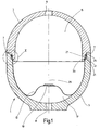
- a pressure accumulator designated as a whole by 1 in FIG. 1 has two housing shells 3 and 5 which form the storage housing and which are approximately hemispherical in shape and connected to one another at an interface 7.
- the housing shells 3 and 5 are gas-tightly connected to each other at the seam 7 by electron beam welding or laser welding.
- the housing shells 3 and 5 each have an opening 9 or 11, each of which is provided for the attachment of a connection fitting, which is not shown, which connects to a Gasein- andnach Stahl also not shown or hydraulic system manufactures.
- the interior of the housing is divided by a partition wall in the form of a gas-tight membrane 13 in a gas space 15 located at the top in FIG. 1 and a lower liquid space 17 adjoining the opening 11.
- the membrane 13 may be formed of an elastomeric material or preferably of a plastic material. It may be a monolayer membrane which consists of a polyamide, for example PA6, or a polyamide blend, such as polyamide polyolefin, or of polyethylene terephthalate, polyethylene naphthalate or polyvinylidene chloride.
- the above-mentioned plastics as Be provided blocking layer on which a cover layer or multiple cover layers is or are located.
- the membrane 13 is shown in Fig. 1 in not fully stretched state.
- a glued to the membrane 13 or molded reinforcement 19 acting in the manner of a valve disk would come to lie over the inner edge of the opening 11 and not at the opening 11 only act sealing, but also prevent depression of the membrane 13 in the opening 11 by the pressure prevailing in the gas space 15 pressure.
- the reinforcement 19 may also be formed from a material thickening of the membrane 13 itself.
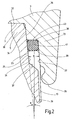
- Fig. 2 shows the designated in Fig. 1 with II area on a larger scale, so that the details of the design of the edge portion 21 of the membrane 13 and the holding means for the clamping of the diaphragm 13 can be removed.
- the edge region 21 of the membrane 13 has a bead-like thickening 23 which is received between two retaining surfaces, of which the housing shell 5 associated holding surface with 25 and the housing shell 3 associated holding surface 27 is designated ,
- the holding surfaces 25 and 27 extend over the entire circumference of the pressure accumulator housing to each other equidistant, so that they form between them an annular gap for receiving the edge region 21 of the membrane 13, which has a constant clearance width D over its axial extent (Fig.
- Fig. 1 the axis defined by the approximately spherical shape of the housing shells 3 and 5 longitudinal axis of the pressure accumulator 1 is denoted by 29.
- the defined by this longitudinal axis 29 longitudinal direction of the pressure accumulator is illustrated in Fig. 2 by an auxiliary line 31 which is parallel to the longitudinal axis 29.
- the holding surface 25 lying outside on the longitudinal axis 29 is inclined at a very acute angle ⁇ to the longitudinal direction indicated by the auxiliary line 31, ie, relative to the longitudinal axis 29.
- the outer holding surface 25 is therefore part of the lateral surface of a cone whose tip is located on the longitudinal axis 29 of the pressure accumulator.
- the outer holding surface 25 at the small angle ⁇ which is preferably about 4 ° to 10 °, relative to the longitudinal axis 29 inclined so that the support surface 25 at its upper end in Fig. 2, that is, at its the housing shell 3 facing the end, the largest radial distance from the longitudinal axis 29 has.
- the housing shell 3 facing the end of the housing shell 5 located in Fig. 1 and 2 below is therefore slightly widened at the edge funnel-like. The inserted into the slightly extended open end of the housing shell 5 end portion of the top in Figs.
- the one housing shell 5 is provided to its outer end with a slightly funnel-like outwardly extended guide surface 34 for the collapse of the two housing shells 3.5.
- the other housing shell 3 is also funnel-shaped narrowing provided with a further guide surface 36 for moving together with a housing shell 5 inside, wherein in the contracted state of the two housing shells 3.5, the two guide surfaces 34,36 in abutment with each other.
- the outer holding surface 25 in extension and thus the same inclination to the associated guide surface 34 is arranged to extend.
- the inner support surface 27 is in turn arranged offset parallel to the outer support surface 25 by a step 38 inwardly to the longitudinal axis 29 out and the length of each guide surface 34,36 is shorter than the length of each associated support surface 25,27.
- the one guide surface 34 of the housing shell 5 connects to the free end 32 thereof.
- the holding device in question for the membrane partition wall can be formed directly from the two housing parts 3,5 or at least partially from an independent mounting ring (not shown), which is in one of the two housing shells 3,5, in particular in the lower housing shell 5, can be used ,
- the projection 33 is formed integrally with the housing shell 3 located at the top in the figure.
- the projection 33 forms a rigid connection with the housing shell 5.
- elastic sealing element 41 is provided in order to generate a clamping force for the clamping and the sealing of the edge region 21 of the membrane 13, as an energy storage element at the end edge 39 of the thickening 23 fitting.
- elastic sealing element 41 is provided in order to generate a clamping force for the clamping and the sealing of the edge region 21 of the membrane 13, as an energy storage element at the end edge 39 of the thickening 23 fitting.
- elastic sealing element 41 is provided in the manner of an O-ring between the holding surfaces 25 and 27 and exerts on the end edge 39 of the thickening 23 an axially acting clamping force between a transverse to the support surface 27 extending support surface 43 and the support surface 25 transversely extending support surface 37 acts.
- the sealing member 41 seals both against the support surface 25 and against the support surface 27 from.
- the sealing element 41 is glued or molded on the end edge 39 of the thick
Landscapes
- Engineering & Computer Science (AREA)
- Physics & Mathematics (AREA)
- Fluid Mechanics (AREA)
- Mechanical Engineering (AREA)
- General Engineering & Computer Science (AREA)
- Supply Devices, Intensifiers, Converters, And Telemotors (AREA)
- External Artificial Organs (AREA)
- Vehicle Body Suspensions (AREA)
Claims (8)
- Accumulateur hydropneumatique (1) comportant un boîtier qui est formé d'au moins deux coques de boîtier (3, 5) susceptibles d'être reliées l'une à l'autre et qui sépare de l'environnement extérieur l'intérieur de l'accumulateur, comportant une section transversale qui définit un axe longitudinal (29) ainsi qu'une paroi séparatrice qui divise l'espace intérieur du boîtier en deux chambres, en particulier une chambre à gaz (15) et une chambre à liquide (17), sous forme d'une membrane (13) étanche au gaz dont la zone de bord (21) périphérique est tendue en formant un joint par rapport à la paroi intérieure du boîtier à l'aide d'un dispositif de retenue muni de surfaces de retenue (25, 27) qui reçoivent entre elles la zone de bord (21) de la membrane (13) et d'au moins un élément accumulateur de force (41) qui produit une force de serrage entre la zone de bord (21) et les surfaces de retenue (25, 27), dans cet accumulateur au moins une (25) des surfaces de retenue (25, 27) est formée par une partie de paroi d'une des coques de boîtier (3, 5), les surfaces de retenue (25, 27) sont équidistantes l'une de l'autre sur toute la zone de leur surface pour former entre elles un interstice annulaire dont la largeur intérieure (D) d'interstice est constante sur toute son étendue axiale, et la surface de retenue (25), celle à l'extérieur si on se réfère à l'axe longitudinal (29), qui se trouve sur l'une des (5) coques de boîtier (3, 5) fait partie de la surface latérale d'un cône dont le sommet est placé sur l'axe longitudinal (29) de telle manière que, à son extrémité orientée vers l'autre coque de boîtier (3), cette surface de retenue (25) a l'écart radial maximal par rapport à l'axe longitudinal (29),
caractérisé en ce que, entre son extrémité libre (32) et l'élément d'étanchéité (41) respectif, au moins la zone d'extrémité (30) de l'une des coques de boîtier (5) a une surface de guidage (34) en entonnoir qui s'élargit vers l'extérieur et qui sert à assembler les deux coques de boîtier (3, 5),
qu'au moins un élément d'étanchéité (41) élastique est prévu sur au moins une surface de retenue (25, 27) pour produire une force de serrage qui agit sur la zone de bord (21) de la membrane (13),
que la zone de bord (21) de la membrane (13) comporte un épaississement (23) en bourrelet reçu entre les surfaces de retenue (25, 27)
et que l'élément d'étanchéité prévu est une bague d'étanchéité (41) élastique qui est en contact avec le bord d'extrémité (39) de l'épaississement (23) ou y est injectée et qui produit une force de serrage entre l'épaississement (23) en bourrelet et des surfaces d'appui (37, 43) formées sur l'une et l'autre des coques de boîtier (5 ou 3) et transversales aux surfaces de retenue (25, 27). - Accumulateur selon la revendication 1, caractérisé en ce que pour assembler la coque de boîtier (5) l'autre coque de boîtier (3) comporte une autre surface de guidage (36) en entonnoir qui se rétrécit vers l'intérieur et que, quand les deux coques de boîtier (3, 5) sont à l'état assemblé, les deux surfaces de guidage (34, 36) sont en contact l'une avec l'autre et/ou sont équidistantes l'une de l'autre.
- Accumulateur selon la revendication 1 ou 2, caractérisé en ce que la surface de retenue (25) extérieure prolonge la surface de guidage (34) qui lui est associée et a donc la même inclinaison qu'elle.
- Accumulateur selon la revendication 3, caractérisé en ce que la surface de retenue (27) intérieure qui est parallèle à la surface de retenue (25) extérieure est décalée d'un palier (38) vers l'intérieur par rapport à l'axe longitudinal (29) de l'accumulateur (1).
- Accumulateur selon l'une des revendications 1 à 4, caractérisé en ce que le dispositif de retenue est directement formé à partir des deux coques de boîtier (3, 5) ou au moins en partie à partir d'une bague de fixation qui peut être introduite dans une des deux coques de boîtier (3, 5).
- Accumulateur selon la revendication 4 ou 5, caractérisé en ce que la longueur de chacune des surfaces de guidage (34, 36) est moindre que la longueur de chacune des surfaces de retenue (25, 27) associées.
- Accumulateur selon l'une des revendications 1 à 6, caractérisé en ce que l'angle (α) du cône qui définit la surface de retenue (25) formée sur l'une des coques de boîtier (5) fait de 4° à 10° par rapport à l'axe longitudinal (29).
- Accumulateur selon l'une des revendications 1 à 7, caractérisé en ce que la surface de retenue (27), celle à l'intérieur si on se réfère à l'axe longitudinal (29), est formée sur un épaulement (33, 45) - qui peut être enfoncé dans l'une des coques de boîtier (5) - de l'autre coque de boîtier (3).
Applications Claiming Priority (3)
| Application Number | Priority Date | Filing Date | Title |
|---|---|---|---|
| DE10116235 | 2001-03-31 | ||
| DE10116235A DE10116235A1 (de) | 2001-03-31 | 2001-03-31 | Hydropneumatischer Druckspeicher |
| EP02722196A EP1373736B1 (fr) | 2001-03-31 | 2002-03-09 | Accumulateur de pression hydropneumatique |
Related Parent Applications (2)
| Application Number | Title | Priority Date | Filing Date |
|---|---|---|---|
| EP02722196.9 Division | 2002-03-09 | ||
| EP02722196A Division EP1373736B1 (fr) | 2001-03-31 | 2002-03-09 | Accumulateur de pression hydropneumatique |
Publications (3)
| Publication Number | Publication Date |
|---|---|
| EP1517048A2 EP1517048A2 (fr) | 2005-03-23 |
| EP1517048A3 EP1517048A3 (fr) | 2005-11-09 |
| EP1517048B1 true EP1517048B1 (fr) | 2007-05-09 |
Family
ID=7680001
Family Applications (2)
| Application Number | Title | Priority Date | Filing Date |
|---|---|---|---|
| EP04030566A Expired - Lifetime EP1517048B1 (fr) | 2001-03-31 | 2002-03-09 | Accumulateur hydropneumatique |
| EP02722196A Expired - Lifetime EP1373736B1 (fr) | 2001-03-31 | 2002-03-09 | Accumulateur de pression hydropneumatique |
Family Applications After (1)
| Application Number | Title | Priority Date | Filing Date |
|---|---|---|---|
| EP02722196A Expired - Lifetime EP1373736B1 (fr) | 2001-03-31 | 2002-03-09 | Accumulateur de pression hydropneumatique |
Country Status (5)
| Country | Link |
|---|---|
| US (1) | US6857450B2 (fr) |
| EP (2) | EP1517048B1 (fr) |
| JP (1) | JP4188697B2 (fr) |
| DE (3) | DE10116235A1 (fr) |
| WO (1) | WO2002079653A1 (fr) |
Families Citing this family (35)
| Publication number | Priority date | Publication date | Assignee | Title |
|---|---|---|---|---|
| US20060254541A1 (en) * | 2005-05-10 | 2006-11-16 | Peter Nushart | Breather for a pump |
| US8359856B2 (en) | 2008-04-09 | 2013-01-29 | Sustainx Inc. | Systems and methods for efficient pumping of high-pressure fluids for energy storage and recovery |
| US8479505B2 (en) | 2008-04-09 | 2013-07-09 | Sustainx, Inc. | Systems and methods for reducing dead volume in compressed-gas energy storage systems |
| US8474255B2 (en) | 2008-04-09 | 2013-07-02 | Sustainx, Inc. | Forming liquid sprays in compressed-gas energy storage systems for effective heat exchange |
| US20100307156A1 (en) | 2009-06-04 | 2010-12-09 | Bollinger Benjamin R | Systems and Methods for Improving Drivetrain Efficiency for Compressed Gas Energy Storage and Recovery Systems |
| US8037678B2 (en) * | 2009-09-11 | 2011-10-18 | Sustainx, Inc. | Energy storage and generation systems and methods using coupled cylinder assemblies |
| US7958731B2 (en) * | 2009-01-20 | 2011-06-14 | Sustainx, Inc. | Systems and methods for combined thermal and compressed gas energy conversion systems |
| US20110266810A1 (en) | 2009-11-03 | 2011-11-03 | Mcbride Troy O | Systems and methods for compressed-gas energy storage using coupled cylinder assemblies |
| US8250863B2 (en) | 2008-04-09 | 2012-08-28 | Sustainx, Inc. | Heat exchange with compressed gas in energy-storage systems |
| US7802426B2 (en) | 2008-06-09 | 2010-09-28 | Sustainx, Inc. | System and method for rapid isothermal gas expansion and compression for energy storage |
| US8240140B2 (en) | 2008-04-09 | 2012-08-14 | Sustainx, Inc. | High-efficiency energy-conversion based on fluid expansion and compression |
| US8448433B2 (en) | 2008-04-09 | 2013-05-28 | Sustainx, Inc. | Systems and methods for energy storage and recovery using gas expansion and compression |
| US8225606B2 (en) | 2008-04-09 | 2012-07-24 | Sustainx, Inc. | Systems and methods for energy storage and recovery using rapid isothermal gas expansion and compression |
| US7832207B2 (en) | 2008-04-09 | 2010-11-16 | Sustainx, Inc. | Systems and methods for energy storage and recovery using compressed gas |
| US8677744B2 (en) | 2008-04-09 | 2014-03-25 | SustaioX, Inc. | Fluid circulation in energy storage and recovery systems |
| WO2010105155A2 (fr) * | 2009-03-12 | 2010-09-16 | Sustainx, Inc. | Systèmes et procédés destinés à améliorer le rendement de transmission pour le stockage d'énergie sous forme de gaz comprimé |
| SI2233844T1 (sl) † | 2009-03-14 | 2014-12-31 | Winkelmann Sp. Z.O.O. | Membranska tlačna ekspanzijska posoda |
| US8104274B2 (en) | 2009-06-04 | 2012-01-31 | Sustainx, Inc. | Increased power in compressed-gas energy storage and recovery |
| US8171728B2 (en) | 2010-04-08 | 2012-05-08 | Sustainx, Inc. | High-efficiency liquid heat exchange in compressed-gas energy storage systems |
| US8191362B2 (en) | 2010-04-08 | 2012-06-05 | Sustainx, Inc. | Systems and methods for reducing dead volume in compressed-gas energy storage systems |
| US8234863B2 (en) | 2010-05-14 | 2012-08-07 | Sustainx, Inc. | Forming liquid sprays in compressed-gas energy storage systems for effective heat exchange |
| US8495872B2 (en) | 2010-08-20 | 2013-07-30 | Sustainx, Inc. | Energy storage and recovery utilizing low-pressure thermal conditioning for heat exchange with high-pressure gas |
| US8578708B2 (en) | 2010-11-30 | 2013-11-12 | Sustainx, Inc. | Fluid-flow control in energy storage and recovery systems |
| WO2012158781A2 (fr) | 2011-05-17 | 2012-11-22 | Sustainx, Inc. | Systèmes et procédés pour un transfert thermique biphasé efficace dans des systèmes de stockage d'énergie à air comprimé |
| US20130091834A1 (en) | 2011-10-14 | 2013-04-18 | Sustainx, Inc. | Dead-volume management in compressed-gas energy storage and recovery systems |
| DE102014000378A1 (de) * | 2014-01-14 | 2015-07-16 | Hydac Technology Gmbh | Hydrospeicher |
| DE102014005511A1 (de) * | 2014-04-12 | 2015-10-15 | Hydac Technology Gmbh | Speichereinrichtungen und Montageverfahren zum Herstellen von solchen Speichereinrichtungen |
| WO2017173122A1 (fr) * | 2016-03-31 | 2017-10-05 | Flexcon Industries, Inc. | Réservoir d'expansion à diaphragme flexible unique découplé |
| IT201600108035A1 (it) * | 2016-10-26 | 2018-04-26 | Hutchinson Srl | Smorzatore per una linea di fluido, in particolare una linea del carburante per un motore a combustione interna |
| US10641431B2 (en) * | 2016-12-22 | 2020-05-05 | Steelhead Composites, Llc | Lightweight composite overwrapped pressure vessels with sectioned liners |
| US11448364B2 (en) | 2016-12-22 | 2022-09-20 | Steelhead Composites, Inc. | Lightweight composite overwrapped accumulators |
| DE102017219496A1 (de) * | 2017-11-02 | 2019-05-02 | Krones Ag | Leimversorgung für Etikettieraggregat mit Leimdrucker |
| US11193506B2 (en) * | 2018-11-15 | 2021-12-07 | Canon Kabushiki Kaisha | Pulsation dampener with gas retention |
| WO2022266373A1 (fr) * | 2021-06-16 | 2022-12-22 | Performance Pulsation Control, Inc. | Bague de compression radiale à diaphragme (drcr tm) permettant d'améliorer la capacité d'étanchéité et la durée de vie des diaphragmes utilisés dans des amortisseurs/des accumulateurs/un équipement de commande de pulsations |
| DE102022001144A1 (de) * | 2022-04-02 | 2023-10-05 | Hydac Technology Gmbh | Ausdehnungsvorrichtung |
Family Cites Families (7)
| Publication number | Priority date | Publication date | Assignee | Title |
|---|---|---|---|---|
| GB1023726A (en) * | 1965-02-11 | 1966-03-23 | Viktor Langen | Hydraulic pressure accumulator |
| DE2534361B2 (de) * | 1975-08-01 | 1977-05-18 | Langen & Co, 4000 Düsseldorf | Hydropneumatischer druckspeicher |
| DE2738683A1 (de) * | 1977-08-27 | 1979-03-08 | Fichtel & Sachs Ag | Membraneinspannung fuer hydropneumatische druckspeicher |
| DE2810882C3 (de) * | 1978-03-13 | 1980-09-18 | Siemens Ag, 1000 Berlin Und 8000 Muenchen | Druckwindkessel für eine druckgeregelte Wasserversorgungsanlage |
| US4321949A (en) * | 1979-03-16 | 1982-03-30 | The Normand Trust | Pressure vessel |
| JPH094601A (ja) * | 1995-06-22 | 1997-01-07 | Nok Corp | アキュムレータ |
| RU2158699C1 (ru) * | 1999-02-23 | 2000-11-10 | Открытое акционерное общество НПО Энергомаш имени академика В.П. Глушко | Бак для хранения и вытеснения жидкости |
-
2001
- 2001-03-31 DE DE10116235A patent/DE10116235A1/de not_active Withdrawn
-
2002
- 2002-03-09 DE DE50204867T patent/DE50204867D1/de not_active Expired - Lifetime
- 2002-03-09 DE DE50210143T patent/DE50210143D1/de not_active Expired - Lifetime
- 2002-03-09 EP EP04030566A patent/EP1517048B1/fr not_active Expired - Lifetime
- 2002-03-09 JP JP2002578034A patent/JP4188697B2/ja not_active Expired - Fee Related
- 2002-03-09 US US10/465,999 patent/US6857450B2/en not_active Expired - Lifetime
- 2002-03-09 WO PCT/EP2002/002626 patent/WO2002079653A1/fr not_active Ceased
- 2002-03-09 EP EP02722196A patent/EP1373736B1/fr not_active Expired - Lifetime
Non-Patent Citations (1)
| Title |
|---|
| None * |
Also Published As
| Publication number | Publication date |
|---|---|
| US6857450B2 (en) | 2005-02-22 |
| EP1373736B1 (fr) | 2005-11-09 |
| DE10116235A1 (de) | 2002-10-17 |
| EP1373736A1 (fr) | 2004-01-02 |
| JP2004523710A (ja) | 2004-08-05 |
| DE50204867D1 (de) | 2005-12-15 |
| JP4188697B2 (ja) | 2008-11-26 |
| EP1517048A2 (fr) | 2005-03-23 |
| US20040045615A1 (en) | 2004-03-11 |
| EP1517048A3 (fr) | 2005-11-09 |
| WO2002079653A1 (fr) | 2002-10-10 |
| DE50210143D1 (de) | 2007-06-21 |
Similar Documents
| Publication | Publication Date | Title |
|---|---|---|
| EP1517048B1 (fr) | Accumulateur hydropneumatique | |
| DE4026934C2 (fr) | ||
| DE60119792T2 (de) | Druckspeicher | |
| EP2810855B1 (fr) | Bouchon étanche | |
| EP2757299B1 (fr) | Dispositif de serrage de tuyau | |
| EP2430318B1 (fr) | Accumulateur hydraulique | |
| DE102016001132A1 (de) | Filterelement, Elementrahmen eines Filterelements, Filterbalg eines Filterelements, Filtergehäuse und Filter | |
| EP0946245B1 (fr) | Tuyau central encliquete | |
| DE102018118397A1 (de) | Verbindungsstruktur für Druckbehälter, Tankmodul mit derselben und Herstellungsverfahren des Tankmoduls | |
| DE102015012357A1 (de) | Hydrospeicher | |
| WO2021013648A1 (fr) | Dispositif de filtration | |
| DE3800656A1 (de) | Hydraulisch daempfende huelsengummifeder | |
| EP2487399A1 (fr) | Raccord emboîtable pour conduites de fluide | |
| EP3953624B1 (fr) | Soupape antidéflagrante pour le désaccouplement de parties d'installations ou de pièces, dotée d'une bague d'étanchéité | |
| DE102008005717A1 (de) | Kraftstofftank mit einem Einfüllrohr und einem Einfüllstutzenkopf | |
| EP0604445B1 (fr) | Accumulateur a membrane avec bague de fixation | |
| EP2930374A1 (fr) | Dispositifs de stockage et procédé de montage destiné à fabriquer de tels dispositifs de stockage | |
| DE102008062837A1 (de) | Hydrospeicher | |
| DE102007037734A1 (de) | Luftströmungskanal aus einem Kunststoffschaum, insbesondere für ein Fahrzeug | |
| WO2025099262A1 (fr) | Filtre à air doté de structures de support qui viennent en prise de manière centrale sur un élément filtrant plat | |
| EP4034279A1 (fr) | Agencement de joint d'étanchéité pour un filtre, en particulier un filtre à air comprimé, et élément filtrant pour un filtre | |
| DE102005058161B4 (de) | Schnellverschluss für den Installationsbereich | |
| EP1136337A1 (fr) | Cylindre combiné de frein de service et à ressort | |
| DE102019005325A1 (de) | Filtervorrichtung | |
| DE202010005994U1 (de) | Membranausdehnungsgefäß |
Legal Events
| Date | Code | Title | Description |
|---|---|---|---|
| PUAI | Public reference made under article 153(3) epc to a published international application that has entered the european phase |
Free format text: ORIGINAL CODE: 0009012 |
|
| AC | Divisional application: reference to earlier application |
Ref document number: 1373736 Country of ref document: EP Kind code of ref document: P |
|
| AK | Designated contracting states |
Kind code of ref document: A2 Designated state(s): DE FR GB IT SE |
|
| PUAL | Search report despatched |
Free format text: ORIGINAL CODE: 0009013 |
|
| AK | Designated contracting states |
Kind code of ref document: A3 Designated state(s): DE FR GB IT SE |
|
| 17P | Request for examination filed |
Effective date: 20051108 |
|
| AKX | Designation fees paid |
Designated state(s): DE FR GB IT SE |
|
| GRAP | Despatch of communication of intention to grant a patent |
Free format text: ORIGINAL CODE: EPIDOSNIGR1 |
|
| GRAS | Grant fee paid |
Free format text: ORIGINAL CODE: EPIDOSNIGR3 |
|
| GRAA | (expected) grant |
Free format text: ORIGINAL CODE: 0009210 |
|
| AC | Divisional application: reference to earlier application |
Ref document number: 1373736 Country of ref document: EP Kind code of ref document: P |
|
| AK | Designated contracting states |
Kind code of ref document: B1 Designated state(s): DE FR GB IT SE |
|
| REG | Reference to a national code |
Ref country code: GB Ref legal event code: FG4D Free format text: NOT ENGLISH |
|
| GBT | Gb: translation of ep patent filed (gb section 77(6)(a)/1977) |
Effective date: 20070517 |
|
| REF | Corresponds to: |
Ref document number: 50210143 Country of ref document: DE Date of ref document: 20070621 Kind code of ref document: P |
|
| REG | Reference to a national code |
Ref country code: SE Ref legal event code: TRGR |
|
| ET | Fr: translation filed | ||
| PLBE | No opposition filed within time limit |
Free format text: ORIGINAL CODE: 0009261 |
|
| STAA | Information on the status of an ep patent application or granted ep patent |
Free format text: STATUS: NO OPPOSITION FILED WITHIN TIME LIMIT |
|
| 26N | No opposition filed |
Effective date: 20080212 |
|
| PGFP | Annual fee paid to national office [announced via postgrant information from national office to epo] |
Ref country code: SE Payment date: 20090318 Year of fee payment: 8 |
|
| PGFP | Annual fee paid to national office [announced via postgrant information from national office to epo] |
Ref country code: FR Payment date: 20100305 Year of fee payment: 9 Ref country code: IT Payment date: 20100304 Year of fee payment: 9 |
|
| PGFP | Annual fee paid to national office [announced via postgrant information from national office to epo] |
Ref country code: GB Payment date: 20100212 Year of fee payment: 9 |
|
| EUG | Se: european patent has lapsed | ||
| GBPC | Gb: european patent ceased through non-payment of renewal fee |
Effective date: 20110309 |
|
| REG | Reference to a national code |
Ref country code: FR Ref legal event code: ST Effective date: 20111130 |
|
| PG25 | Lapsed in a contracting state [announced via postgrant information from national office to epo] |
Ref country code: FR Free format text: LAPSE BECAUSE OF NON-PAYMENT OF DUE FEES Effective date: 20110331 |
|
| PG25 | Lapsed in a contracting state [announced via postgrant information from national office to epo] |
Ref country code: GB Free format text: LAPSE BECAUSE OF NON-PAYMENT OF DUE FEES Effective date: 20110309 Ref country code: IT Free format text: LAPSE BECAUSE OF NON-PAYMENT OF DUE FEES Effective date: 20110309 |
|
| PG25 | Lapsed in a contracting state [announced via postgrant information from national office to epo] |
Ref country code: SE Free format text: LAPSE BECAUSE OF NON-PAYMENT OF DUE FEES Effective date: 20100310 |
|
| PGFP | Annual fee paid to national office [announced via postgrant information from national office to epo] |
Ref country code: DE Payment date: 20170222 Year of fee payment: 16 |
|
| REG | Reference to a national code |
Ref country code: DE Ref legal event code: R119 Ref document number: 50210143 Country of ref document: DE |
|
| PG25 | Lapsed in a contracting state [announced via postgrant information from national office to epo] |
Ref country code: DE Free format text: LAPSE BECAUSE OF NON-PAYMENT OF DUE FEES Effective date: 20181002 |