EP1517038A2 - Système d'étanchéité pour compresseurs - Google Patents
Système d'étanchéité pour compresseurs Download PDFInfo
- Publication number
- EP1517038A2 EP1517038A2 EP04021366A EP04021366A EP1517038A2 EP 1517038 A2 EP1517038 A2 EP 1517038A2 EP 04021366 A EP04021366 A EP 04021366A EP 04021366 A EP04021366 A EP 04021366A EP 1517038 A2 EP1517038 A2 EP 1517038A2
- Authority
- EP
- European Patent Office
- Prior art keywords
- sealing
- seal
- sauglamellenplatine
- valve plate
- sealing arrangement
- Prior art date
- Legal status (The legal status is an assumption and is not a legal conclusion. Google has not performed a legal analysis and makes no representation as to the accuracy of the status listed.)
- Withdrawn
Links
Images


Classifications
-
- F—MECHANICAL ENGINEERING; LIGHTING; HEATING; WEAPONS; BLASTING
- F04—POSITIVE - DISPLACEMENT MACHINES FOR LIQUIDS; PUMPS FOR LIQUIDS OR ELASTIC FLUIDS
- F04B—POSITIVE-DISPLACEMENT MACHINES FOR LIQUIDS; PUMPS
- F04B39/00—Component parts, details, or accessories, of pumps or pumping systems specially adapted for elastic fluids, not otherwise provided for in, or of interest apart from, groups F04B25/00 - F04B37/00
- F04B39/10—Adaptations or arrangements of distribution members
- F04B39/1073—Adaptations or arrangements of distribution members the members being reed valves
-
- F—MECHANICAL ENGINEERING; LIGHTING; HEATING; WEAPONS; BLASTING
- F04—POSITIVE - DISPLACEMENT MACHINES FOR LIQUIDS; PUMPS FOR LIQUIDS OR ELASTIC FLUIDS
- F04B—POSITIVE-DISPLACEMENT MACHINES FOR LIQUIDS; PUMPS
- F04B27/00—Multi-cylinder pumps specially adapted for elastic fluids and characterised by number or arrangement of cylinders
- F04B27/08—Multi-cylinder pumps specially adapted for elastic fluids and characterised by number or arrangement of cylinders having cylinders coaxial with, or parallel or inclined to, main shaft axis
- F04B27/10—Multi-cylinder pumps specially adapted for elastic fluids and characterised by number or arrangement of cylinders having cylinders coaxial with, or parallel or inclined to, main shaft axis having stationary cylinders
- F04B27/1009—Distribution members
-
- F—MECHANICAL ENGINEERING; LIGHTING; HEATING; WEAPONS; BLASTING
- F04—POSITIVE - DISPLACEMENT MACHINES FOR LIQUIDS; PUMPS FOR LIQUIDS OR ELASTIC FLUIDS
- F04B—POSITIVE-DISPLACEMENT MACHINES FOR LIQUIDS; PUMPS
- F04B27/00—Multi-cylinder pumps specially adapted for elastic fluids and characterised by number or arrangement of cylinders
- F04B27/08—Multi-cylinder pumps specially adapted for elastic fluids and characterised by number or arrangement of cylinders having cylinders coaxial with, or parallel or inclined to, main shaft axis
- F04B27/10—Multi-cylinder pumps specially adapted for elastic fluids and characterised by number or arrangement of cylinders having cylinders coaxial with, or parallel or inclined to, main shaft axis having stationary cylinders
- F04B27/1036—Component parts, details, e.g. sealings, lubrication
- F04B27/1081—Casings, housings
-
- F—MECHANICAL ENGINEERING; LIGHTING; HEATING; WEAPONS; BLASTING
- F04—POSITIVE - DISPLACEMENT MACHINES FOR LIQUIDS; PUMPS FOR LIQUIDS OR ELASTIC FLUIDS
- F04B—POSITIVE-DISPLACEMENT MACHINES FOR LIQUIDS; PUMPS
- F04B39/00—Component parts, details, or accessories, of pumps or pumping systems specially adapted for elastic fluids, not otherwise provided for in, or of interest apart from, groups F04B25/00 - F04B37/00
- F04B39/10—Adaptations or arrangements of distribution members
- F04B39/1066—Valve plates
-
- F—MECHANICAL ENGINEERING; LIGHTING; HEATING; WEAPONS; BLASTING
- F05—INDEXING SCHEMES RELATING TO ENGINES OR PUMPS IN VARIOUS SUBCLASSES OF CLASSES F01-F04
- F05C—INDEXING SCHEME RELATING TO MATERIALS, MATERIAL PROPERTIES OR MATERIAL CHARACTERISTICS FOR MACHINES, ENGINES OR PUMPS OTHER THAN NON-POSITIVE-DISPLACEMENT MACHINES OR ENGINES
- F05C2253/00—Other material characteristics; Treatment of material
- F05C2253/12—Coating
Definitions
- the invention relates to an arrangement for sealing in the region between the cylinder block and the valve plate of a compressor, preferably a CO 2 compressor for the air conditioning system of a motor vehicle, wherein between the cylinder block and the valve plate, a Sauglamellenplatine is arranged, the suction valves formed in the cylinder block associated displacement chambers includes.
- Compressors with seals in the area between the cylinder block and the Valve plate exist in a variety of embodiments.
- Compressors of the type referred to comprise a housing which is one of outside powered compressor unit.
- the example formed as axial piston pump unit again comprises at least a piston which is reciprocable in a cylinder block.
- Such a compressor is equipped with several pistons, which at Rotation of a swash plate or swash plate in the direction of its longitudinal axis and to be moved.
- the compressor comprises one on a drive shaft supported swash plate to perform a uniform rotational movement.
- the Swash plate is movable with a variety of in a cylinder block back and forth Coupled piston, wherein the cylinder / piston assembly for compression a refrigerant gas is used.
- the pistons can also be double-acting Pistons act.
- Sauglamellenplatine with integrated valves (suction lamellae) without special sealing measures arranged. Rather, according to the prior art due to the at Assembly produced surface pressure sealed. On the other hand, it is also the Use of simple gaskets (such as metal gaskets or metal carrier gaskets) between Sauglamellenplatine and cylinder block known e.g. optional with a thin elastomeric coating are provided to increase the sealing effect. In no case between Sauglamellenplatine and valve seat plate with a sealed seal, as the Sauglamellenplatine to the valve plate must lie in order to fulfill different functions (sealing completion of the Suction hole, defined stop - e.g. for reasons of strength for warranty a long life).
- CO 2 will be used as a refrigerant.
- the metallic sealing surface can open, which leads to leaks, especially to internal leaks. This then leads to a loss of power of the compressor. It can be assumed that this behavior will also occur with conventional gaskets (metal gaskets or metal carrier gaskets).
- Conventional O-rings can not be used in most areas of an air conditioning compressor for CO 2 application due to various technical issues (explosive decompression, very high or very low temperature problems, etc.).
- Applicant's JP 2002 070739 proposes a compressor for the use of the refrigerant CO 2 . Described is a seal arrangement between Sauglamellenplatine and cylinder block, whereby the leakage between these two components is prevented.
- a metal carrier seal is used here, which has an elastomer coating and in certain areas, for example the cylinder bores in the cylinder block surrounding area, to increase the sealing effect provides sealing beads, which are introduced by forming in the metal carrier seal.
- Such seals are known from other fields of mechanical engineering.
- a similar seal is also described in DE 199 62 121 A1.
- the order is configured such that between the cylinder block and the Sauglamellenplatine a flat sealing body is arranged and that the sealing body for Board towards a ring around the respective cylinder space extending survey or thickening.
- This sealing body has the Sauglamellenplatine out circular around the respective cylinder space extending elevation, thickening or the like.
- the proposed survey or the like is for Board and thus also formed to the valve plate and should during assembly cause its local increase in surface pressure.
- a possible voltage curve in such a seal is qualitative shown: While in the working plane of the metal carrier seal a strong increase in voltage is achieved (2), there is a significant attenuation / flattening the profile on the top of the suction plate (depending on the thickness of the Sauglamellenblechs and configuration of the bead). Especially in the shortest connection between cylinder bores, the intermediate webs in the cylinder block, the Pressing provided by the bead in the area between the valve plate and the Sauglamellenplatine have no influence, as a result of the compression forces the deformations of the components (lifting the valve plate) in this area are particularly high and the housing clamping by the screwing, e.g. more effective outdoors.
- the invention is based essentially on the two last-mentioned patents relating to the prior art (CO 2 compressors). Reference will also be made to the usual metal carrier gaskets modified with corresponding gaskets and corresponding coatings, particularly elastomeric coatings. However, the different designs in this area are not the subject of this invention.
- the invention includes in a first aspect the essential idea, that the e.g. Elastomer-coated metal carrier seal directly between valve plate and cylinder block seals without the effect (sealing effect, function etc.) is influenced or attenuated by the Sauglamellenplatine.
- the sealing system can be in the valve plate or integrated into the suction lamella board or as a curing during the assembly process or crosslinking sealing system on the interfaces on the Sauglamellenplatine be applied. It is also proposed Sauglamellenplatine and metal support gasket to unite a component and all sealing functions essentially integrate into this.
- the internal leakage, e.g. between the valve plate and the suction plate is thereby that reduces a sealing system in valve plate and / or suction plate (Suction valve) integrated or incorporated or a sealing material or adhesive / sealant during the assembly process is applied to the sealing surfaces.
- These Seal provides e.g. a seal of the cylinder bores to each other and the seal safe from tax holes.
- the seal is advantageously without additional sealing elements (e.g., a flat gasket, o-rings or another metal bead seal). These would increase the assembly costs and possibly extend the dead space of the compressor, which is negative would affect the performance of the compressor.
- the seal to the atmosphere can according to the prior art with metal bead seals or O-rings.
- the sealing effect is achieved according to the first aspect of the invention, that on the suction lamellae board or on the valve plate a soft material, e.g. an elastomer or soft metal, e.g. Tin or copper, applied becomes.
- This soft material can then bumps, which in the macro and Micro range, e.g. caused by the machining of the parts, compensate and ensure a good tightness.
- the soft material can either large area or even partially on the interfaces as a sealing layer be applied.
- the layer which produces the sealing effect can have any desired thickness.
- the goal is to make the layer thin in order to simplify the application process design and reduce material consumption. Further, with a thin Density layer of the dead space is not extended, indicating high performance the compressor is important.
- a partial or surface bonding of the components is proposed.
- the application of the adhesive can be integrated into the assembly process be.
- the parts can be made with a hardening or cross-linking adhesive or else only be provided with a pasty sealing material.
- the sealing system is applied directly in the area of the sealing surface and reacts there too (curing, networking).
- reaction sealing systems such as. Polyurethane foam systems, preferred.
- the used Sealing system which is applied during assembly, can be in liquid but also be applied in thixotropic form.
- the parts to be joined and sealed can be at the same time be positioned. This allows positioning pins and the corresponding Drilling is eliminated, resulting in an additional significant simplification represents the manufacturing process.
- the proposed according to the second aspect of the invention novel component includes the function of the suction plate and the metal bead seal, inclusive All sealing functions, integrated, also provide the complete seal to the cylinder block as to the valve plate, but also towards the environment, for sure.
- the number of This reduces sealing points, reduces the number of parts as well as the design the sealing surfaces and acreage simplified.
- the integration of the seal has a significant cost advantage, since in the best case no further component needed becomes. Thus, the achieved energy gain compared to low costs.
- the pads can be made simpler. So can e.g. Bags for receiving sealing elements or for receiving the Saugventillammelle account for the Zylinderblockflansch Structure, which is a significant simplification represents the manufacturing process.
- the control bores and for the external sealing of the compressor its environment in turn, no further seals are necessary.
- one or more Bead (s) which surrounds the areas to be sealed (enclose) attached be.
- These can / can be combined with or without elastomer or Soft metal coating be introduced into the Sauglamellenplatine.
- the or each Beading leads to a local increase in pressing pressures. This will cause the leakage currents prevented. It is specifically suggested that around the cylinder bores and control bores are introduced beads, which is a local pressure increase and increasing the pressure generated.
- the suction plate on the valve plate e.g. through positioning pins, can be omitted, as the Sauglamellenplatine on the positioning pins is clearly defined in position in the housing.
- the Sauglamellenplatine is directly in the Metal carrier gasket fitted, so it is quasi axially on a same level like the metal carrier gasket. Because they are the same within close tolerances Height as the metal carrier seal, and both parts are very thin-walled, It is easily possible, both parts even at low height differences so in To compress the compressor components valve plate and cylinder block that the respective Functions are sufficiently ensured.
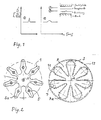
- a Sauglamellenplatine 1 is shown, of the metal carrier seal 3 is enclosed outside.
- the Sauglamellenplatine here has seven suction lamellae 5, but in principle may have any number of suction lamellae.
- suction lamellae 5 the Saugventilstopp stops 5a at the free end, each pierced to the gas passage of the Allow compressed gas, and extend radially from the center axis A of the Compressor to the outside.
- recesses 7a provided for the Saugventilstopps. Again equidistant behind the Contour of the recesses 7 is reset a metal bead 11 in the metal carrier seal imprinted.
- the illustrated preferred embodiment has another Beading 13 at a small distance from the outer edge of the component to the sealing effect to increase the atmosphere.
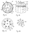
- Fig. 3A shows an associated cylinder block 15 in the plan view. It is the radial orientation of the Sauglamellenan Farbs 5a shown as the approximately sickle-shaped Contour that follows the contour of cylinder bores 17.
- the Sauglamellenanelle 5a diametrically opposite, is on the circumference of the cylinder bores 17 in the other one each incorporated in the surface of the cylinder head Immersion area 5b provided for the Sauglamelle.
- Fig. 3A shows a central bore 19 and a circumferential groove 21, e.g. to insert a optional O-ring for (additional) sealing to the outside.
- FIG. 3B shows a longitudinal section through the overall arrangement of cylinder head, Sauglamellenplatine, valve plate and the end of a pressure plate along the section line A-A in Fig. 3A.
- FIG. 3B shows a longitudinal section through the overall arrangement of cylinder head, Sauglamellenplatine, valve plate and the end of a pressure plate along the section line A-A in Fig. 3A.
- the Valve plate is designated by numeral 25, and in this is a Saugventilbohrung 27 and a pressure valve bore 29 to recognize.
- valve plate 25 and a Pressure plate 31 is shown in plan view.
- Fig. 4B is also the arrangement of the pressure plates 23 of the pressure plate 31 extending radially from the inside to the outside.
- a center hole 33 of the pressure plate 31 is used for their screwing.
- the pressure valve bores 29 a valve seat groove and a chamfer (not separately designated) have.
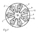
- Fig. 5 is shown how the Sauglamellenplatine 1 (axially at the same level lying) in the metal carrier seal 3 is fitted.
- the entire board suitably positioned (e.g., by 2 pins), defined on the adjacent components.
- Another alternative is to single in an outer metal carrier seal Fit suction lamellae. This eliminates the small comparatively worse sealed area through which the suction lamellae led the Sauglamellenplatine become. In this case, instead of the Sauglamellenplatine 7 individual Sauglamellen to assemble.
- FIGS. 6 and 7 each show a board-seal composite part 100 and 100 ', respectively the o.g. first aspect of the invention is used instead of the usual formed as separate parts components valve plate and Sauglamellenplatine (or "suction valve").
- FIGS. 8A and 8B show possible embodiments in schematic cross-sectional views mentioned beads, these figures are self-explanatory and do not require further explanation.
- a compressor in which a sealing arrangement of the type described above is used, is characterized in a first advantageous embodiment of the invention in that a piston of the compressor is designed such that its top in the top dead center in the height range of the Sauglamellenplatine and metal carrier seal or the circuit board Seal composite part lies. In a further advantageous embodiment, it is designed for operation with a refrigerant, in particular CO 2 .
- Another expedient embodiment of the compressor is characterized by a compression of the sealing arrangement between the cylinder block and valve plate ensuring screwing in the peripheral region, wherein the number of screws by the number of cylinders or twice the number of cylinders is fixed, and / or a central screw with a screw in the center axis or more screws near the center axis.
- the proposed seal configurations are also suitable for a "screwless" design, in which the compressor can be closed or also welded, for example, by means of a cover screw connection.
Landscapes
- Engineering & Computer Science (AREA)
- Mechanical Engineering (AREA)
- General Engineering & Computer Science (AREA)
- Compressor (AREA)
Applications Claiming Priority (2)
| Application Number | Priority Date | Filing Date | Title |
|---|---|---|---|
| DE2003143340 DE10343340A1 (de) | 2003-09-18 | 2003-09-18 | Dichtanordnung eines Kompressors |
| DE10343340 | 2003-09-18 |
Publications (2)
| Publication Number | Publication Date |
|---|---|
| EP1517038A2 true EP1517038A2 (fr) | 2005-03-23 |
| EP1517038A3 EP1517038A3 (fr) | 2009-07-22 |
Family
ID=34177826
Family Applications (1)
| Application Number | Title | Priority Date | Filing Date |
|---|---|---|---|
| EP04021366A Withdrawn EP1517038A3 (fr) | 2003-09-18 | 2004-09-08 | Système d'étanchéité pour compresseurs |
Country Status (2)
| Country | Link |
|---|---|
| EP (1) | EP1517038A3 (fr) |
| DE (1) | DE10343340A1 (fr) |
Cited By (1)
| Publication number | Priority date | Publication date | Assignee | Title |
|---|---|---|---|---|
| FR2869956A1 (fr) * | 2004-05-10 | 2005-11-11 | Sanden Corp | Compresseurs du type a plaque inclinee et systemes de conditionnement d'air comprenant ces compresseurs |
Families Citing this family (2)
| Publication number | Priority date | Publication date | Assignee | Title |
|---|---|---|---|---|
| DE102015120862A1 (de) * | 2015-12-01 | 2017-06-01 | Elringklinger Ag | Ventillamelle |
| DE102021128196A1 (de) | 2021-10-28 | 2023-05-04 | Aircom Automotive Sp. z o.o. Sp. k. | Auslassventil für einen Kompressor |
Citations (5)
| Publication number | Priority date | Publication date | Assignee | Title |
|---|---|---|---|---|
| US4416190A (en) * | 1979-12-13 | 1983-11-22 | Diesel Kiki Co., Ltd. | Seal for compressor |
| DE4446302A1 (de) * | 1993-12-27 | 1995-06-29 | Toyoda Automatic Loom Works | Taumelscheibenkompressor mit Druckschwankungsdämpfer |
| DE19755241A1 (de) * | 1996-12-17 | 1998-06-25 | Zexel Corp | Kühlmittelverdichter |
| DE19962121A1 (de) * | 1998-12-22 | 2000-07-13 | Luk Fahrzeug Hydraulik | Anordnung zur Abdichtung im Bereich zwischen dem Zylinderblock und der Ventilplatte eines Kompressors |
| EP1288497A2 (fr) * | 2001-08-28 | 2003-03-05 | Kabushiki Kaisha Toyota Jidoshokki | Système d'étanchéité pour compresseurs |
Family Cites Families (7)
| Publication number | Priority date | Publication date | Assignee | Title |
|---|---|---|---|---|
| JPS5820394B2 (ja) * | 1978-01-24 | 1983-04-22 | サンデン株式会社 | 流体吸排装置 |
| US4172696A (en) * | 1978-04-17 | 1979-10-30 | Borg-Warner Corporation | Low stress suction or discharge reed valve for compressor |
| DE4234746A1 (de) * | 1992-10-15 | 1994-04-21 | Braun Ag | Pumpe für Haushaltsgeräte |
| US5528976A (en) * | 1993-11-24 | 1996-06-25 | Kabushiki Kaisha Toyoda Jidoshokki Seisakusho | Swash plate type compressor with bearing assembly |
| JP3429100B2 (ja) * | 1995-03-22 | 2003-07-22 | 株式会社豊田自動織機 | 両頭斜板式圧縮機 |
| JP4910184B2 (ja) * | 2000-06-20 | 2012-04-04 | 株式会社ヴァレオジャパン | 往復式冷媒圧縮機 |
| JP2002070739A (ja) * | 2000-08-30 | 2002-03-08 | Zexel Valeo Climate Control Corp | 往復式冷媒圧縮機 |
-
2003
- 2003-09-18 DE DE2003143340 patent/DE10343340A1/de not_active Ceased
-
2004
- 2004-09-08 EP EP04021366A patent/EP1517038A3/fr not_active Withdrawn
Patent Citations (5)
| Publication number | Priority date | Publication date | Assignee | Title |
|---|---|---|---|---|
| US4416190A (en) * | 1979-12-13 | 1983-11-22 | Diesel Kiki Co., Ltd. | Seal for compressor |
| DE4446302A1 (de) * | 1993-12-27 | 1995-06-29 | Toyoda Automatic Loom Works | Taumelscheibenkompressor mit Druckschwankungsdämpfer |
| DE19755241A1 (de) * | 1996-12-17 | 1998-06-25 | Zexel Corp | Kühlmittelverdichter |
| DE19962121A1 (de) * | 1998-12-22 | 2000-07-13 | Luk Fahrzeug Hydraulik | Anordnung zur Abdichtung im Bereich zwischen dem Zylinderblock und der Ventilplatte eines Kompressors |
| EP1288497A2 (fr) * | 2001-08-28 | 2003-03-05 | Kabushiki Kaisha Toyota Jidoshokki | Système d'étanchéité pour compresseurs |
Cited By (1)
| Publication number | Priority date | Publication date | Assignee | Title |
|---|---|---|---|---|
| FR2869956A1 (fr) * | 2004-05-10 | 2005-11-11 | Sanden Corp | Compresseurs du type a plaque inclinee et systemes de conditionnement d'air comprenant ces compresseurs |
Also Published As
| Publication number | Publication date |
|---|---|
| DE10343340A1 (de) | 2005-04-14 |
| EP1517038A3 (fr) | 2009-07-22 |
Similar Documents
| Publication | Publication Date | Title |
|---|---|---|
| DE3927589C2 (de) | Dichtungseinheit | |
| DE19736431C2 (de) | Statische Dichtungsanordnung | |
| EP2732164B1 (fr) | Pompe à engrenages | |
| EP2280198B1 (fr) | Unité de fermeture pour un ensemble cylindre piston | |
| DE19523283B4 (de) | Pumpe, insbesondere Hochdruckpumpe für eine Kraftstoffeinspritzvorrichtung eines Verbrennungsmotors | |
| DE102008013778A1 (de) | Dichtung | |
| EP1721095A1 (fr) | Dispositif d'etancheite pour un moteur pivotant radial | |
| DE102019132729A1 (de) | Sickendichtung | |
| AT15377U1 (de) | Zylinderkopfdeckel für einen kältemittelkompressor | |
| DE102012207078A1 (de) | Zahnradmaschine mit einer Axialdichtung, die sich in den Bereich der radialen Außenoberfläche des zugeordneten Lagerkörpers erstreckt | |
| EP1340010B1 (fr) | Joint plat pour un moteur a pistons ou une machine-outil | |
| EP1517038A2 (fr) | Système d'étanchéité pour compresseurs | |
| DE10231920B4 (de) | Mehrlagen-Membran | |
| EP2228543B1 (fr) | Vérin rotatif | |
| DE102015120862A1 (de) | Ventillamelle | |
| DE102011018346B4 (de) | Rotationskolbenmotor und Abdichtungsverfahren für einen Rotationskolbenmotor | |
| DE102008037672B4 (de) | Kolbenverdichter, insbesondere Kältemittelverdichter | |
| DE19808251A1 (de) | Kompressor, insbesondere für eine Klimaanlage eines Kraftfahrzeugs | |
| WO2011003680A1 (fr) | Joint d'étanchéité plat | |
| DE10028768A1 (de) | Ventil zum Steuern von Flüssigkeiten | |
| EP1592902B1 (fr) | Garniture d'etancheite plate | |
| DE202020104630U1 (de) | Tandemdichtungssystem und hydraulischer Stellantrieb | |
| EP4337861A1 (fr) | Pompe à pistons radiaux, en particulier compresseur à pistons radiaux | |
| DE10316651B4 (de) | Taumelscheibenkompressor für eine Fahrzeug-Klimaanlage mit Spalt zwischen Gehäuse und Zylinderblock | |
| DE19859062C2 (de) | Anordnung zur Abdichtung im Bereich zwischen dem Zylinderblock und der Ventilplatte eines Kompressors |
Legal Events
| Date | Code | Title | Description |
|---|---|---|---|
| PUAI | Public reference made under article 153(3) epc to a published international application that has entered the european phase |
Free format text: ORIGINAL CODE: 0009012 |
|
| AK | Designated contracting states |
Kind code of ref document: A2 Designated state(s): AT BE BG CH CY CZ DE DK EE ES FI FR GB GR HU IE IT LI LU MC NL PL PT RO SE SI SK TR |
|
| AX | Request for extension of the european patent |
Extension state: AL HR LT LV MK |
|
| RAP1 | Party data changed (applicant data changed or rights of an application transferred) |
Owner name: VALEO COMPRESSOR EUROPE GMBH |
|
| PUAL | Search report despatched |
Free format text: ORIGINAL CODE: 0009013 |
|
| AK | Designated contracting states |
Kind code of ref document: A3 Designated state(s): AT BE BG CH CY CZ DE DK EE ES FI FR GB GR HU IE IT LI LU MC NL PL PT RO SE SI SK TR |
|
| AX | Request for extension of the european patent |
Extension state: AL HR LT LV MK |
|
| AKX | Designation fees paid | ||
| STAA | Information on the status of an ep patent application or granted ep patent |
Free format text: STATUS: THE APPLICATION IS DEEMED TO BE WITHDRAWN |
|
| 18D | Application deemed to be withdrawn |
Effective date: 20100122 |
|
| REG | Reference to a national code |
Ref country code: DE Ref legal event code: 8566 |