EP1517038A2 - Compressor sealing system - Google Patents
Compressor sealing system Download PDFInfo
- Publication number
- EP1517038A2 EP1517038A2 EP04021366A EP04021366A EP1517038A2 EP 1517038 A2 EP1517038 A2 EP 1517038A2 EP 04021366 A EP04021366 A EP 04021366A EP 04021366 A EP04021366 A EP 04021366A EP 1517038 A2 EP1517038 A2 EP 1517038A2
- Authority
- EP
- European Patent Office
- Prior art keywords
- sealing
- seal
- sauglamellenplatine
- valve plate
- sealing arrangement
- Prior art date
- Legal status (The legal status is an assumption and is not a legal conclusion. Google has not performed a legal analysis and makes no representation as to the accuracy of the status listed.)
- Withdrawn
Links
Images


Classifications
-
- F—MECHANICAL ENGINEERING; LIGHTING; HEATING; WEAPONS; BLASTING
- F04—POSITIVE - DISPLACEMENT MACHINES FOR LIQUIDS; PUMPS FOR LIQUIDS OR ELASTIC FLUIDS
- F04B—POSITIVE-DISPLACEMENT MACHINES FOR LIQUIDS; PUMPS
- F04B39/00—Component parts, details, or accessories, of pumps or pumping systems specially adapted for elastic fluids, not otherwise provided for in, or of interest apart from, groups F04B25/00 - F04B37/00
- F04B39/10—Adaptations or arrangements of distribution members
- F04B39/1073—Adaptations or arrangements of distribution members the members being reed valves
-
- F—MECHANICAL ENGINEERING; LIGHTING; HEATING; WEAPONS; BLASTING
- F04—POSITIVE - DISPLACEMENT MACHINES FOR LIQUIDS; PUMPS FOR LIQUIDS OR ELASTIC FLUIDS
- F04B—POSITIVE-DISPLACEMENT MACHINES FOR LIQUIDS; PUMPS
- F04B27/00—Multi-cylinder pumps specially adapted for elastic fluids and characterised by number or arrangement of cylinders
- F04B27/08—Multi-cylinder pumps specially adapted for elastic fluids and characterised by number or arrangement of cylinders having cylinders coaxial with, or parallel or inclined to, main shaft axis
- F04B27/10—Multi-cylinder pumps specially adapted for elastic fluids and characterised by number or arrangement of cylinders having cylinders coaxial with, or parallel or inclined to, main shaft axis having stationary cylinders
- F04B27/1009—Distribution members
-
- F—MECHANICAL ENGINEERING; LIGHTING; HEATING; WEAPONS; BLASTING
- F04—POSITIVE - DISPLACEMENT MACHINES FOR LIQUIDS; PUMPS FOR LIQUIDS OR ELASTIC FLUIDS
- F04B—POSITIVE-DISPLACEMENT MACHINES FOR LIQUIDS; PUMPS
- F04B27/00—Multi-cylinder pumps specially adapted for elastic fluids and characterised by number or arrangement of cylinders
- F04B27/08—Multi-cylinder pumps specially adapted for elastic fluids and characterised by number or arrangement of cylinders having cylinders coaxial with, or parallel or inclined to, main shaft axis
- F04B27/10—Multi-cylinder pumps specially adapted for elastic fluids and characterised by number or arrangement of cylinders having cylinders coaxial with, or parallel or inclined to, main shaft axis having stationary cylinders
- F04B27/1036—Component parts, details, e.g. sealings, lubrication
- F04B27/1081—Casings, housings
-
- F—MECHANICAL ENGINEERING; LIGHTING; HEATING; WEAPONS; BLASTING
- F04—POSITIVE - DISPLACEMENT MACHINES FOR LIQUIDS; PUMPS FOR LIQUIDS OR ELASTIC FLUIDS
- F04B—POSITIVE-DISPLACEMENT MACHINES FOR LIQUIDS; PUMPS
- F04B39/00—Component parts, details, or accessories, of pumps or pumping systems specially adapted for elastic fluids, not otherwise provided for in, or of interest apart from, groups F04B25/00 - F04B37/00
- F04B39/10—Adaptations or arrangements of distribution members
- F04B39/1066—Valve plates
-
- F—MECHANICAL ENGINEERING; LIGHTING; HEATING; WEAPONS; BLASTING
- F05—INDEXING SCHEMES RELATING TO ENGINES OR PUMPS IN VARIOUS SUBCLASSES OF CLASSES F01-F04
- F05C—INDEXING SCHEME RELATING TO MATERIALS, MATERIAL PROPERTIES OR MATERIAL CHARACTERISTICS FOR MACHINES, ENGINES OR PUMPS OTHER THAN NON-POSITIVE-DISPLACEMENT MACHINES OR ENGINES
- F05C2253/00—Other material characteristics; Treatment of material
- F05C2253/12—Coating
Definitions
- the invention relates to an arrangement for sealing in the region between the cylinder block and the valve plate of a compressor, preferably a CO 2 compressor for the air conditioning system of a motor vehicle, wherein between the cylinder block and the valve plate, a Sauglamellenplatine is arranged, the suction valves formed in the cylinder block associated displacement chambers includes.
- Compressors with seals in the area between the cylinder block and the Valve plate exist in a variety of embodiments.
- Compressors of the type referred to comprise a housing which is one of outside powered compressor unit.
- the example formed as axial piston pump unit again comprises at least a piston which is reciprocable in a cylinder block.
- Such a compressor is equipped with several pistons, which at Rotation of a swash plate or swash plate in the direction of its longitudinal axis and to be moved.
- the compressor comprises one on a drive shaft supported swash plate to perform a uniform rotational movement.
- the Swash plate is movable with a variety of in a cylinder block back and forth Coupled piston, wherein the cylinder / piston assembly for compression a refrigerant gas is used.
- the pistons can also be double-acting Pistons act.
- Sauglamellenplatine with integrated valves (suction lamellae) without special sealing measures arranged. Rather, according to the prior art due to the at Assembly produced surface pressure sealed. On the other hand, it is also the Use of simple gaskets (such as metal gaskets or metal carrier gaskets) between Sauglamellenplatine and cylinder block known e.g. optional with a thin elastomeric coating are provided to increase the sealing effect. In no case between Sauglamellenplatine and valve seat plate with a sealed seal, as the Sauglamellenplatine to the valve plate must lie in order to fulfill different functions (sealing completion of the Suction hole, defined stop - e.g. for reasons of strength for warranty a long life).
- CO 2 will be used as a refrigerant.
- the metallic sealing surface can open, which leads to leaks, especially to internal leaks. This then leads to a loss of power of the compressor. It can be assumed that this behavior will also occur with conventional gaskets (metal gaskets or metal carrier gaskets).
- Conventional O-rings can not be used in most areas of an air conditioning compressor for CO 2 application due to various technical issues (explosive decompression, very high or very low temperature problems, etc.).
- Applicant's JP 2002 070739 proposes a compressor for the use of the refrigerant CO 2 . Described is a seal arrangement between Sauglamellenplatine and cylinder block, whereby the leakage between these two components is prevented.
- a metal carrier seal is used here, which has an elastomer coating and in certain areas, for example the cylinder bores in the cylinder block surrounding area, to increase the sealing effect provides sealing beads, which are introduced by forming in the metal carrier seal.
- Such seals are known from other fields of mechanical engineering.
- a similar seal is also described in DE 199 62 121 A1.
- the order is configured such that between the cylinder block and the Sauglamellenplatine a flat sealing body is arranged and that the sealing body for Board towards a ring around the respective cylinder space extending survey or thickening.
- This sealing body has the Sauglamellenplatine out circular around the respective cylinder space extending elevation, thickening or the like.
- the proposed survey or the like is for Board and thus also formed to the valve plate and should during assembly cause its local increase in surface pressure.
- a possible voltage curve in such a seal is qualitative shown: While in the working plane of the metal carrier seal a strong increase in voltage is achieved (2), there is a significant attenuation / flattening the profile on the top of the suction plate (depending on the thickness of the Sauglamellenblechs and configuration of the bead). Especially in the shortest connection between cylinder bores, the intermediate webs in the cylinder block, the Pressing provided by the bead in the area between the valve plate and the Sauglamellenplatine have no influence, as a result of the compression forces the deformations of the components (lifting the valve plate) in this area are particularly high and the housing clamping by the screwing, e.g. more effective outdoors.
- the invention is based essentially on the two last-mentioned patents relating to the prior art (CO 2 compressors). Reference will also be made to the usual metal carrier gaskets modified with corresponding gaskets and corresponding coatings, particularly elastomeric coatings. However, the different designs in this area are not the subject of this invention.
- the invention includes in a first aspect the essential idea, that the e.g. Elastomer-coated metal carrier seal directly between valve plate and cylinder block seals without the effect (sealing effect, function etc.) is influenced or attenuated by the Sauglamellenplatine.
- the sealing system can be in the valve plate or integrated into the suction lamella board or as a curing during the assembly process or crosslinking sealing system on the interfaces on the Sauglamellenplatine be applied. It is also proposed Sauglamellenplatine and metal support gasket to unite a component and all sealing functions essentially integrate into this.
- the internal leakage, e.g. between the valve plate and the suction plate is thereby that reduces a sealing system in valve plate and / or suction plate (Suction valve) integrated or incorporated or a sealing material or adhesive / sealant during the assembly process is applied to the sealing surfaces.
- These Seal provides e.g. a seal of the cylinder bores to each other and the seal safe from tax holes.
- the seal is advantageously without additional sealing elements (e.g., a flat gasket, o-rings or another metal bead seal). These would increase the assembly costs and possibly extend the dead space of the compressor, which is negative would affect the performance of the compressor.
- the seal to the atmosphere can according to the prior art with metal bead seals or O-rings.
- the sealing effect is achieved according to the first aspect of the invention, that on the suction lamellae board or on the valve plate a soft material, e.g. an elastomer or soft metal, e.g. Tin or copper, applied becomes.
- This soft material can then bumps, which in the macro and Micro range, e.g. caused by the machining of the parts, compensate and ensure a good tightness.
- the soft material can either large area or even partially on the interfaces as a sealing layer be applied.
- the layer which produces the sealing effect can have any desired thickness.
- the goal is to make the layer thin in order to simplify the application process design and reduce material consumption. Further, with a thin Density layer of the dead space is not extended, indicating high performance the compressor is important.
- a partial or surface bonding of the components is proposed.
- the application of the adhesive can be integrated into the assembly process be.
- the parts can be made with a hardening or cross-linking adhesive or else only be provided with a pasty sealing material.
- the sealing system is applied directly in the area of the sealing surface and reacts there too (curing, networking).
- reaction sealing systems such as. Polyurethane foam systems, preferred.
- the used Sealing system which is applied during assembly, can be in liquid but also be applied in thixotropic form.
- the parts to be joined and sealed can be at the same time be positioned. This allows positioning pins and the corresponding Drilling is eliminated, resulting in an additional significant simplification represents the manufacturing process.
- the proposed according to the second aspect of the invention novel component includes the function of the suction plate and the metal bead seal, inclusive All sealing functions, integrated, also provide the complete seal to the cylinder block as to the valve plate, but also towards the environment, for sure.
- the number of This reduces sealing points, reduces the number of parts as well as the design the sealing surfaces and acreage simplified.
- the integration of the seal has a significant cost advantage, since in the best case no further component needed becomes. Thus, the achieved energy gain compared to low costs.
- the pads can be made simpler. So can e.g. Bags for receiving sealing elements or for receiving the Saugventillammelle account for the Zylinderblockflansch Structure, which is a significant simplification represents the manufacturing process.
- the control bores and for the external sealing of the compressor its environment in turn, no further seals are necessary.
- one or more Bead (s) which surrounds the areas to be sealed (enclose) attached be.
- These can / can be combined with or without elastomer or Soft metal coating be introduced into the Sauglamellenplatine.
- the or each Beading leads to a local increase in pressing pressures. This will cause the leakage currents prevented. It is specifically suggested that around the cylinder bores and control bores are introduced beads, which is a local pressure increase and increasing the pressure generated.
- the suction plate on the valve plate e.g. through positioning pins, can be omitted, as the Sauglamellenplatine on the positioning pins is clearly defined in position in the housing.
- the Sauglamellenplatine is directly in the Metal carrier gasket fitted, so it is quasi axially on a same level like the metal carrier gasket. Because they are the same within close tolerances Height as the metal carrier seal, and both parts are very thin-walled, It is easily possible, both parts even at low height differences so in To compress the compressor components valve plate and cylinder block that the respective Functions are sufficiently ensured.
- a Sauglamellenplatine 1 is shown, of the metal carrier seal 3 is enclosed outside.
- the Sauglamellenplatine here has seven suction lamellae 5, but in principle may have any number of suction lamellae.
- suction lamellae 5 the Saugventilstopp stops 5a at the free end, each pierced to the gas passage of the Allow compressed gas, and extend radially from the center axis A of the Compressor to the outside.
- recesses 7a provided for the Saugventilstopps. Again equidistant behind the Contour of the recesses 7 is reset a metal bead 11 in the metal carrier seal imprinted.
- the illustrated preferred embodiment has another Beading 13 at a small distance from the outer edge of the component to the sealing effect to increase the atmosphere.
- Fig. 3A shows an associated cylinder block 15 in the plan view. It is the radial orientation of the Sauglamellenan Farbs 5a shown as the approximately sickle-shaped Contour that follows the contour of cylinder bores 17.
- the Sauglamellenanelle 5a diametrically opposite, is on the circumference of the cylinder bores 17 in the other one each incorporated in the surface of the cylinder head Immersion area 5b provided for the Sauglamelle.
- Fig. 3A shows a central bore 19 and a circumferential groove 21, e.g. to insert a optional O-ring for (additional) sealing to the outside.
- FIG. 3B shows a longitudinal section through the overall arrangement of cylinder head, Sauglamellenplatine, valve plate and the end of a pressure plate along the section line A-A in Fig. 3A.
- FIG. 3B shows a longitudinal section through the overall arrangement of cylinder head, Sauglamellenplatine, valve plate and the end of a pressure plate along the section line A-A in Fig. 3A.
- the Valve plate is designated by numeral 25, and in this is a Saugventilbohrung 27 and a pressure valve bore 29 to recognize.
- valve plate 25 and a Pressure plate 31 is shown in plan view.
- Fig. 4B is also the arrangement of the pressure plates 23 of the pressure plate 31 extending radially from the inside to the outside.
- a center hole 33 of the pressure plate 31 is used for their screwing.
- the pressure valve bores 29 a valve seat groove and a chamfer (not separately designated) have.
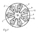
- Fig. 5 is shown how the Sauglamellenplatine 1 (axially at the same level lying) in the metal carrier seal 3 is fitted.
- the entire board suitably positioned (e.g., by 2 pins), defined on the adjacent components.
- Another alternative is to single in an outer metal carrier seal Fit suction lamellae. This eliminates the small comparatively worse sealed area through which the suction lamellae led the Sauglamellenplatine become. In this case, instead of the Sauglamellenplatine 7 individual Sauglamellen to assemble.
- FIGS. 6 and 7 each show a board-seal composite part 100 and 100 ', respectively the o.g. first aspect of the invention is used instead of the usual formed as separate parts components valve plate and Sauglamellenplatine (or "suction valve").
- FIGS. 8A and 8B show possible embodiments in schematic cross-sectional views mentioned beads, these figures are self-explanatory and do not require further explanation.
- a compressor in which a sealing arrangement of the type described above is used, is characterized in a first advantageous embodiment of the invention in that a piston of the compressor is designed such that its top in the top dead center in the height range of the Sauglamellenplatine and metal carrier seal or the circuit board Seal composite part lies. In a further advantageous embodiment, it is designed for operation with a refrigerant, in particular CO 2 .
- Another expedient embodiment of the compressor is characterized by a compression of the sealing arrangement between the cylinder block and valve plate ensuring screwing in the peripheral region, wherein the number of screws by the number of cylinders or twice the number of cylinders is fixed, and / or a central screw with a screw in the center axis or more screws near the center axis.
- the proposed seal configurations are also suitable for a "screwless" design, in which the compressor can be closed or also welded, for example, by means of a cover screw connection.
Abstract
Description
Die Erfindung betrifft eine Anordnung zur Abdichtung im Bereich zwischen dem Zylinderblock und der Ventilplatte eines Kompressors, vorzugsweise eines CO2-Kompressors für die Klimaanlage eines Kraftfahrzeugs, wobei zwischen dem Zylinderblock und der Ventilplatte eine Sauglamellenplatine angeordnet ist, die den im Zylinderblock ausgebildeten Verdrängungsräumen zugeordnete Saugventile umfasst.The invention relates to an arrangement for sealing in the region between the cylinder block and the valve plate of a compressor, preferably a CO 2 compressor for the air conditioning system of a motor vehicle, wherein between the cylinder block and the valve plate, a Sauglamellenplatine is arranged, the suction valves formed in the cylinder block associated displacement chambers includes.
Kompressoren, mit Abdichtungen im Bereich zwischen dem Zylinderblock und der Ventilplatte existieren in den unterschiedlichsten Ausführungsformen.Compressors, with seals in the area between the cylinder block and the Valve plate exist in a variety of embodiments.
Zum Stand der Technik werden beispielhaft folgende Druckschriften genannt:
DE 196 11 004 A1, DE 44 41 721 C2, JP 2002070739 und DE 199 62 121 A1.The state of the art is exemplified by the following publications:
DE 196 11 004 A1, DE 44 41 721 C2, JP 2002070739 and DE 199 62 121 A1.
In der Regel handelt es sich hierbei um Kompressoren mit Zylinderblock und Ventilplatte, bei denen zwischen dem Zylinderblock und der Ventilplatte (Ventilsitzplatte sowohl für Sauglamellen als auch Drucklamellen) eine dünne Sauglamellenplatine angeordnet ist, die den im Zylinderblock ausgebildeten Zylinderräumen zugeordnete (Saug-)Ventile umfasst.As a rule, these are compressors with cylinder block and valve plate, in which between the cylinder block and the valve plate (valve seat plate for both suction louvers and pressure fins) a thin suction lamella plate is arranged, which associated with the cylinders formed in the cylinder block chambers Includes (suction) valves.
Kompressoren des angesprochenen Typs umfassen ein Gehäuse, welches eine von außerhalb angetriebene Verdichter- bzw. Pumpeneinheit einschließt. Die beispielsweise als Axialkolbenpumpe ausgebildete Pumpeneinheit umfasst wiederum mindestens einen Kolben, der in einem Zylinderblock hin und her bewegbar ist. Üblicherweise ist ein solcher Kompressor mit mehreren Kolben ausgestattet, die bei Drehung einer Taumelscheibe oder Schrägscheibe in Richtung ihrer Längsachse hin und her bewegt werden. Compressors of the type referred to comprise a housing which is one of outside powered compressor unit. The example formed as axial piston pump unit again comprises at least a piston which is reciprocable in a cylinder block. Usually Such a compressor is equipped with several pistons, which at Rotation of a swash plate or swash plate in the direction of its longitudinal axis and to be moved.
Beispielhaft wird dazu auf die DE 44 41 721 A1 und die DE 196 11 004 A1 verwiesen. Gemäß DE 44 41 721 A1 umfasst der Kompressor eine auf einer Antriebswelle gestützte Schrägscheibe, um eine einheitliche Drehbewegung auszuführen. Die Schrägscheibe ist mit einer Vielzahl von in einem Zylinderblock hin und her bewegbaren Kolben gekoppelt, wobei die Zylinder/Kolben-Anordnung zum Komprimieren eines Kältemittelgases dient. Bei den Kolben kann es sich auch um doppelt wirkende Kolben handeln.For example, reference is made to DE 44 41 721 A1 and DE 196 11 004 A1. According to DE 44 41 721 A1, the compressor comprises one on a drive shaft supported swash plate to perform a uniform rotational movement. The Swash plate is movable with a variety of in a cylinder block back and forth Coupled piston, wherein the cylinder / piston assembly for compression a refrigerant gas is used. The pistons can also be double-acting Pistons act.
Zwischen den Arbeitsräumen der Zylinder und der Ventilplatte ist eine Sauglamellenplatine mit integrierten Ventilen (Sauglamellen) ohne besondere Dichtungsmaßnahmen angeordnet. Vielmehr wird gemäß Stand der Technik aufgrund der bei der Montage erzeugten Flächenpressung gedichtet. Es ist aber andererseits auch der Einsatz einfacher Flachdichtungen (z.B. Metalldichtungen oder Metallträgerdichtungen) zwischen Sauglamellenplatine und Zylinderblock bekannt, die z.B. optional mit einer dünnen Elastomerbeschichtung versehen sind, um die Dichtwirkung zu steigern. In keinem Fall wird zwischen Sauglamellenplatine und Ventilsitzplatte mit einer separaten Dichtung gedichtet, da die Sauglamellenplatine an der Ventilplatte aufliegen muss, um verschiedene Funktionen zu erfüllen (dichtender Abschluss der Saugbohrung, definierter Anschlag - z.B. aus Festigkeitsgründen zur Gewährleistung einer hohen Lebensdauer).Between the working chambers of the cylinder and the valve plate is a Sauglamellenplatine with integrated valves (suction lamellae) without special sealing measures arranged. Rather, according to the prior art due to the at Assembly produced surface pressure sealed. On the other hand, it is also the Use of simple gaskets (such as metal gaskets or metal carrier gaskets) between Sauglamellenplatine and cylinder block known e.g. optional with a thin elastomeric coating are provided to increase the sealing effect. In no case between Sauglamellenplatine and valve seat plate with a sealed seal, as the Sauglamellenplatine to the valve plate must lie in order to fulfill different functions (sealing completion of the Suction hole, defined stop - e.g. for reasons of strength for warranty a long life).
Weitere bekannte Abdichtungen für den Bereich zwischen Zylinderblock und Sauglamelle werden durch den Einsatz von O-Ringen realisiert. Prinzipiell ist diese Form der Abdichtung gegenüber der in den zitierten Schriften dargestellten Applikation in allen Bereichen des Kompressors denkbar. Z.B. wird oft zur Atmosphäre hin, d.h. nach außen, zwischen den Bauteilen in herkömmlicher Weise mit O-Ringen gedichtet, es gibt aber auch Lösungen mit Flachdichtungen.Other known seals for the area between the cylinder block and Sauglamelle are realized through the use of O-rings. In principle, this form the seal against the application shown in the cited documents conceivable in all areas of the compressor. For example, is often going to the atmosphere, i.e. to the outside, between the components conventionally sealed with O-rings, But there are also solutions with flat gaskets.
Die zuvor beschriebenen Abdichtungen beziehen sich auf das Kältemittel R134a, welches Stand der Technik ist.The seals described above refer to the refrigerant R134a, which state of the art is.
Im Zusammenhang mit zukünftigen Kompressoren wird CO2 als Kältemittel eingesetzt werden. Bei den dort auftretenden sehr hohen Betriebsdrücken kann sich die metallische Dichtfläche öffnen, wodurch es zu Leckagen, insbesondere zu internen Leckagen, kommt. Dies führt dann zu einem Leistungsverlust des Verdichters. Es ist anzunehmen, dass auch bei konventionellen Flachdichtungen (Metalldichtungen oder Metallträgerdichtungen) dieses Verhalten auftreten wird. Herkömmliche O-Ringe können aufgrund verschiedener technischer Probleme (explosive Dekompression, Probleme mit sehr hohen oder sehr niedrigen Temperaturen etc.) in den meisten Bereichen eines Klimakompressors für die CO2-Anwendung nicht eingesetzt werden.In the context of future compressors, CO 2 will be used as a refrigerant. At the very high operating pressures occurring there, the metallic sealing surface can open, which leads to leaks, especially to internal leaks. This then leads to a loss of power of the compressor. It can be assumed that this behavior will also occur with conventional gaskets (metal gaskets or metal carrier gaskets). Conventional O-rings can not be used in most areas of an air conditioning compressor for CO 2 application due to various technical issues (explosive decompression, very high or very low temperature problems, etc.).
Mit der JP 2002 070739 der Anmelderin wird ein Kompressor für den Einsatz des Kältemittels CO2 vorgeschlagen. Beschrieben wird eine Dichtungsanordnung zwischen Sauglamellenplatine und Zylinderblock, wodurch die Leckage zwischen diesen beiden Bauteilen verhindert wird. Bevorzugt wird hier eine Metallträgerdichtung benutzt, die eine Elastomerbeschichtung aufweist und in bestimmten Bereichen, so z.B. die in dem Zylinderblock befindlichen Zylinderbohrungen umgebenden Bereich, zur Steigerung der Dichtwirkung Dichtsicken bereitstellt, die durch Umformen in die Metallträgerdichtung eingebracht werden. Solche Dichtungen sind aus anderen Bereichen des Maschinenbaus bekannt.Applicant's JP 2002 070739 proposes a compressor for the use of the refrigerant CO 2 . Described is a seal arrangement between Sauglamellenplatine and cylinder block, whereby the leakage between these two components is prevented. Preferably, a metal carrier seal is used here, which has an elastomer coating and in certain areas, for example the cylinder bores in the cylinder block surrounding area, to increase the sealing effect provides sealing beads, which are introduced by forming in the metal carrier seal. Such seals are known from other fields of mechanical engineering.
Eine ähnliche Abdichtung wird auch in der DE 199 62 121 A1 beschrieben. Die Anordnung ist derart konfiguriert, dass zwischen dem Zylinderblock und der Sauglamellenplatine ein flacher Dichtkörper angeordnet ist und dass der Dichtkörper zur Platine hin eine ringförmig um den jeweiligen Zylinderraum verlaufende Erhebung oder Verdickung aufweist. Dieser Dichtkörper weist zur Sauglamellenplatine hin eine kreisringförmig um den jeweiligen Zylinderraum verlaufende Erhebung, Verdickung oder dergleichen auf. Die vorgesehene Erhebung oder dergleichen ist zur Platine und somit auch zur Ventilplatte hin ausgebildet und soll bei der Montage seine lokale Erhöhung der Flächenpressung bewirken.A similar seal is also described in DE 199 62 121 A1. The order is configured such that between the cylinder block and the Sauglamellenplatine a flat sealing body is arranged and that the sealing body for Board towards a ring around the respective cylinder space extending survey or thickening. This sealing body has the Sauglamellenplatine out circular around the respective cylinder space extending elevation, thickening or the like. The proposed survey or the like is for Board and thus also formed to the valve plate and should during assembly cause its local increase in surface pressure.
Entgegen der sonst üblichen Vorgehensweise, nämlich zwischen den abzudichtenden Bauteilen - also zwischen der Sauglamellenplatine und der Ventilplatte - eine Abdichtung durch Flächenpressung, zuzüglich einer Außenabdichtung mittels O-Ring, vorzusehen, hat man hier die Abdichtungsmaßnahme zwischen dem Zylinderblock und der Platine, d.h. von der Ventilplatte abgewandt, vorgesehen.Contrary to the usual procedure, namely between the sealed Components - ie between the Sauglamellenplatine and the valve plate - a Sealing by surface pressure, plus an outer seal by means of O-ring, provide, you have here the sealing measure between the cylinder block and the board, i. facing away from the valve plate provided.
Die somit erreichte Erhöhung der Flächenpressung dichtet in erster Linie zwischen Zylinderblock und Ventilplatte anderseits wird möglicherweise auch eine leichte Verbesserung zwischen Sauglamellenplatine und Ventilplatte erreicht. Letztendlich soll hier der Effekt genutzt werden, wonach sich die erhöhte Flächenpressung eventuell auch durch die dünne Sauglamellenplatine hindurch auf die Berührfläche von Sauglamellenplatine und Ventilplatte überträgt.The thus achieved increase in surface pressure seals primarily between Cylinder block and valve plate on the other hand may also be a light Improvement achieved between Sauglamellenplatine and valve plate. At long last Here, the effect should be used, after which the increased surface pressure may also through the thin Sauglamellenplatine through on the contact surface of suction plate and valve plate transmits.
Problematisch bei dieser Lösung ist im wesentlichen, dass der Bereich zwischen Sauglamellenplatine und der Ventilplatte nicht in gleicher Qualität gedichtet wird, wie der Bereich zwischen Sauglamellenplatine und Zylinderblock. In der Tat kann die Sicke mit einem elastisches Rückformverhalten auch eine erhöhte Flächenpressung an der abgewandten Seite der Platine bereitstellen, dabei ist aber die Sauglamellenplatine auf die Abdichtung abzustimmen, d.h. sie muss sehr geringe Dicke haben sein. Übliche Dicken für Sauglamellen liegen z.B. im Bereich 0,2 bis 0,35 mm. Die Qualität der Abdichtung wird sich zudem bezüglich beider Seiten der Sauglamellenplatine erheblich unterscheiden.The problem with this solution is essentially that the area between Suction plate and the valve plate is not sealed in the same quality, like the area between suction plate and cylinder block. In fact, can the bead with an elastic recovery behavior also increased surface pressure provide on the opposite side of the board, but here is the Sauglamellenplatine to match the seal, i. she needs very small thickness have to be. Typical thicknesses for suction lamellae are e.g. in the range 0.2 to 0.35 mm. The quality of the seal will also be on both sides of the Significantly different suction plate.
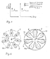
In Fig. 1 ist ein möglicher Spannungsverlauf bei einer solchen Abdichtung qualitativ gezeigt: Während in der Wirkebene der Metallträgerdichtung eine starke Spannungserhöhung erreicht wird (2), so erfolgt eine erhebliche Dämpfung/ Abflachung des Profils an der Oberseite der Sauglamellenplatine (je nach Stärke des Sauglamellenblechs und Konfiguration der Sicke). Insbesondere in der kürzesten Verbindung zwischen Zylinderbohrungen, den Zwischenstegen im Zylinderblock, wird die Pressung bereitgestellt, durch die Sicke im Bereich zwischen der Ventilplatte und der Sauglamellenplatine keinen Einfluss mehr haben, da infolge der Kompressionskräfte die Deformationen der Bauteile (Abheben der Ventilplatte) in diesem Bereich besonders hoch sind und die Gehäuseverspannung durch die Verschraubungen z.B. eher im Außenbereich wirksam ist. In Fig. 1, a possible voltage curve in such a seal is qualitative shown: While in the working plane of the metal carrier seal a strong increase in voltage is achieved (2), there is a significant attenuation / flattening the profile on the top of the suction plate (depending on the thickness of the Sauglamellenblechs and configuration of the bead). Especially in the shortest connection between cylinder bores, the intermediate webs in the cylinder block, the Pressing provided by the bead in the area between the valve plate and the Sauglamellenplatine have no influence, as a result of the compression forces the deformations of the components (lifting the valve plate) in this area are particularly high and the housing clamping by the screwing, e.g. more effective outdoors.
Es ist demnach inkonsequent, im Bereich der Sauglamellenplatine und des Zylinderblocks eine solche hochwertige Abdichtung bereitzustellen, im Bereich zwischen Sauglamellenplatine und Ventilplatte dagegen energetisch schädliche Leckageströme zuzulassen. Weiterhin werden verschiedene Verbindungsbohrungen, die in der Regel die Ventilplatte, die Sauglamellenplatine und den Zylinderblock durchdringen, nicht gleichwertig gedichtet. Für diese Bohrungen muss einerseits der Spalt zwischen Ventilplatte und Sauglamellenplatine gedichtet werden, anderseits muss der Spalt zwischen dem Zylinderblock und der Sauglamellenplatine gasdicht sein. In der Regel sind das die folgenden Bohrungen oder Durchbrechungen:
- Bohrung für die Gasführung vom Triebwerksraum zur Saugkammer des Verdichters (für die Regelung);
- Bohrung für die Gasführung von der Hochdruckseite zum Triebwerksraum des Verdichters (für die Regelung);
- Bohrungen, um z.B. im Bereich des Zylinderkopfes vom Druckgas abgeschiedenes Öl in den Kurbelraum zurückzuführen (Ölrückführung).
- Bore for the gas supply from the engine room to the suction chamber of the compressor (for the control);
- Bore for the gas supply from the high pressure side to the engine room of the compressor (for the control);
- Holes, for example in the area of the cylinder head of the compressed gas separated oil in the crankcase due (oil return).
Sowohl im Bereich der Zylinderbohrungen als auch im Bereich der erwähnten Bohrungen für kommunizierende Druckniveaus oder die Ölabscheidung müssen diese Durchbrechungen, insbesondere auch gegeneinander gedichtet werden. Weiterhin müssen diese Durchbrüche aber auch eine exzellente Abdichtung gegenüber der Atmosphäre aufweisen.Both in the area of the cylinder bores as well as in the area of the mentioned holes for communicating pressure levels or oil separation these must Breakthroughs, especially against each other sealed. Farther But these breakthroughs must also be an excellent seal against the Atmosphere.
Wie bereits angesprochen wurde, ist ein weiteres Problem die Abdichtung des Spaltes zwischen Ventilplatte und Sauglamellenplatine. Im Prinzip könnte durch Einlegen einer weiteren gleichartigen Metallträgerdichtung der Bereich ausreichend abgedichtet werden. Problematisch ist hierbei allerdings, dass neben dem Aufwand, den ein weiteres Bauteil erfordert, der Ventilsitz der Sauglamellenplatine auf der Ventilplatte stark beeinträchtigt würde, so dass man mit erheblichen Funktionsstörungen rechnen müsste. Die Sauglamellenplatine muss eine möglichst ebene, glatte Auflagefläche auf der Ventilplatte vorfinden und außerhalb der Zylinderbohrungen fest zwischen den Bauteilen eingespannt sein. Durch Einbringung einer weiteren Metallträgerdichtung würde man die Sauglamellenplatine quasi von der Ventilplattenoberfläche separieren, so dass ihre Funktion (z.B. auch Vermeidung von Leckage) nicht mehr sichergestellt wäre. Auch würde zusätzlich Schadraum entstehen, da jede "Blechschicht" den Kolben von der Ventilplatte separiert.As already mentioned, another problem is the sealing of the Gap between valve plate and Sauglamellenplatine. In principle, could through Inserting another similar metal carrier seal the area sufficient be sealed. The problem here is, however, that in addition to the effort, which requires a further component, the valve seat of the Sauglamellenplatine The valve plate would be severely compromised, leaving one with significant malfunction would have to count. The Sauglamellenplatine must be as level as possible, smooth contact surface on the valve plate and outside the cylinder bores be firmly clamped between the components. By introducing another Metal carrier gasket would make the suction lamella plate almost from the valve plate surface so that their function (e.g., avoidance of Leakage) would no longer be ensured. In addition, dead space would also arise since each "sheet metal layer" separates the piston from the valve plate.
Die Erfindung geht im wesentlichen von den beiden zuletzt genannten Patentschriften zum Stand der Technik (CO2-Kompressoren) aus. Es wird auch Bezug auf die üblichen Metallträgerdichtungen genommen, die mit entsprechenden Dichtsicken und entsprechenden Beschichtungen, insbesondere Elastomerbeschichtungen modifiziert sind. Die unterschiedlichen Bauformen in diesem Bereich sind jedoch nicht Gegenstand dieser Erfindung.The invention is based essentially on the two last-mentioned patents relating to the prior art (CO 2 compressors). Reference will also be made to the usual metal carrier gaskets modified with corresponding gaskets and corresponding coatings, particularly elastomeric coatings. However, the different designs in this area are not the subject of this invention.
Es ist Aufgabe der Erfindung, eine einfache und kostengünstige Anordnung zur. Abdichtung im Bereich zwischen dem Zylinderblock und der Ventilplatte eines Kompressors, speziell eines CO2-Kompressors, anzugeben, mit der interne Leckagen und somit auf interne Leckagen zurückzuführende Leistungsverluste des Kompressors zumindest weitgehend vermieden sind.It is an object of the invention to provide a simple and inexpensive arrangement for. Seal in the area between the cylinder block and the valve plate of a compressor, especially a CO 2 compressor to specify, with the internal leakage and thus attributable to internal leaks power losses of the compressor are at least largely avoided.
Diese Aufgabe wird gelöst durch eine Dichtanordnung mit den Merkmalen des Anspruchs
1. Zweckmäßige Fortbildungen des Erfindungsgedankens sind Gegenstand
der abhängigen Ansprüche.This object is achieved by a sealing arrangement with the features of the
Die Erfindung schließt unter einem ersten Aspekt den wesentlichen Gedanken ein, dass die z.B. elastomerbeschichtete Metallträgerdichtung direkt zwischen Ventilplatte und Zylinderblock dichtet, ohne dass die Wirkung (Dichtwirkung, Funktion etc.) durch die Sauglamellenplatine beeinflusst oder abgeschwächt wird. Vorgeschlagen wird ein Dichtsystem zwischen Ventilplatte und Saugventil und eine Abdichtung zwischen Zylinderblock und Ventilplatte eines Axialkolbenverdichters, um die Leckageströme zu reduzieren. Das Dichtungssystem kann in die Ventilplatte oder in die Sauglamellenplatine integriert sein oder beim Montageprozess als aushärtendes oder vernetzendes Dichtsystem auf die Grenzflächen an der Sauglamellenplatine aufgebracht werden. Ferner wird vorgeschlagen, Sauglamellenplatine und Metallträgerdichtung zu einem Bauteil zu vereinigen und alle Dichtfunktionen im wesentlichen in dieses zu integrieren. The invention includes in a first aspect the essential idea, that the e.g. Elastomer-coated metal carrier seal directly between valve plate and cylinder block seals without the effect (sealing effect, function etc.) is influenced or attenuated by the Sauglamellenplatine. proposed is a sealing system between valve plate and suction valve and a seal between cylinder block and valve plate of an axial piston compressor to to reduce the leakage currents. The sealing system can be in the valve plate or integrated into the suction lamella board or as a curing during the assembly process or crosslinking sealing system on the interfaces on the Sauglamellenplatine be applied. It is also proposed Sauglamellenplatine and metal support gasket to unite a component and all sealing functions essentially integrate into this.
Mit der Erfindung wird das Leistungsvermögen und der Wirkungsgrad von Axialkolbenverdichtern, speziell von CO2-Kompressoren, wie sie in Fahrzeugen eingesetzt werden, deutlich erhöht.With the invention, the performance and efficiency of axial piston compressors, especially of CO 2 compressors, as used in vehicles, significantly increased.
Die interne Leckage, z.B. zwischen der Ventilplatte und der Sauglamelle, wird dadurch reduziert, dass ein Dichtsystem in Ventilplatte und/oder Sauglamellenplatine (Saugventil) integriert bzw. eingebracht oder aber ein Dichtwerkstoff bzw. Kleb/Dichtstoff beim Montageprozess auf die Dichtflächen aufgetragen wird. Diese Dichtung stellt z.B. eine Abdichtung der Zylinderbohrungen zueinander und die Abdichtung von Steuerbohrungen sicher. Dadurch wird in vorteilhafter Weise die Abdichtung ohne zusätzliche Dichtelemente (z.B. eine Flachdichtung, O-Ringe oder weitere Metallsickendichtung) erreicht. Diese würden den Montageaufwand erhöhen und unter Umständen den Schadraum des Verdichters erweitern, was sich negativ auf das Leistungsvermögen des Verdichters auswirken würde. Die Abdichtung zur Atmosphäre kann dabei nach dem Stand der Technik mit Metallsickendichtungen oder O-Ringen ausgeführt sein.The internal leakage, e.g. between the valve plate and the suction plate is thereby that reduces a sealing system in valve plate and / or suction plate (Suction valve) integrated or incorporated or a sealing material or adhesive / sealant during the assembly process is applied to the sealing surfaces. These Seal provides e.g. a seal of the cylinder bores to each other and the seal safe from tax holes. As a result, the seal is advantageously without additional sealing elements (e.g., a flat gasket, o-rings or another metal bead seal). These would increase the assembly costs and possibly extend the dead space of the compressor, which is negative would affect the performance of the compressor. The seal to the atmosphere can according to the prior art with metal bead seals or O-rings.
Die Dichtwirkung wird gemäß dem ersten Aspekt der Erfindung dadurch erzielt, dass auf die Sauglamellenplatine oder auf die Ventilplatte ein weicher Werkstoff, z.B. ein Elastomer oder weiches Metall, wie z.B. Zinn oder Kupfer, aufgebracht wird. Dieser weiche Werkstoff kann dann Unebenheiten, welche im Makro- und Mikrobereich liegen können, z.B. von der Bearbeitung der Teile verursacht werden, ausgleichen und eine gute Dichtheit sicherstellen. Der weiche Werkstoff kann entweder großflächig oder aber auch partiell auf die Grenzflächen als Dichtschicht aufgebracht werden.The sealing effect is achieved according to the first aspect of the invention, that on the suction lamellae board or on the valve plate a soft material, e.g. an elastomer or soft metal, e.g. Tin or copper, applied becomes. This soft material can then bumps, which in the macro and Micro range, e.g. caused by the machining of the parts, compensate and ensure a good tightness. The soft material can either large area or even partially on the interfaces as a sealing layer be applied.
Die Schicht, welche die Dichtwirkung erzeugt, kann eine beliebige Dicke aufwiesen. Ziel ist es aber, die Schicht dünn zu gestalten, um den Auftragprozess einfach zu gestalten und den Werkstoffverbrauch zu reduzieren. Ferner wird mit einer dünnen Dichtschicht der Schadraum nicht erweitert, was für ein hohes Leistungsvermögen des Verdichters wichtig ist. The layer which produces the sealing effect can have any desired thickness. The goal, however, is to make the layer thin in order to simplify the application process design and reduce material consumption. Further, with a thin Density layer of the dead space is not extended, indicating high performance the compressor is important.
Als weitere Variante wird ein partielles oder flächiges Verkleben der Bauteile vorgeschlagen. Das Aufbringen des Klebers kann dabei in den Montageprozess integriert sein. Die Teile können dabei mit einem aushärtenden oder vernetzenden Kleber oder aber nur mit einem pastösen Dichtungswerkstoff versehen sein. Das Dichtungssystem wird dabei direkt im Bereich der Dichtfläche aufgetragen und reagiert dort auch (Aushärten, Vernetzen). Dabei wird die Verwendung von Reaktions-Dichtungssystemen, wie z.B. Polyurethanschaumsystemen, bevorzugt. Das verwendete Dichtungssystem, welches bei der Montage aufgebracht wird, kann in flüssiger aber auch in thixotroper Form aufgebracht werden.As a further variant, a partial or surface bonding of the components is proposed. The application of the adhesive can be integrated into the assembly process be. The parts can be made with a hardening or cross-linking adhesive or else only be provided with a pasty sealing material. The sealing system is applied directly in the area of the sealing surface and reacts there too (curing, networking). The use of reaction sealing systems, such as. Polyurethane foam systems, preferred. The used Sealing system, which is applied during assembly, can be in liquid but also be applied in thixotropic form.
Beim Verkleben können die zu fügenden und zu dichtenden Teile gleichzeitig zueinander positioniert werden. Dadurch können Positionierungsstifte und die entsprechenden Bohrungen entfallen, was eine zusätzliche wesentliche Vereinfachung des Herstellungsprozesses darstellt.When gluing, the parts to be joined and sealed can be at the same time be positioned. This allows positioning pins and the corresponding Drilling is eliminated, resulting in an additional significant simplification represents the manufacturing process.
Das gemäß dem zweiten Aspekt der Erfindung vorgeschlagene neuartige Bauteil, das die Funktion der Sauglamellenplatine und der Metallsickendichtung, inklusive aller Dichtfunktionen, integriert, stellt ebenso die vollständige Dichtung zum Zylinderblock wie zur Ventilplatte, aber auch zur Umgebung hin, sicher. Die Anzahl der Dichtstellen wird dadurch reduziert, die Teileanzahl verringert sowie die Gestaltung der Dichtflächen und Anbauflächen vereinfacht. Die Integration der Dichtung hat einen deutlichen Kostenvorteil, da im besten Fall kein weiteres Bauteil benötigt wird. So stehen dem erzielten energetischen Gewinn geringe Kosten gegenüber. Des weiteren können die Anschlussflächen einfacher gestaltet werden. So können z.B. Taschen zur Aufnehme von Dichtelementen oder zur Aufnehme der Saugventillammelle an der Zylinderblockflanschfläche entfallen, was eine deutliche Vereinfachung des Fertigungsprozesses darstellt. Für die Abdichtung der einzelnen Zylinderräume, der Steuerbohrungen und für die Außenabdichtung des Verdichters an seine Umwelt sind wiederum keine weiteren Dichtungen notwendig.The proposed according to the second aspect of the invention novel component, This includes the function of the suction plate and the metal bead seal, inclusive All sealing functions, integrated, also provide the complete seal to the cylinder block as to the valve plate, but also towards the environment, for sure. The number of This reduces sealing points, reduces the number of parts as well as the design the sealing surfaces and acreage simplified. The integration of the seal has a significant cost advantage, since in the best case no further component needed becomes. Thus, the achieved energy gain compared to low costs. Furthermore, the pads can be made simpler. So can e.g. Bags for receiving sealing elements or for receiving the Saugventillammelle account for the Zylinderblockflanschfläche, which is a significant simplification represents the manufacturing process. For the sealing of the individual cylinder chambers, the control bores and for the external sealing of the compressor its environment, in turn, no further seals are necessary.
Alternativ ist das vorgeschlagene Dichtsystem auch im Bereich Zylinderblock oder Drucklamellenplatine und allen weiteren internen und ggf. externen Dichtstellen einzusetzen. Alternatively, the proposed sealing system in the cylinder block or Pressure lamella board and all other internal and possibly external sealing points use.
Neben der Elastomer- oder Weichmetallbeschichtung können auch eine oder mehrere Sicke(n), welche die abzudichtenden Bereiche umschließt (umschließen) angebracht sein. Diese kann/können in Kombination mit oder ohne Elastomer- oder Weichmetallbeschichtung in die Sauglamellenplatine eingebracht sein. Die oder jede Sicke führt zu einer lokalen Erhöhung der Pressdrücke. Dadurch werden die Leckageströme unterbunden. Vorgeschlagen wird speziell, dass um die Zylinderbohrungen und Steuerbohrungen Sicken eingebracht sind, die eine lokale Drucküberhöhung und Erhöhung der Pressung erzeugt. Auf eine zusätzliche genaue Positionierung der Sauglamellenplatine auf der Ventilplatte, z.B. durch Positionierungsstifte, kann verzichtet werden, da die Sauglamellenplatine über die Positionierungsstifte im Gehäuse in ihrer Position eindeutig definiert wird.In addition to the elastomer or soft metal coating, one or more Bead (s) which surrounds the areas to be sealed (enclose) attached be. These can / can be combined with or without elastomer or Soft metal coating be introduced into the Sauglamellenplatine. The or each Beading leads to a local increase in pressing pressures. This will cause the leakage currents prevented. It is specifically suggested that around the cylinder bores and control bores are introduced beads, which is a local pressure increase and increasing the pressure generated. On an additional accurate positioning the suction plate on the valve plate, e.g. through positioning pins, can be omitted, as the Sauglamellenplatine on the positioning pins is clearly defined in position in the housing.
Alle vorgeschlagenen Dichtungsmöglichkeiten können einzeln und in Kombination verwendet werden und werden einzeln und in Kombination beansprucht.All proposed sealing options can be used individually and in combination are used and claimed individually and in combination.
Weitere Vorteile der Erfindung in ihren oben genannten Varianten bzw. von zweckmäßigen Ausführungsführen derselben sind die folgenden:
- Dadurch, dass zwischen der Sauglamellenplatine und dem Zylinderblock keine Metallträgerdichtung liegt, kann die Kante des Zylinderblocks, über den die Sauglamelle infolge Ventilöffnung gebogen wird, leicht dem Biegeverlauf der Lamelle angepasst werden, was sich vorteilhaft bzgl. der Lebensdauer äußert.
- Aus dem gleichen Grund kann die (optionale) Sicke auch sehr nah an die Außenkontur der Zylinderbohrung geführt werden, was den Schadraum und die Deformation der Ventilplatte leicht verringert.
- Bei der Ausführung, wo Metallträgerdichtung und Sauglamelle ineinander liegen, wird geringfügig die Verdichterbaulänge verringert.
- Durch Ineinanderlegen von Metallträgerdichtung und Sauglamellenplatine wird die Höhe des schädlichen Raumes verringert. Prinzipiell kann der Kolben zwar zumindest teilweise in diesen Bereich hineingeführt werden, praktisch ergibt sich aber durch mehr Bauteile (und Toleranzen) in diesem Bereich ein größerer schädlicher Raum.
- Characterized in that there is no metal carrier seal between the Sauglamellenplatine and the cylinder block, the edge of the cylinder block over which the suction plate is bent due to valve opening, easily be adapted to the bending curve of the blade, which manifests itself advantageous in terms of life.
- For the same reason, the (optional) bead can also be guided very close to the outer contour of the cylinder bore, which slightly reduces the dead space and the deformation of the valve plate.
- In the version where the metal carrier seal and the suction lamella are intertwined, the compactor length is slightly reduced.
- By interleaving the metal carrier seal and the suction lamella plate, the height of the harmful space is reduced. In principle, although the piston can be guided into this area at least partially, practically more components (and tolerances) in this area result in a larger, damaging space.
In einer erfindungsgemäßen Ausführung wird die Sauglamellenplatine direkt in die Metallträgerdichtung eingepasst, sie liegt damit quasi axial auf einem gleichen Niveau wie die Metallträgerdichtung. Da sie im Rahmen enger Toleranzen die gleiche Höhe wie die Metallträgerdichtung aufweist, und beide Teile sehr dünnwandig sind, ist es problemlos möglich, beide Teile auch bei geringen Höhenunterschieden so in den Verdichterbauteilen Ventilplatte und Zylinderblock zu verspannen, dass die jeweiligen Funktionen hinreichend gewährleistet sind.In an embodiment of the invention, the Sauglamellenplatine is directly in the Metal carrier gasket fitted, so it is quasi axially on a same level like the metal carrier gasket. Because they are the same within close tolerances Height as the metal carrier seal, and both parts are very thin-walled, It is easily possible, both parts even at low height differences so in To compress the compressor components valve plate and cylinder block that the respective Functions are sufficiently ensured.
Vorteile und Zweckmäßigkeiten der Erfindung ergeben sich im übrigen aus den abhängigen Ansprüchen sowie der nachfolgenden Beschreibung von Ausführungsbeispielen anhand der Figuren. Von diesen zeigen:
- Fig. 1
- eine grafische Darstellung des Spannungsverlaufes in einer herkömmlichen Dichtanordnung,
- Fig. 2
- als Ausführungsbeispiel der Erfindung eine Dichtanordnung mit einer die Sauglamellenplatine umschließenden Metallträgerdichtung (in Draufsicht),
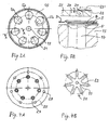
- Fig.
3A und 3B - eine Draufsicht des Zylinderblocks bzw. eine ausschnittweise Querschnittsdarstellung der zugehörigen Dichtanordnung bei der Ausführungsform nach Fig. 2,
- Fig. 4A und 4B
- Ventilplatte und zugehörigen Druckventilstop bei dieser Ausführungsform, in Draufsicht,
- Fig. 5
- die Dichtanordnung aus Fig. 2 im montierten Zustand, in Draufsicht,
- Fig. 6
- ein Platinen-Dichtungs-Verbundteil einer Dichtanordnung gemäß einer weiteren Ausführungsform der Erfindung,
- Fig. 7
- ein gegenüber der Ausführung nach Fig. 6 modifiziertes Platinen-Dichtungs-Verbundteil gemäß einer noch anderen Ausführungsform der Erfindung und
- Fig. 8A und 8B
- schematische Querschnittsdarstellungen von bei der Ausführungsform nach Fig. 7 verwendbaren Sicken-Konfigurationen.
- Fig. 1
- a graphical representation of the voltage curve in a conventional sealing arrangement,
- Fig. 2
- as an embodiment of the invention, a sealing arrangement with a Sauglamellenplatine enclosing metal carrier seal (in plan view),
- FIGS. 3A and 3B
- a top view of the cylinder block and a fragmentary cross-sectional view of the associated sealing arrangement in the embodiment of FIG. 2,
- FIGS. 4A and 4B
- Valve plate and associated pressure valve stop in this embodiment, in plan view,
- Fig. 5
- 2 in the assembled state, in plan view,
- Fig. 6
- a board-sealing composite part of a sealing arrangement according to another embodiment of the invention,
- Fig. 7
- a comparison with the embodiment of FIG. 6 modified board-seal composite part according to yet another embodiment of the invention and
- Figs. 8A and 8B
- schematic cross-sectional views of usable in the embodiment of Fig. 7 bead configurations.
In Fig. 2 ist eine Sauglamellenplatine 1 dargestellt, die von der Metallträgerdichtung
3 außen umschlossen wird. Die Sauglamellenplatine weist hier sieben Sauglamellen
5 auf, kann aber im Prinzip beliebig viele Sauglamellen aufweisen. In diesem
Ausführungsbeispiel sind die Sauglamellen 5, die Saugventilstopp-Anschläge
5a am freien Ende aufweisen, jeweils durchbrochen, um den Gasdurchtritt des
Druckgases zu ermöglichen, und erstrecken sich radial von der Mittenachse A des
Kompressors nach außen.In Fig. 2, a
Aussparungen 7 der Metallträgerdichtung 3, die bezüglich Zwischenstegen 9 um die
Sauglamellen der Sauglamellenplatine herumfassen, ergeben sich in etwa äquidistant
der Kontur des Saugventilstopps der Zylinderbohrung (partiell) und folgen jeweils
annähernd den Konturen der Sauglamellen (sowie auch der Kontur der Zylinderbohrung)
bis zu einem zentralen Bereich. Am radial äußeren Ende sind Aussparungen
7a für die Saugventilstopps vorgesehen. Wiederum äquidistant hinter die
Kontur der Aussparungen 7 zurückgesetzt ist eine Metallsicke 11 in die Metallträgerdichtung
eingeprägt. Die gezeigte bevorzugte Ausführungsform weist eine weitere
Sicke 13 in geringem Abstand vom Außenrand des Bauteils auf, um die Dichtwirkung
gegenüber der Atmosphäre zu steigern.
Fig. 3A stellt einen zugehörigen Zylinderblock 15 in der Draufsicht dar. Es ist die
radiale Ausrichtung des Sauglamellenanschlags 5a dargestellt, als die etwa sichelförmige
Kontur, die sich an die Kontur von Zylinderbohrungen 17 anschließt. Den
Sauglamellenanschlägen 5a diametral gegenüberliegend, ist am Umfang der Zylinderbohrungen
17 im übrigen jeweils ein in die Oberfläche des Zylinderkopfes eingearbeiteter
Eintauchbereich 5b für die Sauglamelle vorgesehen. Weiterhin ist in
Fig. 3A eine Mittenbohrung 19 sowie eine Umfangsnut 21, z.B. zum Einlegen eines
optionalen O-Ringes zur (zusätzlichen) Abdichtung nach Außen zu erkennen.Fig. 3A shows an associated
Fig. 3B zeigt eine Längsschnittdarstellung durch die Gesamtanordnung aus Zylinderkopf,
Sauglamellenplatine, Ventilplatte und das Ende einer Drucklamelle längs
der Schnittlinie A-A in Fig. 3A. Hier werden schematisch - in Art einer synoptischen
Darstellung - die Stellungen einer Sauglamelle 5 beim Ausschieben des Gases
(durchgezogene Linie) bzw. beim Ansaugen (dargestellt als punktierte Biegelinie
7') und einer Drucklamelle 23 beim Ansaugen (schraffiert dargestellt) bzw. beim
Ausschicken (gestrichelt dargestellt und mit Ziffer 23' bezeichnet) gezeigt. Die
Ventilplatte ist mit Ziffer 25 bezeichnet, und in dieser sind eine Saugventilbohrung
27 und eine Druckventilbohrung 29 zu erkennen. Im übrigen ist in Fig. 3B zu erkennen,
dass die Metallträgerdichtung 3 (Fig. 2, rechte Seite) in gleicher Höhe mit
der Sauglamellenplatine 1 liegt.3B shows a longitudinal section through the overall arrangement of cylinder head,
Sauglamellenplatine, valve plate and the end of a pressure plate along
the section line A-A in Fig. 3A. Here are schematic - in the manner of a synoptic
Representation - the positions of a
Der Vollständigkeit halber sind in Fig. 4A und 4B die Ventilplatte 25 und eine
Drucklamellenplatine 31 in der Draufsicht dargestellt. In diesem Ausführungsbeispiel
(Fig. 4B) ist auch die Anordnung der Drucklamellen 23 der Drucklamellenplatine
31 radial von innen nach außen verlaufend. Eine Mittenbohrung 33 der Drucklamellenplatine
31 dient zu deren Verschraubung. Im übrigen sind in den Figuren
3A und 4A an der Peripherie jeweils vorgesehene Bohrungen zur Verschraubung
der Bauteile im Interesse der Übersichtlichkeit der Darstellungen fortgelassen. In
Fig. A ist zu erkennen, dass die Druckventilbohrungen 29 eine Ventil-Sitznut und
eine Anfasung (nicht gesondert bezeichnet) aufweisen.For completeness, in Fig. 4A and 4B, the
In diesem Fall sind deshalb Aussparungen oder Bohrungen in der Sauglamellenplatine erforderlich, weil die Sauglamellen und Drucklamellen an beiden Seiten der Ventilplatte quasi übereinander liegen. Es sei aber betont, dass es sich hierbei nur um ein Ausführungsbeispiel handelt und prinzipiell ganz andere Anordnungen ebenfalls möglich sind.In this case, therefore, recesses or holes in the Sauglamellenplatine required because the suction louvers and pressure lamellae on both sides of the Valve plate, so to speak, one above the other. But it should be stressed that this is only an embodiment and in principle quite different arrangements also possible are.
In Fig. 5 ist dargestellt, wie die Sauglamellenplatine 1 (axial auf gleichem Niveau liegend) in die Metallträgerdichtung 3 eingepasst ist. Hierbei wird die gesamte Platine, geeignet (z.B. durch 2 Stifte), an den angrenzenden Bauteilen definiert positioniert.In Fig. 5 is shown how the Sauglamellenplatine 1 (axially at the same level lying) in the metal carrier seal 3 is fitted. Here, the entire board, suitably positioned (e.g., by 2 pins), defined on the adjacent components.
Eine alternative Ausführung sieht vor, dass die beiden in Abbildung 2 dargestellten Teile ein integrales Teil sind, was aber bei dieser Konfiguration natürlich infolge von zu beschichtenden und nicht zu beschichtenden Bereichen zu einem erhöhten Fertigungsaufwand führen würde.An alternative embodiment provides that the two shown in Figure 2 Parts are an integral part, but of course in this configuration areas to be coated and non-coated are increased Production costs would result.
Eine weitere Alternative besteht darin, in eine äußere Metallträgerdichtung einzelne
Sauglamellen einzupassen. Damit entfällt der kleine vergleichsweise schlechter
gedichtete Bereich, durch den die Sauglamellen der Sauglamellenplatine geführt
werden. In diesem Fall hätte man statt der Sauglamellenplatine 7 einzelne Sauglamellen
zu montieren.Another alternative is to single in an outer metal carrier seal
Fit suction lamellae. This eliminates the small comparatively worse
sealed area through which the suction lamellae led the Sauglamellenplatine
become. In this case, instead of the
Bevorzugt ist im übrigen, dass im Bereich der Verdichtermittelachse eine stärkere zentrale Verschraubung vorgesehen ist, die durch entsprechende Verspannung in diesem Bereich den kleinen, nicht durch die Sicke gedichteten Bereich, zusätzlich beaufschlagt.Moreover, it is preferred that in the region of the compressor center axis a stronger central gland is provided by the appropriate tension in In this area, the small, not by the bead-sealed area, in addition applied.
Fig. 6 und 7 zeigen jeweils ein Platinen-Dichtungs-Verbundteil 100 bzw. 100' gemäß
dem o.g. ersten Aspekt der Erfindung zum Einsatz anstelle der üblicherweise
als separate Teile ausgebildeten Komponenten Ventilplatte und Sauglamellenplatine
(bzw. "Saugventil"). Während bei der in Fig. 6 gezeigten ersten Ausführung dieses
Verbundteils vor dem Zusammenfügen einer Sauglamellenplatine bzw. eines
Saugventils 101 und einer Ventilplatte 103 mit im wesentlichen herkömmlicher
Konfiguration an deren Berührungsfläche vollflächig eine - im montierten Zustand
nicht sichtbare - Dicht- bzw. Klebstoffschicht als einziges Dichtmittel aufgetragen
wurde, sind bei dem Verbundteil 100' nach Fig. 7 um die Sauglamellen 105 herum
Metallsicken 107, um eine zusätzliche Verbindungsbohrung 109 herum eine Metallsicke
111 und um den Außenrand der Sauglamellenplatine herum eine weitere Sicke
113 als zusätzliche Dichtmittel vorgesehen. Es können auch mehrere Verbindungsbohrungen
109 vorhanden sein, deren Dichtung sinnvoll ist. FIGS. 6 and 7 each show a board-seal
Fig. 8A und 8B zeigen in schematischen Querschnittsdarstellungen mögliche Ausführungsformen der erwähnten Sicken, wobei diese Figuren selbsterklärend sind und keiner weiteren Erläuterung bedürfen.FIGS. 8A and 8B show possible embodiments in schematic cross-sectional views mentioned beads, these figures are self-explanatory and do not require further explanation.
Ein Kompressor, bei dem eine Dichtanordnung der oben beschriebenen Art eingesetzt wird, zeichnet sich in einer ersten vorteilhaften Ausführung der Erfindung dadurch aus, dass ein Kolben des Kompressors derart ausgebildet ist, dass seine Oberseite im oberen Todpunkt im Höhenbereich der Sauglamellenplatine und Metallträgerdichtung oder des Platinen-Dichtungs-Verbundteils liegt. In einer weiteren vorteilhaften Ausführung ist er für den Betrieb mit einem Kältemittel, insbesondere CO2, ausgebildet. Eine weitere zweckmäßige Ausführung des Kompressors zeichnet sich aus durch eine die Verpressung der Dichtanordnung zwischen Zylinderblock und Ventilplatte gewährleistende Verschraubung im Umfangsbereich, wobei die Anzahl der Schrauben durch die Anzahl der Zylinder oder die zweifache Anzahl der Zylinder festgelegt ist, und/oder eine zentrale Verschraubung mit einer Schraube in der Mittenachse oder mehreren Schrauben nahe der Mittenachse. Im übrigen ist darauf hinzuweisen, dass die vorgeschlagenen Dichtungskonfigurationen aber auch für eine "schraubenlose" Konstruktion geeignet sind, bei der der Verdichter über eine Deckelverschraubung verschlossen oder z.B. auch verschweißt werden kann.A compressor, in which a sealing arrangement of the type described above is used, is characterized in a first advantageous embodiment of the invention in that a piston of the compressor is designed such that its top in the top dead center in the height range of the Sauglamellenplatine and metal carrier seal or the circuit board Seal composite part lies. In a further advantageous embodiment, it is designed for operation with a refrigerant, in particular CO 2 . Another expedient embodiment of the compressor is characterized by a compression of the sealing arrangement between the cylinder block and valve plate ensuring screwing in the peripheral region, wherein the number of screws by the number of cylinders or twice the number of cylinders is fixed, and / or a central screw with a screw in the center axis or more screws near the center axis. Incidentally, it should be noted that the proposed seal configurations are also suitable for a "screwless" design, in which the compressor can be closed or also welded, for example, by means of a cover screw connection.
Die Ausführung der Erfindung ist nicht auf die oben beschriebenen Ausführungsbeispiele und hervorgehobenen Aspekte beschränkt, sondern ebenso in einer Vielzahl von Abwandlungen - insbesondere Kombinationen der Merkmale einzelner Ausführungsbeispiele - möglich.The embodiment of the invention is not limited to the embodiments described above and highlighted aspects, but also in a variety of ways of modifications - in particular combinations of the characteristics of individual Exemplary embodiments - possible.
Claims (12)
gekennzeichnet durch
eine mindestens abschnittsweise mit einem Elastomeren und/oder Klebstoff beschichtete Metallträgerdichtung, welche die Sauglamellenplatine in radialer Richtung im wesentlichen vollständig umgibt oder mit dieser zusammenhängend als Platinen-Dichtungs-Verbundteil gebildet ist und deren eine Oberfläche mindestens um Zylinder- und wahlweise vorgesehene Verbindungsbohrungen herum in Flächenpressungs-Kontakt mit einer Zylinderblock-Dichtfläche und deren andere Oberfläche in diesen Bereichen in Flächenpressungs-Kontakt mit einer Ventilplatten-Dichtfläche steht.Sealing arrangement of a compressor, for sealing the area between cylinder block and valve plate, where a Sauglamellenplatine is provided,
marked by
an at least partially coated with an elastomer and / or adhesive metal carrier seal which surrounds the Sauglamellenplatine in the radial direction substantially completely or is formed together with this as a sinker-seal composite part and their surface at least one cylinder and optionally provided connection holes around in surface pressure -Contact with a cylinder block sealing surface and the other surface in these areas in surface pressure contact with a valve plate sealing surface is.
dadurch gekennzeichnet, dass
die Metallträgerdichtung die Sauglamellenplatine in deren Ebene umschließt und im wesentlichen die gleiche Höhe wie diese aufweist.Sealing arrangement according to claim 1,
characterized in that
the metal carrier seal surrounds the Sauglamellenplatine in the plane thereof and has substantially the same height as this.
dadurch gekennzeichnet, dass
die Metallträgerdichtung mit einer Art Finger in die Sauglamellenplatine eingreift und die Sauglamellen auch seitlich umschließt.Sealing arrangement according to claim 1 or 2,
characterized in that
The metal carrier seal with a kind of finger engages in the Sauglamellenplatine and the suction lamellae also encloses laterally.
dadurch gekennzeichnet, dass
die Metallträgerdichtung oder das Platinen-Dichtungs-Verbundteil nahe dem Außenumfang Dichtmittel, insbesondere eine umlaufende Sicke, zur Abdichtung gegen die Atmosphäre aufweist.Sealing arrangement according to one of the preceding claims,
characterized in that
the metal support gasket or the board-seal composite part near the outer periphery sealing means, in particular a circumferential bead, for sealing against the atmosphere.
dadurch gekennzeichnet, dass
nahe dem Außenumfang der Ventilplatte ein separater O-Ring zur verbesserten Abdichtung gegen die Atmosphäre auf die Metallträgerdichtung oder das Platinen-Dichtungs-Verbundteil aufgelegt ist.Sealing arrangement according to one of claims 1 to 3,
characterized in that
near the outer periphery of the valve plate, a separate O-ring for improved sealing against the atmosphere is placed on the metal support gasket or the board-seal composite part.
dadurch gekennzeichnet, dass
die Metallträgerdichtung oder das Platinen-Dichtungs-Verbundteil mindestens einen Teil der Zylinder- bzw. Verbindungsbohrungen umgebende Dichtmittel, insbesondere Sicken, zur Abdichtung dieser Zylinder- bzw. Verbindungsbohrungen gegeneinander aufweist.Sealing arrangement according to one of the preceding claims,
characterized in that
the metal carrier seal or the board-sealing composite part has at least a part of the cylinder or connecting holes surrounding sealing means, in particular beads, for sealing these cylinder or connecting holes against each other.
eine zusätzliche Verschraubung der Metallträgerdichtung oder des Platinen-Dichtungs-Verbundteils im zentralen Bereich.Sealing arrangement according to one of the preceding claims, characterized by
additional screwing of the metal carrier gasket or the blanket seal composite in the central area.
dadurch gekennzeichnet, dass
die der Sauglamellenplatine zugewandte Oberfläche der Ventilplatte mindestens um Zylinder- und wahlweise vorgesehene Verbindungsbohrungen herum eine Elastomer- und/oder Klebstoffbeschichtung aufweist, die in Flächenpressungskontakt mit den benachbarten Oberflächenabschnitten der Sauglamellenplatine steht.Sealing arrangement of a compressor, for sealing the area between cylinder block and valve plate, where a Sauglamellenplatine is provided,
characterized in that
the surface of the valve plate facing the suction lamella plate has an elastomer and / or adhesive coating around at least cylinder and selectively provided connection bores which is in surface pressure contact with the adjacent surface portions of the suction lamination plate.
dadurch gekennzeichnet, dass
die Elastomer- und/oder Klebstoffbeschichtung zur Abdichtung der Zylinder- bzw. Verbindungsbohrungen gegeneinander sowie gegen die Atmosphäre ausgebildet ist.Sealing arrangement according to claim 8,
characterized in that
the elastomer and / or adhesive coating for sealing the cylinder or connecting holes against each other and against the atmosphere is formed.
dadurch gekennzeichnet, dass
ein Kolben des Kompressors derart ausgebildet ist, dass seine Oberseite im oberen Todpunkt im Höhenbereich der Sauglamellenplatine und Metallträgerdichtung oder des Platinen-Dichtungs-Verbundteils liegt.Compressor with a sealing arrangement according to one of the preceding claims,
characterized in that
a piston of the compressor is formed such that its upper side is at the top dead center in the height range of the Sauglamellenplatine and metal carrier seal or the sinker-seal composite part.
gekennzeichnet durch
die Ausbildung zum Betrieb mit einem Kältemittel, insbesondere CO2.Compressor with a sealing arrangement according to one of the preceding claims,
marked by
the training for operation with a refrigerant, in particular CO 2 .
gekennzeichnet durch
eine die Verpressung der Dichtanordnung zwischen Zylinderblock und Ventilplatte gewährleistende Verschraubung im Umfangsbereich, wobei die Anzahl der Schrauben durch die Anzahl der Zylinder oder die zweifache Anzahl der Zylinder festgelegt ist, und/oder eine zentrale Verschraubung mit einer Schraube in der Mittenachse oder mehreren Schrauben nahe der Mittenachse.Compressor with a sealing arrangement according to one of the preceding claims,
marked by
a compression of the sealing arrangement between the cylinder block and valve plate ensuring screwing in the peripheral region, wherein the number of screws by the number of cylinders or twice the number of cylinders is fixed, and / or a central screw with a screw in the center axis or more screws near the mid-axis.
Applications Claiming Priority (2)
| Application Number | Priority Date | Filing Date | Title |
|---|---|---|---|
| DE2003143340 DE10343340A1 (en) | 2003-09-18 | 2003-09-18 | Sealing arrangement of a compressor |
| DE10343340 | 2003-09-18 |
Publications (2)
| Publication Number | Publication Date |
|---|---|
| EP1517038A2 true EP1517038A2 (en) | 2005-03-23 |
| EP1517038A3 EP1517038A3 (en) | 2009-07-22 |
Family
ID=34177826
Family Applications (1)
| Application Number | Title | Priority Date | Filing Date |
|---|---|---|---|
| EP04021366A Withdrawn EP1517038A3 (en) | 2003-09-18 | 2004-09-08 | Compressor sealing system |
Country Status (2)
| Country | Link |
|---|---|
| EP (1) | EP1517038A3 (en) |
| DE (1) | DE10343340A1 (en) |
Cited By (1)
| Publication number | Priority date | Publication date | Assignee | Title |
|---|---|---|---|---|
| FR2869956A1 (en) * | 2004-05-10 | 2005-11-11 | Sanden Corp | INCLINED PLATE TYPE COMPRESSORS AND AIR CONDITIONING SYSTEMS COMPRISING THESE COMPRESSORS |
Families Citing this family (2)
| Publication number | Priority date | Publication date | Assignee | Title |
|---|---|---|---|---|
| DE102015120862A1 (en) * | 2015-12-01 | 2017-06-01 | Elringklinger Ag | valve blade |
| DE102021128196A1 (en) | 2021-10-28 | 2023-05-04 | Aircom Automotive Sp. z o.o. Sp. k. | Outlet valve for a compressor |
Citations (5)
| Publication number | Priority date | Publication date | Assignee | Title |
|---|---|---|---|---|
| US4416190A (en) * | 1979-12-13 | 1983-11-22 | Diesel Kiki Co., Ltd. | Seal for compressor |
| DE4446302A1 (en) * | 1993-12-27 | 1995-06-29 | Toyoda Automatic Loom Works | Swashplate compressor with pressure fluctuation damper |
| DE19755241A1 (en) * | 1996-12-17 | 1998-06-25 | Zexel Corp | Coolant compressor |
| DE19962121A1 (en) * | 1998-12-22 | 2000-07-13 | Luk Fahrzeug Hydraulik | Gasket between cylinder block and valve plate of carbon dioxide compressor, for air conditioning installation of road vehicle |
| EP1288497A2 (en) * | 2001-08-28 | 2003-03-05 | Kabushiki Kaisha Toyota Jidoshokki | Sealing mechanism for compressor |
Family Cites Families (7)
| Publication number | Priority date | Publication date | Assignee | Title |
|---|---|---|---|---|
| JPS5820394B2 (en) * | 1978-01-24 | 1983-04-22 | サンデン株式会社 | Fluid suction/drainage device |
| US4172696A (en) * | 1978-04-17 | 1979-10-30 | Borg-Warner Corporation | Low stress suction or discharge reed valve for compressor |
| DE4234746A1 (en) * | 1992-10-15 | 1994-04-21 | Braun Ag | Pump for household appliances |
| US5528976A (en) * | 1993-11-24 | 1996-06-25 | Kabushiki Kaisha Toyoda Jidoshokki Seisakusho | Swash plate type compressor with bearing assembly |
| JP3429100B2 (en) * | 1995-03-22 | 2003-07-22 | 株式会社豊田自動織機 | Double head swash plate type compressor |
| JP4910184B2 (en) * | 2000-06-20 | 2012-04-04 | 株式会社ヴァレオジャパン | Reciprocating refrigerant compressor |
| JP2002070739A (en) * | 2000-08-30 | 2002-03-08 | Zexel Valeo Climate Control Corp | Reciprocating refrigerating compressor |
-
2003
- 2003-09-18 DE DE2003143340 patent/DE10343340A1/en not_active Ceased
-
2004
- 2004-09-08 EP EP04021366A patent/EP1517038A3/en not_active Withdrawn
Patent Citations (5)
| Publication number | Priority date | Publication date | Assignee | Title |
|---|---|---|---|---|
| US4416190A (en) * | 1979-12-13 | 1983-11-22 | Diesel Kiki Co., Ltd. | Seal for compressor |
| DE4446302A1 (en) * | 1993-12-27 | 1995-06-29 | Toyoda Automatic Loom Works | Swashplate compressor with pressure fluctuation damper |
| DE19755241A1 (en) * | 1996-12-17 | 1998-06-25 | Zexel Corp | Coolant compressor |
| DE19962121A1 (en) * | 1998-12-22 | 2000-07-13 | Luk Fahrzeug Hydraulik | Gasket between cylinder block and valve plate of carbon dioxide compressor, for air conditioning installation of road vehicle |
| EP1288497A2 (en) * | 2001-08-28 | 2003-03-05 | Kabushiki Kaisha Toyota Jidoshokki | Sealing mechanism for compressor |
Cited By (1)
| Publication number | Priority date | Publication date | Assignee | Title |
|---|---|---|---|---|
| FR2869956A1 (en) * | 2004-05-10 | 2005-11-11 | Sanden Corp | INCLINED PLATE TYPE COMPRESSORS AND AIR CONDITIONING SYSTEMS COMPRISING THESE COMPRESSORS |
Also Published As
| Publication number | Publication date |
|---|---|
| EP1517038A3 (en) | 2009-07-22 |
| DE10343340A1 (en) | 2005-04-14 |
Similar Documents
| Publication | Publication Date | Title |
|---|---|---|
| DE3927589C2 (en) | Sealing unit | |
| DE19736431C2 (en) | Static sealing arrangement | |
| EP2732164B1 (en) | Gear ring pump | |
| DE19523283B4 (en) | Pump, in particular high-pressure pump for a fuel injection device of an internal combustion engine | |
| DE102008013778A1 (en) | poetry | |
| EP2280198A1 (en) | Closing unit for a piston cylinder device | |
| EP1721095A1 (en) | Sealing device for a radial swivel motor | |
| DE102019132729A1 (en) | Bead seal | |
| AT15377U1 (en) | CYLINDER HEAD COVER FOR A REFRIGERANT COMPRESSOR | |
| DE102012207078A1 (en) | Gear machine with an axial seal, which extends in the region of the radial outer surface of the associated bearing body | |
| EP1340010B1 (en) | Flat seal for a reciprocating piston engine or machine | |
| EP1517038A2 (en) | Compressor sealing system | |
| DE10231920B4 (en) | Multi-layer diaphragm | |
| EP2228543B1 (en) | Oscillating vane motor | |
| DE102015120862A1 (en) | valve blade | |
| DE102011018346B4 (en) | Rotary piston engine and sealing method for a rotary piston engine | |
| DE102008037672B4 (en) | Piston compressor, in particular refrigerant compressor | |
| DE19808251A1 (en) | Vehicle air conditioning compressor | |
| EP2452062A1 (en) | Flat gasket | |
| DE10028768A1 (en) | Valve for controlling liquids has a piezo actuator in an actuator bore, a hydraulic pressure intensifier with first and second pistons and a pressure area between these pistons and metal bellows. | |
| EP1592902B1 (en) | Flat gasket | |
| DE202020104630U1 (en) | Tandem sealing system and hydraulic actuator | |
| EP4337861A1 (en) | Radial piston pump, in particular radial piston compressor | |
| DE10316651B4 (en) | Swash plate compressor for a vehicle air conditioning system with a gap between housing and cylinder block | |
| DE19859062C2 (en) | Arrangement for sealing in the area between the cylinder block and the valve plate of a compressor |
Legal Events
| Date | Code | Title | Description |
|---|---|---|---|
| PUAI | Public reference made under article 153(3) epc to a published international application that has entered the european phase |
Free format text: ORIGINAL CODE: 0009012 |
|
| AK | Designated contracting states |
Kind code of ref document: A2 Designated state(s): AT BE BG CH CY CZ DE DK EE ES FI FR GB GR HU IE IT LI LU MC NL PL PT RO SE SI SK TR |
|
| AX | Request for extension of the european patent |
Extension state: AL HR LT LV MK |
|
| RAP1 | Party data changed (applicant data changed or rights of an application transferred) |
Owner name: VALEO COMPRESSOR EUROPE GMBH |
|
| PUAL | Search report despatched |
Free format text: ORIGINAL CODE: 0009013 |
|
| AK | Designated contracting states |
Kind code of ref document: A3 Designated state(s): AT BE BG CH CY CZ DE DK EE ES FI FR GB GR HU IE IT LI LU MC NL PL PT RO SE SI SK TR |
|
| AX | Request for extension of the european patent |
Extension state: AL HR LT LV MK |
|
| AKX | Designation fees paid | ||
| STAA | Information on the status of an ep patent application or granted ep patent |
Free format text: STATUS: THE APPLICATION IS DEEMED TO BE WITHDRAWN |
|
| 18D | Application deemed to be withdrawn |
Effective date: 20100122 |
|
| REG | Reference to a national code |
Ref country code: DE Ref legal event code: 8566 |