EP1516951A1 - sytème de blockage à montage rapide pour un ressort de tension du fil - Google Patents
sytème de blockage à montage rapide pour un ressort de tension du fil Download PDFInfo
- Publication number
- EP1516951A1 EP1516951A1 EP04022375A EP04022375A EP1516951A1 EP 1516951 A1 EP1516951 A1 EP 1516951A1 EP 04022375 A EP04022375 A EP 04022375A EP 04022375 A EP04022375 A EP 04022375A EP 1516951 A1 EP1516951 A1 EP 1516951A1
- Authority
- EP
- European Patent Office
- Prior art keywords
- spring
- head piece
- bobbin
- clapper
- shank portion
- Prior art date
- Legal status (The legal status is an assumption and is not a legal conclusion. Google has not performed a legal analysis and makes no representation as to the accuracy of the status listed.)
- Withdrawn
Links
- 238000009954 braiding Methods 0.000 claims abstract description 12
- 238000003780 insertion Methods 0.000 claims description 12
- 230000037431 insertion Effects 0.000 claims description 12
- 230000008719 thickening Effects 0.000 claims description 7
- 239000004033 plastic Substances 0.000 claims description 4
- 238000002347 injection Methods 0.000 claims description 3
- 239000007924 injection Substances 0.000 claims description 3
- 238000004804 winding Methods 0.000 claims description 2
- 210000002445 nipple Anatomy 0.000 claims 1
- 230000000881 depressing effect Effects 0.000 abstract 1
- 210000003128 head Anatomy 0.000 description 24
- 230000008859 change Effects 0.000 description 3
- 230000008901 benefit Effects 0.000 description 2
- 238000006243 chemical reaction Methods 0.000 description 2
- 238000011161 development Methods 0.000 description 2
- 230000018109 developmental process Effects 0.000 description 2
- 238000000034 method Methods 0.000 description 2
- 230000008569 process Effects 0.000 description 2
- 230000004913 activation Effects 0.000 description 1
- 210000000078 claw Anatomy 0.000 description 1
- 230000001419 dependent effect Effects 0.000 description 1
- 238000005553 drilling Methods 0.000 description 1
- 230000000977 initiatory effect Effects 0.000 description 1
- 230000009191 jumping Effects 0.000 description 1
- 238000012423 maintenance Methods 0.000 description 1
- 230000007257 malfunction Effects 0.000 description 1
- 239000002991 molded plastic Substances 0.000 description 1
- 230000036316 preload Effects 0.000 description 1
- 238000012549 training Methods 0.000 description 1
- 238000009941 weaving Methods 0.000 description 1
Images

Classifications
-
- D—TEXTILES; PAPER
- D04—BRAIDING; LACE-MAKING; KNITTING; TRIMMINGS; NON-WOVEN FABRICS
- D04C—BRAIDING OR MANUFACTURE OF LACE, INCLUDING BOBBIN-NET OR CARBONISED LACE; BRAIDING MACHINES; BRAID; LACE
- D04C3/00—Braiding or lacing machines
- D04C3/02—Braiding or lacing machines with spool carriers guided by track plates or by bobbin heads exclusively
- D04C3/14—Spool carriers
- D04C3/18—Spool carriers for vertical spools
Definitions
- the invention relates to a clapper for a braiding machine whose Bobbin top one serving as an axis of a thread bobbin sitting thereon Pipe sleeve having at its free end a head piece for securing the Seat of the bobbin on the tube sleeve is releasably held and with a Thread tensioner, the one exchangeably taken in the tubular sleeve, as Clamping element acting coil spring, which with a Spring end supported on the head piece.
- the conversion includes, from the bobbins, the tension springs expand and by installing tension springs with such spring stiffness to replace, which causes a respective desired thread tension.
- the head piece for Securing the bobbin a screwed to the pipe sleeve part.
- the Part has an external thread, so that it is in an internal thread of the Pipe sleeve can be screwed.
- the replacement of the tension springs thus requires the unscrewing of the head piece and the replacement of the Tension spring.
- the header is then with a predetermined Screw torque back into the pipe sleeve.
- the invention is based on the object, the assembly work for the Replacing an acting as a tensioning coil spring of To simplify the thread tensioner of a bobbin of a braiding machine and thereby also shorten.
- the head piece can be inserted in the tubular sleeve or retractable shaft portion.
- Pipe sleeve and shaft section are thereby designed such that they are against each other in a predetermined Plug position are fixed. These are latchable locking elements intended.
- the assembly-consuming screwing is therefore by a simple Insertion or insertion process replaced, with latchable locking elements cause the lock in the predetermined insertion position.
- the locking elements are designed such that the Mutual locking between tube sleeve and shank portion at any time easiest way from the outside can be solved again to the Shaft section to pull out of the tube sleeve, for example, to the Tension spring from the top closed by the shaft portion To remove tube sleeve.
- Lockable and always releasable locking elements persist after a development of a located on the shaft portion spring tongue and an area of the wall of the wall adjacent to the spring tongue Pipe sleeve located recess into which a at the free end of the inserted deflected spring tongue existing snap stop engages as soon as the shaft portion has reached the insertion position, in which congruates the snap stop with the recess.
- the recess is an approximately radially introduced into the tube sleeve Drilling.
- the snap stop is one to the diameter of the bore appropriate thickening at the free end of the spring tongue.
- the recess is a bore, it offers the advantage that in the Bore from the inside of the tube sleeve from protruding snap stop of outside is accessible. He can, for example, by means of a suitable Tool pushed back under renewed deflection of the spring tongue be, with which the shaft section again freely movable and out of the Pipe sleeve is pulled out.
- head piece and pipe sleeve or Shank section at the initiation of insertion is not against each other can be rotated, which would make the assembly difficult again Headpiece and tube sleeve each corresponding to each other or in Activation engageable anti-rotation elements.
- Anti-rotation elements can be designed as tongue and groove.
- Shank portion of the head piece receives, for example, a projecting Spring, which in a recessed groove in the wall of the tube sleeve can intervene.
- a projecting Spring which in a recessed groove in the wall of the tube sleeve can intervene.
- tongue and groove Anti-rotation elements are present as tongue and groove Anti-rotation elements on top of each other, so correspond to each other, can the insertion or insertion movement of the shaft portion in the Tube sleeve into be completed until the snap stop on the Spring tongue snaps into its associated hole.
- each forms a specific coil spring a header with shaft portion a preassembled replacement unit.
- Each holding nip is advantageously an extension of the shaft portion pen protruding from it.
- Each holding nubs has at least one radial projection, which against the each adjacent turn of the associated coil spring protrudes and thereby between the turns of the pats put on the holding Coil spring engages.
- the coil spring is through the holding nubs, due to their Embodiment are resilient, releasably connected to the shaft portion, but still so firmly attached to them that they are in operation a braiding machine readily on the shaft portion and thus on Can support head piece.
- the shank portion is together with the securing head piece with particularly advantageous integrated in a component.
- the component an injection molded plastic, so that the plastic of the head piece without Another in a predetermined color code for certain properties of the associated coil spring can be colored.
- a bobbin for a braiding machine is shown in section.
- the Bobbin upper part 2 of the clapper 1 has an axis as sitting on it Thread bobbin 3 serving pipe sleeve 4 on.
- Thread bobbin 3 serving pipe sleeve 4 on.
- a head piece for securing the seat of the thread bobbin 3 on the tube sleeve.
- 4 detachably held by a shaft portion 6 of the head piece 5 from above in the tube sleeve 4 is inserted.
- On reaching into the tube sleeve 4 lower End of the shaft portion 6 is one end of a clamping element of a Thread tensioner acting coil spring 7, located in the tubular sleeve is located and thus supported on the head piece 5.
- the lower end of the coil spring 7 acts on a in the pipe sleeve. 4 guided sliding pin 8.
- the sliding pin 8 is by means of a bolt 9 with a Rocking lever 10 is connected, via the bearing 11 on the bobbin upper part. 2 is hinged pivotally.
- a claw 12 At the free end of the rocker arm 10 is a claw 12, in the one Wire pull 13 is mounted.
- the wire 13 is by an am Bobbin top 2 located eyelet 14 out.
- the wire 13 carries at his free end a thread guide eye 15.
- wire 13 with thread guide eye 15, rocker arm 10 with sliding pin 8 and coil spring 7 are elements a thread tensioner.
- the thread tensioner holds one of the thread bobbin 3 in Direction of the indicated arrows withdrawn thread 16, during his Course through the eyes 17 and 18 for not shown Flecht gleich in the area of a Flechtscholle the braiding machine, under one predetermined thread tension.
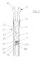
- the head piece 5 is about mushroom-shaped projections 19, which are visible here, because Fig. 2 a compared to Fig. 1 rotated by 90 ° view.
- the head piece 5 with its insertable into the tube sleeve 4 shank portion 6 is an injection molded part made of plastic.
- the shaft portion 6 has a molded spring tongue 20 on. At the free end of the spring tongue 20 is located a snap stop 21, here as a thickening 22 of the spring tongue 20 is formed.
- a recess 23 in the form a simple hole. If the head piece 5 with its shaft portion. 6 inserted into the tube sleeve 4 from above, so first the thickening 22 at the free end of the spring tongue 20, the spring tongue 20 deflect until a Inserted position of the shaft portion is reached, in which the Snap stop 21, or the thickening 22, in the recess 23rd snaps or clicks. As a result, the head piece 5 with the tube sleeve 4th locked.
- the head piece 5 with its shank portion 6 from the tube sleeve 4 again can be removed from the outside through the recess 23 on the Thickening 22, for example, with a suitable tool, so pressed be that the spring tongue 20 is deflected inwardly, whereby the Snap stop 21 out of engagement with the tube sleeve 4 comes.
- anti-rotation elements which is caused by that the head piece 5 with its shank portion 6 relative to the tube sleeve 4th can not be twisted.
- the coil spring 7 can be assembled by attaching to the holding nubs with the consisting of shaft portion 6 and head piece 5 a component form a preassemblable unit. Such units allow a change quickly accomplish the tension springs of a clapper.
Landscapes
- Engineering & Computer Science (AREA)
- Textile Engineering (AREA)
- Braiding, Manufacturing Of Bobbin-Net Or Lace, And Manufacturing Of Nets By Knotting (AREA)
Applications Claiming Priority (2)
| Application Number | Priority Date | Filing Date | Title |
|---|---|---|---|
| DE10343736 | 2003-09-22 | ||
| DE2003143736 DE10343736A1 (de) | 2003-09-22 | 2003-09-22 | Klöppel für eine Flechtmaschine |
Publications (1)
| Publication Number | Publication Date |
|---|---|
| EP1516951A1 true EP1516951A1 (fr) | 2005-03-23 |
Family
ID=34177876
Family Applications (1)
| Application Number | Title | Priority Date | Filing Date |
|---|---|---|---|
| EP04022375A Withdrawn EP1516951A1 (fr) | 2003-09-22 | 2004-09-21 | sytème de blockage à montage rapide pour un ressort de tension du fil |
Country Status (2)
| Country | Link |
|---|---|
| EP (1) | EP1516951A1 (fr) |
| DE (1) | DE10343736A1 (fr) |
Cited By (1)
| Publication number | Priority date | Publication date | Assignee | Title |
|---|---|---|---|---|
| CN106757757A (zh) * | 2016-12-23 | 2017-05-31 | 张百君 | 低噪声弹簧锭子 |
Families Citing this family (1)
| Publication number | Priority date | Publication date | Assignee | Title |
|---|---|---|---|---|
| DE102019101619B4 (de) | 2019-01-23 | 2022-04-07 | ADMEDES GmbH | Klöppel für eine Flechtmaschine, Flechtmaschine und Verfahren zum Erzeugen einer Zugspannung in Flechtmaterial beim Flechten |
Citations (3)
| Publication number | Priority date | Publication date | Assignee | Title |
|---|---|---|---|---|
| GB973584A (en) * | 1962-04-13 | 1964-10-28 | B & F Carter & Co Ltd | Improvements in or relating to brading machine carriers |
| DE1949893A1 (de) * | 1969-10-03 | 1971-04-15 | Herzog Maschf A | Flechtmaschine zur Herstellung knotenlos geflochtener Netzbahnen |
| US5383387A (en) * | 1990-08-17 | 1995-01-24 | United States Surgical Corporation | Apparatus and method for producing braided suture products |
-
2003
- 2003-09-22 DE DE2003143736 patent/DE10343736A1/de not_active Withdrawn
-
2004
- 2004-09-21 EP EP04022375A patent/EP1516951A1/fr not_active Withdrawn
Patent Citations (3)
| Publication number | Priority date | Publication date | Assignee | Title |
|---|---|---|---|---|
| GB973584A (en) * | 1962-04-13 | 1964-10-28 | B & F Carter & Co Ltd | Improvements in or relating to brading machine carriers |
| DE1949893A1 (de) * | 1969-10-03 | 1971-04-15 | Herzog Maschf A | Flechtmaschine zur Herstellung knotenlos geflochtener Netzbahnen |
| US5383387A (en) * | 1990-08-17 | 1995-01-24 | United States Surgical Corporation | Apparatus and method for producing braided suture products |
Cited By (1)
| Publication number | Priority date | Publication date | Assignee | Title |
|---|---|---|---|---|
| CN106757757A (zh) * | 2016-12-23 | 2017-05-31 | 张百君 | 低噪声弹簧锭子 |
Also Published As
| Publication number | Publication date |
|---|---|
| DE10343736A1 (de) | 2005-04-21 |
Similar Documents
| Publication | Publication Date | Title |
|---|---|---|
| DE69222392T2 (de) | Zahnbürste | |
| DE102007040187B3 (de) | Führungshülse für eine Haltestange einer Kopfstütze | |
| DE102015109997B4 (de) | Halterung | |
| WO2011035966A4 (fr) | Soupape anti-retour à deux éléments de fermeture | |
| EP0712802B1 (fr) | Adaptateur de bobine | |
| DE102012015288A1 (de) | Entriegelungseinheit für einen Fahrzeugsitz und Fahrzeugsitz | |
| DE69500715T2 (de) | Montagevorrichtung zur Befestigung des Endteils einer Spiralfeder an einem anderen Element | |
| DE102012220830B4 (de) | Steuerventil für eine hydraulische Vorrichtung mit einer austauschbaren Hydraulikeinheit | |
| DE102018205929A1 (de) | Befestigungsvorrichtung mit einem Basisteil und einem Sperrteil | |
| DE69921069T2 (de) | System zur Verbindung von Ventilanordnungen für Gaswassererhitzer zur Gefässen von diesen Wassererhitzern | |
| EP1516951A1 (fr) | sytème de blockage à montage rapide pour un ressort de tension du fil | |
| EP4012200B1 (fr) | Boulon d'encliquetage sollicité par ressort | |
| DE4235843C2 (de) | Anhängekupplung | |
| WO2003070079A1 (fr) | Balai a franges auto-essorant | |
| DE10109752C1 (de) | Greifelement für Federspanner | |
| DE4213958C1 (en) | Installation for joining harness to jacquard machine - has 1st coupling element which gathers harness cords and is opt. connected to 2nd coupling element associated with jacquard machine | |
| DE19508638C2 (de) | Handbrause | |
| DE102009054054A1 (de) | Montageanordnung und Verfahren zur Montage eines Druckspeichers für Brennkraftmaschinen | |
| EP0937802A2 (fr) | Porte-bobine pour métier à tresser | |
| EP0058391A1 (fr) | Dispositif de fixation sur des pièces de garnissage ou d'installation pouvant être reliées l'une à l'autre de manière amovible et procédé pour la fabrication d'un tel dispositif | |
| CH711810B1 (de) | Vorrichtung zum wieder lösbaren Verbinden einer Zubehörbox mit einer Nähmaschine. | |
| AT412729B (de) | Rotordeckel für eine rotorspinnvorrichtung | |
| DE19912235B4 (de) | Anordnung eines Kabelhakens am Gehäuse eines Staubsaugers | |
| DE60114654T2 (de) | Verbindungsvorrichtung für schnüre | |
| DE202019103311U1 (de) | Vorrichtung zum verriegelten Verbinden mit einem Verbindungszapfen und Anordnung |
Legal Events
| Date | Code | Title | Description |
|---|---|---|---|
| PUAI | Public reference made under article 153(3) epc to a published international application that has entered the european phase |
Free format text: ORIGINAL CODE: 0009012 |
|
| AK | Designated contracting states |
Kind code of ref document: A1 Designated state(s): AT BE BG CH CY CZ DE DK EE ES FI FR GB GR HU IE IT LI LU MC NL PL PT RO SE SI SK TR |
|
| AX | Request for extension of the european patent |
Extension state: AL HR LT LV MK |
|
| AKX | Designation fees paid | ||
| REG | Reference to a national code |
Ref country code: DE Ref legal event code: 8566 |
|
| STAA | Information on the status of an ep patent application or granted ep patent |
Free format text: STATUS: THE APPLICATION IS DEEMED TO BE WITHDRAWN |
|
| 18D | Application deemed to be withdrawn |
Effective date: 20050924 |