EP1516908B1 - Verkokungstrommel mit einem Rohrbrückenschieber - Google Patents
Verkokungstrommel mit einem Rohrbrückenschieber Download PDFInfo
- Publication number
- EP1516908B1 EP1516908B1 EP04022218A EP04022218A EP1516908B1 EP 1516908 B1 EP1516908 B1 EP 1516908B1 EP 04022218 A EP04022218 A EP 04022218A EP 04022218 A EP04022218 A EP 04022218A EP 1516908 B1 EP1516908 B1 EP 1516908B1
- Authority
- EP
- European Patent Office
- Prior art keywords
- pipe
- coke drum
- valve
- coking
- gate valve
- Prior art date
- Legal status (The legal status is an assumption and is not a legal conclusion. Google has not performed a legal analysis and makes no representation as to the accuracy of the status listed.)
- Expired - Lifetime
Links
- 239000000571 coke Substances 0.000 title claims description 37
- 238000004939 coking Methods 0.000 claims abstract description 67
- 238000007789 sealing Methods 0.000 claims abstract description 56
- 238000000034 method Methods 0.000 claims abstract description 24
- 230000008569 process Effects 0.000 claims abstract description 15
- 238000005260 corrosion Methods 0.000 claims abstract description 6
- 230000007797 corrosion Effects 0.000 claims abstract description 6
- 239000000463 material Substances 0.000 claims abstract 2
- 239000002184 metal Substances 0.000 claims abstract 2
- 238000005292 vacuum distillation Methods 0.000 claims description 7
- 239000010779 crude oil Substances 0.000 claims description 6
- 238000007373 indentation Methods 0.000 claims description 5
- 238000004519 manufacturing process Methods 0.000 claims description 3
- 239000002006 petroleum coke Substances 0.000 claims description 3
- 239000011248 coating agent Substances 0.000 claims description 2
- 238000000576 coating method Methods 0.000 claims description 2
- 238000007747 plating Methods 0.000 claims 2
- 230000004308 accommodation Effects 0.000 claims 1
- 230000004913 activation Effects 0.000 claims 1
- 230000008878 coupling Effects 0.000 claims 1
- 238000010168 coupling process Methods 0.000 claims 1
- 238000005859 coupling reaction Methods 0.000 claims 1
- 210000003660 reticulum Anatomy 0.000 claims 1
- 238000011010 flushing procedure Methods 0.000 abstract description 7
- 239000007787 solid Substances 0.000 abstract description 2
- 238000005253 cladding Methods 0.000 abstract 1
- 239000007789 gas Substances 0.000 description 12
- 241000196324 Embryophyta Species 0.000 description 8
- 230000000694 effects Effects 0.000 description 6
- XLYOFNOQVPJJNP-UHFFFAOYSA-N water Substances O XLYOFNOQVPJJNP-UHFFFAOYSA-N 0.000 description 6
- 230000008901 benefit Effects 0.000 description 5
- 150000002430 hydrocarbons Chemical class 0.000 description 4
- 238000010276 construction Methods 0.000 description 3
- 238000005336 cracking Methods 0.000 description 3
- 229930195733 hydrocarbon Natural products 0.000 description 3
- 238000012423 maintenance Methods 0.000 description 3
- 238000004227 thermal cracking Methods 0.000 description 3
- 239000004215 Carbon black (E152) Substances 0.000 description 2
- 208000027418 Wounds and injury Diseases 0.000 description 2
- 230000009471 action Effects 0.000 description 2
- 238000004523 catalytic cracking Methods 0.000 description 2
- 238000004140 cleaning Methods 0.000 description 2
- 239000002826 coolant Substances 0.000 description 2
- 238000001816 cooling Methods 0.000 description 2
- 238000005520 cutting process Methods 0.000 description 2
- 230000006378 damage Effects 0.000 description 2
- 230000003111 delayed effect Effects 0.000 description 2
- 230000001419 dependent effect Effects 0.000 description 2
- 238000013461 design Methods 0.000 description 2
- 239000000428 dust Substances 0.000 description 2
- 230000006872 improvement Effects 0.000 description 2
- 208000014674 injury Diseases 0.000 description 2
- 230000007246 mechanism Effects 0.000 description 2
- 239000003921 oil Substances 0.000 description 2
- 239000002245 particle Substances 0.000 description 2
- 238000012545 processing Methods 0.000 description 2
- OKTJSMMVPCPJKN-UHFFFAOYSA-N Carbon Chemical compound [C] OKTJSMMVPCPJKN-UHFFFAOYSA-N 0.000 description 1
- 240000006829 Ficus sundaica Species 0.000 description 1
- 230000001464 adherent effect Effects 0.000 description 1
- XAGFODPZIPBFFR-UHFFFAOYSA-N aluminium Chemical compound [Al] XAGFODPZIPBFFR-UHFFFAOYSA-N 0.000 description 1
- 229910052782 aluminium Inorganic materials 0.000 description 1
- 238000001354 calcination Methods 0.000 description 1
- 229910052799 carbon Inorganic materials 0.000 description 1
- 230000003197 catalytic effect Effects 0.000 description 1
- 238000004517 catalytic hydrocracking Methods 0.000 description 1
- 238000006243 chemical reaction Methods 0.000 description 1
- 239000000356 contaminant Substances 0.000 description 1
- 238000011161 development Methods 0.000 description 1
- 230000018109 developmental process Effects 0.000 description 1
- 239000002283 diesel fuel Substances 0.000 description 1
- 239000010771 distillate fuel oil Substances 0.000 description 1
- 238000004821 distillation Methods 0.000 description 1
- 238000011049 filling Methods 0.000 description 1
- 239000012530 fluid Substances 0.000 description 1
- 238000005194 fractionation Methods 0.000 description 1
- 239000003502 gasoline Substances 0.000 description 1
- 239000011491 glass wool Substances 0.000 description 1
- 239000002010 green coke Substances 0.000 description 1
- 239000010763 heavy fuel oil Substances 0.000 description 1
- 238000007689 inspection Methods 0.000 description 1
- 239000011810 insulating material Substances 0.000 description 1
- 239000007788 liquid Substances 0.000 description 1
- 238000010327 methods by industry Methods 0.000 description 1
- 239000011490 mineral wool Substances 0.000 description 1
- 230000035515 penetration Effects 0.000 description 1
- 238000003825 pressing Methods 0.000 description 1
- 230000002035 prolonged effect Effects 0.000 description 1
- 238000010926 purge Methods 0.000 description 1
- 238000003892 spreading Methods 0.000 description 1
- 230000007480 spreading Effects 0.000 description 1
- 239000002341 toxic gas Substances 0.000 description 1
- 238000009966 trimming Methods 0.000 description 1
Images



Classifications
-
- C—CHEMISTRY; METALLURGY
- C10—PETROLEUM, GAS OR COKE INDUSTRIES; TECHNICAL GASES CONTAINING CARBON MONOXIDE; FUELS; LUBRICANTS; PEAT
- C10B—DESTRUCTIVE DISTILLATION OF CARBONACEOUS MATERIALS FOR PRODUCTION OF GAS, COKE, TAR, OR SIMILAR MATERIALS
- C10B1/00—Retorts
- C10B1/02—Stationary retorts
- C10B1/04—Vertical retorts
-
- C—CHEMISTRY; METALLURGY
- C10—PETROLEUM, GAS OR COKE INDUSTRIES; TECHNICAL GASES CONTAINING CARBON MONOXIDE; FUELS; LUBRICANTS; PEAT
- C10B—DESTRUCTIVE DISTILLATION OF CARBONACEOUS MATERIALS FOR PRODUCTION OF GAS, COKE, TAR, OR SIMILAR MATERIALS
- C10B25/00—Doors or closures for coke ovens
- C10B25/02—Doors; Door frames
- C10B25/08—Closing and opening the doors
- C10B25/10—Closing and opening the doors for ovens with vertical chambers
Definitions
- the present invention relates to a coking drum according to the preamble of claim 1 and a coking process, which serves in particular for the coking of residues from the vacuum distillation of crude oil, according to the preamble of claim 13.
- thermal cracking The longest known and probably simplest cracking process is thermal cracking. Hydrocarbon chains are split at high temperatures.
- the group of thermal cracking processes include the so-called visbreaking and coking, in which carbon settles in solid form, so-called coke or petroleum coke.
- the feedstock e.g. the residue may be from vacuum distillation, passed into an oven and heated to about 500 ° C. Because of these conditions, it flows through the furnace at very high speed and then coked when entering a separate from the furnace and connected thereto via a pipe coking or coking drum, in which a chamber pressure of about 4 bar prevails.
- each furnace is associated with at least two coking drums, one of which is in operation while the other of the coke is being removed. This can e.g. be cut out of the coking drum by means of water under high pressure.
- the resulting from coking light hydrocarbons are passed from the coking chamber in a disproportionateierturm and further processed there.
- the resulting petroleum coke is called green coke and can either be sold after crushing or further refined.
- the refinement takes place in a calcination process in which at temperatures of 1200 ° C and more remaining oil components are burned and coked.
- the resulting calcinate can then be used, for example, for electrodes that are used in the aluminum industry.
- Each filled drum is cooled and the coke is removed from it.
- water is first fed into the drum to cool the resulting, hot coke.
- the drum is opened to the atmosphere by, depending on the type of coking chamber or drum, either only the bottom side or the head side of the drum or chamber is opened, so that the coke cut out of the drum and its further use can be supplied.
- the process of opening the coking drum may have hazards for several reasons.
- the water that is introduced into the drum for cooling the coke before opening the drum becomes very hot, which, if the apparatus is not handled carefully, can lead to injuries due to escaping hot water or steam which is under pressure.
- loose pieces of coke may fall out of the drum or load the opening mechanisms so that they open abruptly after unlocking, which can also lead to injury to the operator.
- the operator may also be exposed to dusts, especially coke particles and also irritating or toxic gases when the drums are opened.
- Disadvantage of the above-mentioned device is moderate security against accidental leakage of hot water or vapors and gases from the coking drum. Furthermore, due to the design, it can lead to disturbances, since coke or the like bakes on the guide rails of the slide, in particular on the side of the guide rails facing the coking chamber.
- Object of the present invention is therefore to provide a coking drum, the shutter works functionally and interference-proof.
- An essential point of the invention is therefore that at an outlet and / or at or near an inlet and / or at an access opening of the coking drum, a pipe bridge slider is arranged as Absperrglied having two shut-off plates. This makes it possible to seal the coking chamber with increased safety.
- a departure from the known closures with screwing completed on the other hand, an improvement over the already known slide closures in two respects made an improvement: on the one hand a double plate slide is provided in this form for the first time, the second part of the idea of the pipe bridge slider for the present invention.
- the two shut-off plates are assigned to each other parallel, fully metallic sealing seats. These are characterized by an excellent sealing effect.
- sealing seat surfaces assigned to the sealing seats have wear-resistant and corrosion-resistant hard armor. This minimizes abrasive wear on the seal seating surfaces, extends service intervals, and allows cost savings.
- the two shut-off plates are preferably inserted movably into a spectacle-shaped plate cage, which makes the maintenance of the device according to the invention even simpler.
- a pipe bridge that connects two pipe sockets in an open position of the pipe bridge slide, which are attached to the interior of the coking drum side facing and this opposite side of the pipe bridge slide, hollow cylindrical, in particular circular cylindrical.
- the pipe bridge has a smooth surface with the lowest possible roughness, thereby minimizing flow losses.
- the pipe bridge on its inside a wear and corrosion resistant hard armor or coating, or is cured there. As a result, the abrasive wear on the pipe bridge is kept as low as possible.
- the shut-off plates are pressed in the closed position by means of a ball-centered wedge pieces on sealing surfaces.
- This solution is also characterized by its low susceptibility to interference. Caking of coke or the like on the guide rails of the shut-off plates is avoided by pressing them into the sealing position.
- a slide associated with the shut-off plates is equipped with guide plates which constantly have metallic contact with the plate cage. This promotes the sealing effect and reduces abrasive wear.
- an actuating rod associated with the shut-off plates is introduced in a fluid-tight manner into the slide housing, wherein a connection is provided on the slide housing for connection to a compressed gas source, in particular for connection to a flushing or sealing steam source.
- a connection is provided on the slide housing for connection to a compressed gas source, in particular for connection to a flushing or sealing steam source.
- the pipe bridge valve of the coking chamber according to the invention additionally has a compensator unit which offers the advantage that small gaps or misregistrations in the pass can be compensated in a simple manner
- the compressed gas connection offers further advantages.
- the sealing effect of the pipe bridge slide can be additionally reinforced in the open position of the slide.
- flushing steam offers a cost saving potential, since this is needed to clean the housing interior and the guide plates and the plate cage.
- the flushing steam thus serves on the one hand to improve the sealing effect, on the other hand at the same time the cleaning of the closure device of the coking drum according to the invention.
- hoods with a pillar attachment for mounting the drive are flanged to the slide housing.
- This embodiment is characterized by a particularly simple construction.
- the pipe bridge slider as already mentioned above, a Kompensatorü.
- the Kompensatorü offers the advantage that small gaps or Prudaumaschineen can be compensated in a simple manner, resulting in an excellent sealing function in every situation.
- the compensator comprises in a preferred embodiment, a wavy curved pipe section having a recess extending over the circumference, wherein the wavy curved pipe section as an outer pipe section extends coaxially over an inner pipe section which is firmly connected to one of the two sealing rings, while he opposite the other sealing ring is axially movable.
- a wavy curved pipe section having a recess extending over the circumference, wherein the wavy curved pipe section as an outer pipe section extends coaxially over an inner pipe section which is firmly connected to one of the two sealing rings, while he opposite the other sealing ring is axially movable.
- the pressure prevailing in the interior of the drum when opening the coking drum is used to press the shut-off plate facing the interior of the drum out of its associated sealing seat. This reduces the force required to open a coking drum or its shut-off.
- Fig. 1 is a schematic representation of a coking plant. This consists of: a furnace 1, which is fed via a line 2 with the residues from the vacuum distillation of crude oil; two coking chambers 3, 4, which are fed via a line 5 with the oven-heated residues from the vacuum distillation; a conveyor belt 6, with which the coke produced in the coking chambers is transported further; and a fractionating column 7, in which the resulting in the coking process in the coking chambers 3 and 4 gases which are fed to the fractionation column 7 via a line 8, are fractionated.
- the coking plant has an oven 9 with a turntable, in which at least parts of the coke obtained in the coking chamber are calcined.
- the heavy residues remaining in the fractionating column 7 are returned via an outlet 12 and a line 10 in the line 2 and thus again fed to the coking process.
- the coking chambers 3, 4 can be openable on only one side for the removal of coke accumulated therein, as well as on two sides, ie on a head and a foot end, so as to ensure a facilitated removal , For this purpose, a shut-off 11 and the coke is then removed using suitable equipment.
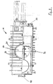
- FIG. 2 . 3 and 4 is a first embodiment of the obturator 11 for the coking chambers 3, 4 shown in different views. Additionally is in Fig. 5 a detailed view of the in Fig. 2 given with Y marked area.
- the slide shown has a slide housing 21 with two pipe sockets 22 and 23 and two Gepurichtsitze 24 and 25, between which two shut-off plates 27, 28 with sealing rings 29, 30 are slidably mounted.
- the two shut-off plates 27 and 28 can be pressed against the housing sealing seats 24 and 25 with the aid of an internal wedge 31 acting as a spreading member, which is seated at the end of an actuating rod 32 and firmly connected thereto.
- the shut-off plates 27, 28 are for this purpose by the inner wedge 31, which is centered by means of a ball, according to a "wedge-in-wedge principle" spreadable. This design ensures that the slider is easy to operate even under the most severe thermal and dynamic conditions. Jamming is not possible because the inner wedge 31 has a non-self-locking shape.
- a pipe bridge 33 which has two sealing rings 34, 35.
- the pipe bridge 33 is formed as a hollow cylinder, that is, it has in particular in its inner side no corrugations, so that no consequent flow losses form (see also Fig. 4 ).
- the slider is shown in the closed position.
- the slider housing 21 is formed fluid-tight to the outside, so that in the interior 43 of the valve body, a gas pressure is adjustable, which may also be greater than the pressure in the slide passage. For this reason, the operating rod 32 is fluid-tightly inserted into the slider housing 21.
- a continuous flushing of the interior 43 of the valve body By a continuous flushing of the interior 43 of the valve body, the caking of dirt and a resulting disturbance of the coking chambers 3.4 is largely avoided.
- the sealing surfaces of the sealing rings 34, 35 on the one hand and the housing sealing seats 24, 25 on the other are each formed extending parallel to the slide actuating direction. To increase the wear resistance, the aforementioned are hardened or armored in a conventional manner.
- shut-off plates 27, 28 are inserted in a spectacle-shaped plate cage (not shown in the figures), which ensures their holder, movable. This plate cage is guided between guide plates 45, which prevents the penetration of contaminants into the housing.
- the actuating rod 32 Via a coolant inlet 51, the actuating rod 32, in particular at its protruding from the housing end, to be cooled. This is preferably done by cold air or cold gases. At this point it should be mentioned that a liquid cooling is conceivable.
- Fig. 4 is the obturator 11 in its open position along a section line XX of Fig. 2 shown.
- the pipe bridge 33 connects the pipe socket 22, 23 without tapering the cross section.
- Fig. 5 The in Fig. 2 with Y marked cutout is in Fig. 5 again shown in magnification.
- a rinsing and sealing steam channel 53 which at a connecting piece 52 (s. Fig. 3 ) is connected to a rinsing and sealing vapor source.
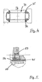
- FIGS. 6 and 7 a second embodiment of the shut-off member 11 of the coking chamber 3, 4 is shown. Identical parts or parts with the same functionality have the same reference numerals as the obturator according to the first Embodiment ( Fig. 2 to Fig. 5 ). They will therefore not be described further below.
- the pipe bridge 33 of the shut-off member 11 is composed of the sealing rings 34 and 35 and a joint 36 connecting the sealing rings together.
- the compensator 36 consists of an inner tube section 37 and a coaxially extending outer tube section 38, wherein the outer tube section 38 via ring welds 39, 40 with two sealing rings 34, 35 is firmly connected.
- the outer tube section 38 has a shaft or indentation 41 extending over the circumference.
- the inner tube section 37 is hollow cylindrical, i. formed without a shaft, so that analogous to the shut-off member 11 according to the first embodiment, no trimming losses can occur.
- the inner tube section 37 is axially movable, wherein the axial clearance between the sealing ring 34 and the inner tube section 37 is between about 1.0 mm to about 5.0 mm.
- the arrangement of the inner tube section 36 relative to the two sealing rings 34 and 35 is such that the inner surface of the tube section 36 with the inner surfaces of the sealing rings 34, 35 are aligned, so that a virtually continuous flow passage is provided in the open position of the slider.
- the slider is analogous to the Figures 2 and 3 each shown in the closed position.
- the slider housing 21 is formed fluid-tight to the outside, so that within the slider housing analogous to the first embodiment, a gas pressure is adjustable.
- the circumferential indentation 41 of the outer tube section 38 extends to close to the outer surface of the inner tube section 37, so that the prevailing in the housing 43 gas pressure on the indentation 41 on the sealing rings 34, 35 under axial spread of the same is fully effective.
- the axial spread of the sealing rings 34, 35 is on the one hand by the indentation 41 and the other by the Axial play between the inner pipe section 37 and one of the two sealing rings, here sealing ring 34, possible.
- the pipe bridge 33 is accordingly limited by the two sealing rings 34, 35 on the one hand and the inner and outer pipe sections 37, 38 serving as compensator 36, which are arranged between them, on the other hand, forming a ring box 46.
- This ring box 46 and the annular space between the inner and outer tube section 37 and 38 is filled with a heat-insulating material, in particular glass wool, rock wool or the like.
- the filling has not only a heat-insulating purpose, but also the purpose to prevent the ingress of flow medium in said annular space between the inner and outer pipe section. Clogging of the annulus with flow medium or gas flow with dust and dirt particles or similar deposits would interfere with or impair the action of the compensator 36 after prolonged use.
- the aforementioned embodiment has a double function.
- the respectively filled coking drum 3, 4, however, is cooled, and the coke is removed from it.
- water is first passed into the coking drum 3, 4 in order to cool the resulting, hot coke.
- the coking drum 3, 4 is opened to the atmosphere, wherein the pressure prevailing in the interior of the coking drum 3, 4 pressure pushes the shut-off plate facing the interior of the valve seat and thus necessary for opening the pipe bridge slide Reduced effort.
Landscapes
- Chemical & Material Sciences (AREA)
- Engineering & Computer Science (AREA)
- Oil, Petroleum & Natural Gas (AREA)
- Materials Engineering (AREA)
- Organic Chemistry (AREA)
- Coke Industry (AREA)
- Sliding Valves (AREA)
- Fluid-Driven Valves (AREA)
- Taps Or Cocks (AREA)
- Valve Housings (AREA)
- Preparation Of Clay, And Manufacture Of Mixtures Containing Clay Or Cement (AREA)
Priority Applications (1)
| Application Number | Priority Date | Filing Date | Title |
|---|---|---|---|
| PL04022218T PL1516908T3 (pl) | 2003-09-18 | 2004-09-17 | Bęben koksowniczy z rurową zasuwą |
Applications Claiming Priority (2)
| Application Number | Priority Date | Filing Date | Title |
|---|---|---|---|
| DE10343298A DE10343298A1 (de) | 2003-09-18 | 2003-09-18 | Verkokungstrommel |
| DE10343298 | 2003-09-18 |
Publications (2)
| Publication Number | Publication Date |
|---|---|
| EP1516908A1 EP1516908A1 (de) | 2005-03-23 |
| EP1516908B1 true EP1516908B1 (de) | 2008-12-24 |
Family
ID=34177823
Family Applications (1)
| Application Number | Title | Priority Date | Filing Date |
|---|---|---|---|
| EP04022218A Expired - Lifetime EP1516908B1 (de) | 2003-09-18 | 2004-09-17 | Verkokungstrommel mit einem Rohrbrückenschieber |
Country Status (6)
| Country | Link |
|---|---|
| US (2) | US20050133358A1 (pl) |
| EP (1) | EP1516908B1 (pl) |
| AT (1) | ATE418592T1 (pl) |
| DE (2) | DE10343298A1 (pl) |
| ES (1) | ES2320339T3 (pl) |
| PL (1) | PL1516908T3 (pl) |
Cited By (2)
| Publication number | Priority date | Publication date | Assignee | Title |
|---|---|---|---|---|
| DE102012101015A1 (de) | 2012-02-08 | 2013-08-08 | Z & J Technologies Gmbh | Verkokungstrommel, Absperrventil für eine Verkokungstrommel und Verfahren zum Zuführen von Reststoffen in eine Verkokungstrommel |
| DE102018116738A1 (de) | 2018-07-11 | 2020-01-16 | Z & J Technologies Gmbh | Befüllvorrichtung, Verkokungstrommel, System zur Rohölverarbeitung, Verfahren zum Herstellen von Petroleumkoks |
Families Citing this family (12)
| Publication number | Priority date | Publication date | Assignee | Title |
|---|---|---|---|---|
| US8282074B2 (en) * | 2001-03-12 | 2012-10-09 | Curtiss-Wright Flow Control Corporation | Delayed coker isolation valve systems |
| US7316762B2 (en) | 2003-04-11 | 2008-01-08 | Curtiss-Wright Flow Control Corporation | Dynamic flange seal and sealing system |
| US7117959B2 (en) * | 2004-04-22 | 2006-10-10 | Curtiss-Wright Flow Control Corporation | Systems and methods for remotely determining and changing cutting modes during decoking |
| US7473337B2 (en) * | 2004-04-22 | 2009-01-06 | Curtiss-Wright Flow Control Corporation | Remotely controlled decoking tool used in coke cutting operations |
| US7931044B2 (en) * | 2006-03-09 | 2011-04-26 | Curtiss-Wright Flow Control Corporation | Valve body and condensate holding tank flushing systems and methods |
| CN102392900B (zh) * | 2011-11-09 | 2013-02-06 | 冈野集团有限公司 | 一种平板闸阀 |
| CN102678954A (zh) * | 2012-05-17 | 2012-09-19 | 东莞宏威数码机械有限公司 | 单面密封双向承压真空闸阀装置 |
| CN102678955A (zh) * | 2012-05-17 | 2012-09-19 | 东莞宏威数码机械有限公司 | 双挡板真空闸阀装置 |
| US9334447B2 (en) * | 2012-10-19 | 2016-05-10 | Deltavalve, Llc | Flushing system for use in delayed coking systems |
| CN105822782B (zh) * | 2015-01-07 | 2018-07-27 | 新莱应材科技有限公司 | 连杆闸板阀 |
| CN108757973B (zh) * | 2018-08-16 | 2023-11-14 | 北京航天石化技术装备工程有限公司 | 一种双闸板闸阀 |
| CN116792521B (zh) * | 2023-07-05 | 2025-07-29 | 四川九天真空科技有限公司 | 一种具有双向密封功能的矩形阀 |
Family Cites Families (20)
| Publication number | Priority date | Publication date | Assignee | Title |
|---|---|---|---|---|
| US1482677A (en) * | 1922-10-04 | 1924-02-05 | Charles J Dunten | Shale retort |
| US1709815A (en) * | 1928-03-20 | 1929-04-16 | Ionizing Corp Of America | Apparatus and method for dissociating hydrocarbon fluids and solids for production of gases and liquids of lighter molecular weight |
| US2283556A (en) * | 1933-12-11 | 1942-05-19 | Lewis C Karrick | Valve |
| US2310748A (en) * | 1940-04-01 | 1943-02-09 | Paul W Pearson | Process and apparatus for removing coke from stills |
| US2317566A (en) * | 1941-07-24 | 1943-04-27 | Socony Vacuum Oil Co Inc | Apparatus for coking oils |
| US2778781A (en) * | 1953-05-25 | 1957-01-22 | Jenkins Petroleum Process Comp | Process for the continuous coking of hydrocarbons |
| FR2054522B1 (pl) | 1969-07-30 | 1973-05-11 | Guichon Robert | |
| SU1518349A1 (ru) | 1987-01-15 | 1989-10-30 | Уфимский Филиал Всесоюзного Научно-Исследовательского И Проектно-Конструкторского Института Нефтяного Машиностроения | Затвор реакционной камеры |
| DE4011274C1 (pl) * | 1990-04-06 | 1991-08-01 | Zimmermann & Jansen Gmbh, 5160 Dueren, De | |
| DE4405836A1 (de) * | 1994-02-23 | 1995-08-24 | Zimmermann & Jansen Gmbh | Schieber zum Absperren großer Fluidleitungen, insbesondere Doppelplattenschieber |
| US5417811A (en) * | 1994-06-13 | 1995-05-23 | Foster Wheeler Usa Corporation | Closure device for upper head of coking drums |
| US5565714A (en) * | 1995-06-06 | 1996-10-15 | Cunningham; John C. | Power conservation circuit |
| DE29623103U1 (de) * | 1996-10-23 | 1997-11-06 | Zimmermann & Jansen GmbH, 52355 Düren | Schieber, insbesondere Rohrbrückenschieber |
| EP2045310B1 (en) * | 2001-03-12 | 2014-07-09 | Curtiss-Wright Flow Control Corporation | Improved coke drum de-heading system |
| US6964727B2 (en) * | 2001-03-12 | 2005-11-15 | Curtiss-Wright Flow Control Corporation | Coke drum bottom de-heading system |
| US8512525B2 (en) * | 2001-03-12 | 2013-08-20 | Curtiss-Wright Flow Control Corporation | Valve system and method for unheading a coke drum |
| US7247220B2 (en) * | 2001-11-09 | 2007-07-24 | Foster Wheeler Usa Corporation | Coke drum discharge system |
| US6843889B2 (en) * | 2002-09-05 | 2005-01-18 | Curtiss-Wright Flow Control Corporation | Coke drum bottom throttling valve and system |
| US7037408B2 (en) * | 2002-12-18 | 2006-05-02 | Chevron U.S.A. Inc. | Safe and automatic method for preparation of coke for removal from a coke vessel |
| US7316762B2 (en) * | 2003-04-11 | 2008-01-08 | Curtiss-Wright Flow Control Corporation | Dynamic flange seal and sealing system |
-
2003
- 2003-09-18 DE DE10343298A patent/DE10343298A1/de not_active Ceased
-
2004
- 2004-09-16 US US10/942,308 patent/US20050133358A1/en not_active Abandoned
- 2004-09-17 ES ES04022218T patent/ES2320339T3/es not_active Expired - Lifetime
- 2004-09-17 PL PL04022218T patent/PL1516908T3/pl unknown
- 2004-09-17 EP EP04022218A patent/EP1516908B1/de not_active Expired - Lifetime
- 2004-09-17 AT AT04022218T patent/ATE418592T1/de active
- 2004-09-17 DE DE502004008728T patent/DE502004008728D1/de not_active Expired - Lifetime
-
2007
- 2007-01-18 US US11/624,569 patent/US7666280B2/en not_active Expired - Lifetime
Cited By (5)
| Publication number | Priority date | Publication date | Assignee | Title |
|---|---|---|---|---|
| DE102012101015A1 (de) | 2012-02-08 | 2013-08-08 | Z & J Technologies Gmbh | Verkokungstrommel, Absperrventil für eine Verkokungstrommel und Verfahren zum Zuführen von Reststoffen in eine Verkokungstrommel |
| EP2626403A1 (de) | 2012-02-08 | 2013-08-14 | Z & J Technologies GmbH | Verkokungstrommel, Absperrventil für eine Verkokungstrommel und Verfahren zum Zuführen von Reststoffen in eine Verkokungstrommel |
| DE102012101015B4 (de) * | 2012-02-08 | 2013-09-05 | Z & J Technologies Gmbh | Verkokungstrommel, Absperrventil für eine Verkokungstrommel und Verfahren zum Zuführen von Reststoffen in eine Verkokungstrommel |
| US9109706B2 (en) | 2012-02-08 | 2015-08-18 | Z & J Technologies Gmbh | Coking drum |
| DE102018116738A1 (de) | 2018-07-11 | 2020-01-16 | Z & J Technologies Gmbh | Befüllvorrichtung, Verkokungstrommel, System zur Rohölverarbeitung, Verfahren zum Herstellen von Petroleumkoks |
Also Published As
| Publication number | Publication date |
|---|---|
| ES2320339T3 (es) | 2009-05-21 |
| US20050133358A1 (en) | 2005-06-23 |
| EP1516908A1 (de) | 2005-03-23 |
| DE502004008728D1 (de) | 2009-02-05 |
| ATE418592T1 (de) | 2009-01-15 |
| DE10343298A1 (de) | 2005-04-14 |
| US20080047873A1 (en) | 2008-02-28 |
| PL1516908T3 (pl) | 2009-06-30 |
| US7666280B2 (en) | 2010-02-23 |
Similar Documents
| Publication | Publication Date | Title |
|---|---|---|
| EP1516908B1 (de) | Verkokungstrommel mit einem Rohrbrückenschieber | |
| DE4092044C2 (de) | Vorrichtung zum Verbinden von Rohren und Behältern sowie deren Verwendung | |
| EP1561980B1 (de) | Doppelplattenschieber | |
| DE102007044181A1 (de) | Füllteleskop zum Befüllen von Koksöfen | |
| DE102014112220A1 (de) | Absperrvorrichtung und Plattenschieber mit einer Absperrvorrichtung | |
| DE112010004638T5 (de) | Fernbediente Modus-Schaltvorrichtung für ein kombiniertes Flüssigkeitsstrahl-Entkokungs-Werkzeug und ein Werkzeug mit derselben | |
| EP2626403B1 (de) | Verkokungstrommel, rohrbrückenschieber für eine verkokungstrommel und verfahren zum zuführen von reststoffen in eine verkokungstrommel | |
| EP0727268A2 (de) | Schiebeverschluss für einen Metallschmelze enthaltenden Behälter | |
| EP0819488A2 (de) | Schiebeverschluss für einen Metallschmelze enthaltenden Behälter | |
| CH661341A5 (de) | Drehrohrofen. | |
| DE3424063A1 (de) | Guillotineschieber | |
| EP3707450B1 (de) | Absperrschieber | |
| EP2516086B1 (de) | Schiebeverschluss für einen metallurgischen behälter | |
| DE102006058285B4 (de) | Druckkammer und Verfahren zu deren optischer Überwachung | |
| DE102016107175B4 (de) | Absperrorgan für eine Ethylenherstellungsanlage | |
| DE102020111695B3 (de) | Schieberverschluss mit innenliegendem Dichtkörper und Verfahren zu dessen Montage | |
| DE10296367B3 (de) | Entdeckelungssystem und Entdeckelungsventil sowie Verfahren zum Entdeckeln einer Kokstrommel | |
| DE8400339U1 (de) | Gasdichter Absperrschieber für Schüttgüter, insbesondere Kohle | |
| WO1999060293A1 (de) | Einspritzvorrichtung | |
| DE4414659A1 (de) | Abdichtung zwischen parallelen Stützflächen an zwei Bauteilen | |
| DE202025101692U1 (de) | Plattenschieber | |
| DE4110186C2 (pl) | ||
| DE102022105939A1 (de) | Plattenschieber, Betriebsverfahren und Verwendung | |
| DE102004041462B4 (de) | Verschluss für Druckbehälter | |
| DE202005017073U1 (de) | Hydraulikstempel für Ausbauschilde und Manschettenhalter für diese Hydraulikstempel |
Legal Events
| Date | Code | Title | Description |
|---|---|---|---|
| PUAI | Public reference made under article 153(3) epc to a published international application that has entered the european phase |
Free format text: ORIGINAL CODE: 0009012 |
|
| AK | Designated contracting states |
Kind code of ref document: A1 Designated state(s): AT BE BG CH CY CZ DE DK EE ES FI FR GB GR HU IE IT LI LU MC NL PL PT RO SE SI SK TR |
|
| AX | Request for extension of the european patent |
Extension state: AL HR LT LV MK |
|
| 17P | Request for examination filed |
Effective date: 20050603 |
|
| AKX | Designation fees paid |
Designated state(s): DE FR IT |
|
| RBV | Designated contracting states (corrected) |
Designated state(s): AT BE BG CH CY CZ DE DK EE ES FI FR GB GR HU IE IT LI LU MC NL PL PT RO SE SI SK TR |
|
| GRAP | Despatch of communication of intention to grant a patent |
Free format text: ORIGINAL CODE: EPIDOSNIGR1 |
|
| GRAS | Grant fee paid |
Free format text: ORIGINAL CODE: EPIDOSNIGR3 |
|
| GRAA | (expected) grant |
Free format text: ORIGINAL CODE: 0009210 |
|
| AK | Designated contracting states |
Kind code of ref document: B1 Designated state(s): AT BE BG CH CY CZ DE DK EE ES FI FR GB GR HU IE IT LI LU MC NL PL PT RO SE SI SK TR |
|
| REG | Reference to a national code |
Ref country code: GB Ref legal event code: FG4D Free format text: NOT ENGLISH |
|
| REG | Reference to a national code |
Ref country code: CH Ref legal event code: EP |
|
| REG | Reference to a national code |
Ref country code: IE Ref legal event code: FG4D Free format text: LANGUAGE OF EP DOCUMENT: GERMAN |
|
| REF | Corresponds to: |
Ref document number: 502004008728 Country of ref document: DE Date of ref document: 20090205 Kind code of ref document: P |
|
| REG | Reference to a national code |
Ref country code: RO Ref legal event code: EPE |
|
| REG | Reference to a national code |
Ref country code: ES Ref legal event code: FG2A Ref document number: 2320339 Country of ref document: ES Kind code of ref document: T3 |
|
| PG25 | Lapsed in a contracting state [announced via postgrant information from national office to epo] |
Ref country code: SI Free format text: LAPSE BECAUSE OF FAILURE TO SUBMIT A TRANSLATION OF THE DESCRIPTION OR TO PAY THE FEE WITHIN THE PRESCRIBED TIME-LIMIT Effective date: 20081224 Ref country code: NL Free format text: LAPSE BECAUSE OF FAILURE TO SUBMIT A TRANSLATION OF THE DESCRIPTION OR TO PAY THE FEE WITHIN THE PRESCRIBED TIME-LIMIT Effective date: 20081224 Ref country code: FI Free format text: LAPSE BECAUSE OF FAILURE TO SUBMIT A TRANSLATION OF THE DESCRIPTION OR TO PAY THE FEE WITHIN THE PRESCRIBED TIME-LIMIT Effective date: 20081224 |
|
| NLV1 | Nl: lapsed or annulled due to failure to fulfill the requirements of art. 29p and 29m of the patents act | ||
| REG | Reference to a national code |
Ref country code: PL Ref legal event code: T3 |
|
| REG | Reference to a national code |
Ref country code: IE Ref legal event code: FD4D |
|
| PG25 | Lapsed in a contracting state [announced via postgrant information from national office to epo] |
Ref country code: IE Free format text: LAPSE BECAUSE OF FAILURE TO SUBMIT A TRANSLATION OF THE DESCRIPTION OR TO PAY THE FEE WITHIN THE PRESCRIBED TIME-LIMIT Effective date: 20081224 Ref country code: BG Free format text: LAPSE BECAUSE OF FAILURE TO SUBMIT A TRANSLATION OF THE DESCRIPTION OR TO PAY THE FEE WITHIN THE PRESCRIBED TIME-LIMIT Effective date: 20090324 Ref country code: EE Free format text: LAPSE BECAUSE OF FAILURE TO SUBMIT A TRANSLATION OF THE DESCRIPTION OR TO PAY THE FEE WITHIN THE PRESCRIBED TIME-LIMIT Effective date: 20081224 |
|
| PG25 | Lapsed in a contracting state [announced via postgrant information from national office to epo] |
Ref country code: SE Free format text: LAPSE BECAUSE OF FAILURE TO SUBMIT A TRANSLATION OF THE DESCRIPTION OR TO PAY THE FEE WITHIN THE PRESCRIBED TIME-LIMIT Effective date: 20090324 Ref country code: CZ Free format text: LAPSE BECAUSE OF FAILURE TO SUBMIT A TRANSLATION OF THE DESCRIPTION OR TO PAY THE FEE WITHIN THE PRESCRIBED TIME-LIMIT Effective date: 20081224 Ref country code: PT Free format text: LAPSE BECAUSE OF FAILURE TO SUBMIT A TRANSLATION OF THE DESCRIPTION OR TO PAY THE FEE WITHIN THE PRESCRIBED TIME-LIMIT Effective date: 20090525 |
|
| PG25 | Lapsed in a contracting state [announced via postgrant information from national office to epo] |
Ref country code: SK Free format text: LAPSE BECAUSE OF FAILURE TO SUBMIT A TRANSLATION OF THE DESCRIPTION OR TO PAY THE FEE WITHIN THE PRESCRIBED TIME-LIMIT Effective date: 20081224 |
|
| PG25 | Lapsed in a contracting state [announced via postgrant information from national office to epo] |
Ref country code: DK Free format text: LAPSE BECAUSE OF FAILURE TO SUBMIT A TRANSLATION OF THE DESCRIPTION OR TO PAY THE FEE WITHIN THE PRESCRIBED TIME-LIMIT Effective date: 20081224 |
|
| PLBE | No opposition filed within time limit |
Free format text: ORIGINAL CODE: 0009261 |
|
| STAA | Information on the status of an ep patent application or granted ep patent |
Free format text: STATUS: NO OPPOSITION FILED WITHIN TIME LIMIT |
|
| 26N | No opposition filed |
Effective date: 20090925 |
|
| BERE | Be: lapsed |
Owner name: Z&J TECHNOLOGIES G.M.B.H. Effective date: 20090930 |
|
| PG25 | Lapsed in a contracting state [announced via postgrant information from national office to epo] |
Ref country code: MC Free format text: LAPSE BECAUSE OF NON-PAYMENT OF DUE FEES Effective date: 20090930 |
|
| REG | Reference to a national code |
Ref country code: CH Ref legal event code: PL |
|
| GBPC | Gb: european patent ceased through non-payment of renewal fee |
Effective date: 20090917 |
|
| PG25 | Lapsed in a contracting state [announced via postgrant information from national office to epo] |
Ref country code: BE Free format text: LAPSE BECAUSE OF NON-PAYMENT OF DUE FEES Effective date: 20090930 |
|
| PG25 | Lapsed in a contracting state [announced via postgrant information from national office to epo] |
Ref country code: GR Free format text: LAPSE BECAUSE OF FAILURE TO SUBMIT A TRANSLATION OF THE DESCRIPTION OR TO PAY THE FEE WITHIN THE PRESCRIBED TIME-LIMIT Effective date: 20090325 Ref country code: LI Free format text: LAPSE BECAUSE OF NON-PAYMENT OF DUE FEES Effective date: 20090930 Ref country code: CH Free format text: LAPSE BECAUSE OF NON-PAYMENT OF DUE FEES Effective date: 20090930 |
|
| PG25 | Lapsed in a contracting state [announced via postgrant information from national office to epo] |
Ref country code: GB Free format text: LAPSE BECAUSE OF NON-PAYMENT OF DUE FEES Effective date: 20090917 |
|
| PG25 | Lapsed in a contracting state [announced via postgrant information from national office to epo] |
Ref country code: LU Free format text: LAPSE BECAUSE OF NON-PAYMENT OF DUE FEES Effective date: 20090917 |
|
| PG25 | Lapsed in a contracting state [announced via postgrant information from national office to epo] |
Ref country code: HU Free format text: LAPSE BECAUSE OF FAILURE TO SUBMIT A TRANSLATION OF THE DESCRIPTION OR TO PAY THE FEE WITHIN THE PRESCRIBED TIME-LIMIT Effective date: 20090625 |
|
| PG25 | Lapsed in a contracting state [announced via postgrant information from national office to epo] |
Ref country code: TR Free format text: LAPSE BECAUSE OF FAILURE TO SUBMIT A TRANSLATION OF THE DESCRIPTION OR TO PAY THE FEE WITHIN THE PRESCRIBED TIME-LIMIT Effective date: 20081224 |
|
| PG25 | Lapsed in a contracting state [announced via postgrant information from national office to epo] |
Ref country code: CY Free format text: LAPSE BECAUSE OF FAILURE TO SUBMIT A TRANSLATION OF THE DESCRIPTION OR TO PAY THE FEE WITHIN THE PRESCRIBED TIME-LIMIT Effective date: 20081224 |
|
| PGFP | Annual fee paid to national office [announced via postgrant information from national office to epo] |
Ref country code: RO Payment date: 20120911 Year of fee payment: 9 |
|
| PGFP | Annual fee paid to national office [announced via postgrant information from national office to epo] |
Ref country code: PL Payment date: 20120813 Year of fee payment: 9 |
|
| PGFP | Annual fee paid to national office [announced via postgrant information from national office to epo] |
Ref country code: AT Payment date: 20120925 Year of fee payment: 9 |
|
| PG25 | Lapsed in a contracting state [announced via postgrant information from national office to epo] |
Ref country code: RO Free format text: LAPSE BECAUSE OF NON-PAYMENT OF DUE FEES Effective date: 20130917 |
|
| REG | Reference to a national code |
Ref country code: AT Ref legal event code: MM01 Ref document number: 418592 Country of ref document: AT Kind code of ref document: T Effective date: 20130917 |
|
| PG25 | Lapsed in a contracting state [announced via postgrant information from national office to epo] |
Ref country code: AT Free format text: LAPSE BECAUSE OF NON-PAYMENT OF DUE FEES Effective date: 20130917 |
|
| PG25 | Lapsed in a contracting state [announced via postgrant information from national office to epo] |
Ref country code: PL Free format text: LAPSE BECAUSE OF NON-PAYMENT OF DUE FEES Effective date: 20130917 |
|
| REG | Reference to a national code |
Ref country code: PL Ref legal event code: LAPE |
|
| REG | Reference to a national code |
Ref country code: FR Ref legal event code: PLFP Year of fee payment: 13 |
|
| REG | Reference to a national code |
Ref country code: FR Ref legal event code: PLFP Year of fee payment: 14 |
|
| REG | Reference to a national code |
Ref country code: FR Ref legal event code: PLFP Year of fee payment: 15 |
|
| PGFP | Annual fee paid to national office [announced via postgrant information from national office to epo] |
Ref country code: IT Payment date: 20230920 Year of fee payment: 20 |
|
| PGFP | Annual fee paid to national office [announced via postgrant information from national office to epo] |
Ref country code: FR Payment date: 20230926 Year of fee payment: 20 Ref country code: DE Payment date: 20230929 Year of fee payment: 20 |
|
| PGFP | Annual fee paid to national office [announced via postgrant information from national office to epo] |
Ref country code: ES Payment date: 20231017 Year of fee payment: 20 |
|
| REG | Reference to a national code |
Ref country code: DE Ref legal event code: R071 Ref document number: 502004008728 Country of ref document: DE |
|
| REG | Reference to a national code |
Ref country code: ES Ref legal event code: FD2A Effective date: 20240927 |
|
| PG25 | Lapsed in a contracting state [announced via postgrant information from national office to epo] |
Ref country code: ES Free format text: LAPSE BECAUSE OF EXPIRATION OF PROTECTION Effective date: 20240918 |
|
| PG25 | Lapsed in a contracting state [announced via postgrant information from national office to epo] |
Ref country code: ES Free format text: LAPSE BECAUSE OF EXPIRATION OF PROTECTION Effective date: 20240918 |