EP1516840A1 - Vorrichtung zum Entfernen von Ausschuss einer Materialbahn von einem Wickeltambour - Google Patents
Vorrichtung zum Entfernen von Ausschuss einer Materialbahn von einem Wickeltambour Download PDFInfo
- Publication number
- EP1516840A1 EP1516840A1 EP04104400A EP04104400A EP1516840A1 EP 1516840 A1 EP1516840 A1 EP 1516840A1 EP 04104400 A EP04104400 A EP 04104400A EP 04104400 A EP04104400 A EP 04104400A EP 1516840 A1 EP1516840 A1 EP 1516840A1
- Authority
- EP
- European Patent Office
- Prior art keywords
- winding
- material web
- tambourablagestation
- winding mandrel
- mandrel
- Prior art date
- Legal status (The legal status is an assumption and is not a legal conclusion. Google has not performed a legal analysis and makes no representation as to the accuracy of the status listed.)
- Granted
Links
- 241001417494 Sciaenidae Species 0.000 title claims description 4
- 239000002699 waste material Substances 0.000 title description 4
- 238000004804 winding Methods 0.000 claims abstract description 106
- 239000000463 material Substances 0.000 claims abstract description 49
- 238000003780 insertion Methods 0.000 claims description 7
- 230000037431 insertion Effects 0.000 claims description 7
- 238000003825 pressing Methods 0.000 claims description 3
- 238000003860 storage Methods 0.000 abstract description 9
- 238000012545 processing Methods 0.000 description 6
- 238000004519 manufacturing process Methods 0.000 description 5
- 238000000034 method Methods 0.000 description 4
- 239000002985 plastic film Substances 0.000 description 2
- 241000208125 Nicotiana Species 0.000 description 1
- 235000002637 Nicotiana tabacum Nutrition 0.000 description 1
- 230000015572 biosynthetic process Effects 0.000 description 1
- 235000019506 cigar Nutrition 0.000 description 1
- 230000008878 coupling Effects 0.000 description 1
- 238000010168 coupling process Methods 0.000 description 1
- 238000005859 coupling reaction Methods 0.000 description 1
- 230000001934 delay Effects 0.000 description 1
- 230000001419 dependent effect Effects 0.000 description 1
- 238000013461 design Methods 0.000 description 1
- 238000011161 development Methods 0.000 description 1
- 230000018109 developmental process Effects 0.000 description 1
- 238000009434 installation Methods 0.000 description 1
- 238000012544 monitoring process Methods 0.000 description 1
- 238000004064 recycling Methods 0.000 description 1
- 238000005096 rolling process Methods 0.000 description 1
Images



Classifications
-
- B—PERFORMING OPERATIONS; TRANSPORTING
- B65—CONVEYING; PACKING; STORING; HANDLING THIN OR FILAMENTARY MATERIAL
- B65H—HANDLING THIN OR FILAMENTARY MATERIAL, e.g. SHEETS, WEBS, CABLES
- B65H16/00—Unwinding, paying-out webs
- B65H16/02—Supporting web roll
- B65H16/04—Supporting web roll cantilever type
-
- B—PERFORMING OPERATIONS; TRANSPORTING
- B65—CONVEYING; PACKING; STORING; HANDLING THIN OR FILAMENTARY MATERIAL
- B65H—HANDLING THIN OR FILAMENTARY MATERIAL, e.g. SHEETS, WEBS, CABLES
- B65H19/00—Changing the web roll
- B65H19/10—Changing the web roll in unwinding mechanisms or in connection with unwinding operations
- B65H19/105—Opening of web rolls; Removing damaged outer layers; Detecting the leading end of a closed web roll
-
- B—PERFORMING OPERATIONS; TRANSPORTING
- B65—CONVEYING; PACKING; STORING; HANDLING THIN OR FILAMENTARY MATERIAL
- B65H—HANDLING THIN OR FILAMENTARY MATERIAL, e.g. SHEETS, WEBS, CABLES
- B65H73/00—Stripping waste material from cores or formers, e.g. to permit their re-use
Definitions
- the invention relates to a spool storage station with a winding drum, the wound with a winding of a web winding core comprises, wherein the winding drum is drivable by a drive means.
- a material web in particular a paper, cardboard, tissue or another fibrous web
- a material web usually becomes an endless web produced and on winding reels until reaching a desired diameter rolled up.
- the wound material web becomes the subsequent treatment in a processing machine, for example in a slitter-winder, a rewinder, a calender or a coater, further transported and unwound in a corresponding unwinding again.
- a processing machine for example in a slitter-winder, a rewinder, a calender or a coater
- Rolling devices are known with a brake in which the Committee rail width is passed into a resolver. Also, the unrolling of scrap in a special unwinding device of the processing machine is known. As well is the skinning of rejects or layer packages by hand in an unwinding device of a processing machine of the prior art. Also in Volltambourablagestationen is intervened manually to layer packagesfastschwart.
- Manual reject treatment is often associated with particular hazards to that performing staff and makes, for example, the stay on Discharge shaft required.
- the staff can also by falling ropes be endangered.
- this object is achieved in that a one-sided fastened fixed winding mandrel is provided, in the Abroll Scheme of Winding drum arranged at an angle to the longitudinal axis of the winding drum is and on the web of the winding drum by means of a take-up device is helically wound.
- the angle is preferred here a value in the range of greater than 0 and less than 90 °, preferably in the range from 5 and 45 °, up.
- the material web is thus around the winding mandrel in the manner of a a cigar surrounding outer tobacco leaf wrapped.
- Tambourablagestation In the Tambourablagestation invention is an intervention of personnel not mandatory; Tambourablagestation includes a rotating device for driving the winding drum, for example, a geared motor with a on the outer surface of the wound on the winding drum applied winding attacking Friction wheel.
- the winding drum has a core drive, for example with a slidable gear coupling or the like introduced in the drive shaft.
- the drum storage station is either powered by a spool transport system or loaded by a tambour crane.
- the wound on the winding drum material web is disposed of, that one preferably equipped with a low-friction surface Winding mandrel, a drive device for helically wrapping the winding mandrel with the material web and an asymmetrically slotted guide channel or a guide trough are used, which wound the helically Surround and guide the material web from the outside.
- the web start is preferably by a drive belt, the winding mandrel wraps around at the largest possible angle, with the help of a Insertion aid, for example, recorded a vacuum belt.
- the insertion aid exists For example, from a drive roller with a drive device and a Pulley with a corresponding storage.
- the drive device can for example, an electric motor or a fluid-operated motor. Between Both roles is an air-permeable and circulating endless belt from a flexible material, for example a perforated plastic sheet, a braid or like that, led.
- a loading device for Example, a fluiddruckbeetzyerter actuator, for the production of the contact between the endless belt and the material web on the winding core.
- Vacuum channel arranged, which to the belt run on the side of the expiring Material web is open.
- This vacuum channel is equipped with a device for generating a negative pressure, which on the open side of the vacuum channel acts through the circulating endless belt and for the detachment of the web start from the winding core and its reliable transport to a point of entry a waste treatment facility.
- the belt guide is opposite the material web and / or arranged the winding mandrel entangled.
- one is provided the material web to the winding mandrel pressing drive roller.
- the Web tension is caused by a brake acting on the winding drum kept almost constant.
- a drive through a drive belt or a drive roller in the form of a friction wheel is the Material web by a compressed air drive, in particular by a cyclone on winding the winding mandrel.
- the winding axes of the winding cylinder and the winding mandrel are arranged at a sharp or obtuse angle and also by the entanglement of the Belt guide is a feed of the web generated, the resulting helical material web sleeve along the axis of the winding mandrel continuously in the direction of an ever greater center distance between the winding drum and the winding mandrel moves.
- the winding mandrel of one, in particular asymmetrically equipped with slots, guide channel for guiding the helical wrapped material web is surrounded or that one, in particular asymmetrically equipped with slots, guide trough on the bottom of the Winding mandrel is arranged.
- the guide channel is either on the inside the sleeve formed by the material web or on the outside of the material web sleeve arranged.
- the guide channel or the guide trough has a circular or helical cross-section.
- the lateral surface of the winding core is characterized by a low coefficient of friction characterized in that the sliding of the inside of the material web sleeve surrounding it to favor.
- the length of the winding mandrel extends substantially from its unilateral attachment area outside the winding device, that is outside the area where the web is helical is taken up to at least over the wrap by the Drive or drive belt or the attack area of the drive roller.
- Another Measure to reduce friction is that the winding mandrel has an inner channel, from the shell-side holes Compressed air is pressed against the winding mandrel-side inner surface of the material web.
- a further advantageous embodiment of the Tambourablagestation is that the spirally wound and sliding from the winding mandrel material web a crushing unit, in particular two interacting with each other Knives or two rollers with teeth or spikes, is supplied.
- the drum storage station is either arranged separately or it is in one Integrated magazine for full, reject or residual reels; she can, however integrated into a comprehensive transport system for wound or empty reels be. Due to the compact design and the lateral material web discharge can also be installed in a spool magazine on a machine scooter will be realized.
- the advantages of the solution are that it is relatively less Installation space is required that only a small need for a manual Intervention exists and that the site of the Abschwart raised not is bound directly to the formation of the dissolver.
- the web run speed can be controlled according to demand. Because of the continuous Processing the existing scrap amount is only a small requirement to the maximum resolution capacity.
- the invention is independent of the respective Winding diameter applicable and can be with Tambourtransportsystemen easily combine.
- a drum storage station 1 comprises one on a storage rack 2 rotatably stored winding drum 3, by a (not shown here) Drive, for example, a nuclear drive is driven.
- a (not shown here) Drive for example, a nuclear drive is driven.
- a web 5 wound by one hired to a fixed winding mandrel 6 and by a drive device 7 driven reeling device 8 is handled.
- a brake on the winding drum 3 employed, for example, an on Winding drum 3 shaft pin 9 acting core brake.
- the winding mandrel 6 has a circular cross-section and a low-friction Surface. It is attached to a bracket 10 at only one end while its other end is exposed, so that unwound from this the web 5 can be.
- a turbulence channel is in FIG Area of the helix of the material web 5 on the mandrel 6 available. in this connection is in the region of the fixed end of the winding mandrel 6 at least by a feed line 15 from outlets 16, 17 compressed air substantially parallel to the longitudinal axis the winding mandrel 6 blown out and at least partially into the helix of the Material web 5 blown in, so that it slides over the winding mandrel 6 easily.
- This process can still be supported, even if this Embodiment of the guide channel 14 or a guide trough is present, from the slots 18 also compressed air are blown onto the web can.
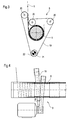
- FIG. 3 shows a schematic sectional view of a further embodiment a winding device 8 for winding a web 5 on a winding mandrel 6.
- the material web 5 is through a winding mandrel. 6 at least in sections wrapping around and over several pulleys 20 guided drive belt 19 of the winding device 8 wound up.
- the drive belt 19 is a drive device 21 by means of a drive roller 22nd driven, wherein the drive means 7 example, as shown Electric motor 22 may include.
- the material web can also be driven by several and pressing drive rollers to the winding mandrel be wound up.
- FIG. 4 shows a side view of the winding device 8 according to FIG It can be clearly seen that the guidance of the drive belt 19 is crossed over the web 5 and / or the mandrel 6. Of the Angle ⁇ of the entanglement is preferably adjustable.
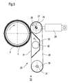
- the illustrated insertion aid 23 consists of a drive roller 24 with a drive device 25 and a deflection roller 26 with a corresponding bearing 27.
- the drive device 25 may be, for example, an electric motor or a fluid-operated motor .
- an air-permeable and circulating endless belt 28 made of a flexible material, for example a perforated plastic sheet, a braid or the like, out.
- a loading device 29 for example, a fluiddruckbeetzyerter actuator, for producing the contact between the endless belt 28 and the web 5 on the winding core 4 at.
- a vacuum channel 30 is arranged, which is open to the belt run 31 on the side of the outgoing web 5.
- This vacuum channel 30 is provided with a device 32 for generating a negative pressure p U , which acts on the open side of the vacuum channel 30 by the revolving endless belt 28 and for the detachment of the web start from the winding core 4 and its reliable transport to an inlet point 33 no longer shown a waste treatment facility ("Abschschwartzigarre").
Landscapes
- Replacement Of Web Rolls (AREA)
- Winding Of Webs (AREA)
Abstract
Description
- Figur 1
- eine perspektivische Ansicht einer Tambourablagestation, in der eine Materialbahn durch ein Antriebsband wendelförmig aufgewickelt wird;
- Figur 2
- eine mit einem Druckluftantrieb betriebene Aufwickelvorrichtung zum Aufwickeln einer Materialbahn auf einen Wickeldorn;
- Figur 3
- eine schematisierte Schnittdarstellung einer weiteren Ausführungsform einer Aufwickeleinrichtung zum Aufwickeln einer Materialbahn auf einen Wickeldorn; und
- Figur 4
- eine Seitenansicht der Aufwickeleinrichtung gemäß Figur 3; und
- Figur 5
- eine schematisierte Seitenansicht einer bevorzugten Ausführungsform einer Einführhilfe.
- 1
- Tambourablagestation
- 2
- Lagergestell
- 3
- Wickeltambour
- 4
- Wickelkern
- 5
- Materialbahn
- 6
- Wickeldorn
- 7
- Antriebseinrichtung
- 8
- Aufwickeleinrichtung
- 9
- Wellenzapfen
- 10
- Halterung
- 11
- Schacht
- 12
- Messer
- 13
- Messer
- 14
- Führungskanal
- 15
- Zuführleitung
- 16
- Auslass
- 17
- Auslass
- 18
- Schlitz
- 19
- Antriebsriemen
- 20
- Umlenkrolle
- 21
- Antriebsrolle
- 22
- Elektromotor
- 23
- Einführhilfe
- 24
- Antriebsrolle
- 25
- Antriebseinrichtung
- 26
- Umlenkrolle
- 27
- Lagerung
- 28
- Endlosband
- 29
- Belastungseinrichtung
- 30
- Vakuumkanal
- 31
- Bandtrum
- 32
- Einrichtung
- 33
- Einlaufstelle
- pU
- Unterdruck
- α
- Winkel (Wickeltambour - Wickeldorn)
- β
- Winkel (Verschränkung)
Claims (11)
- Tambourablagestation (1) mit einem Wickeltambour (3), der einen mit einem Wickel einer Materialbahn (5) bewickelten Wickelkern (4) umfasst, wobei der Wickeltambour (3) durch eine Antriebseinrichtung antreibbar ist, und mit einem einseitig befestigten und feststehenden Wickeldorn (6), der im Abrollbereich des Wickeltambours (3) unter einem Winkel (α) zur Längsachse des Wickeltambours (3) angeordnet ist und auf den die Materialbahn (5) von dem Wickeltambour (3) mittels einer Aufwickeleinrichtung (8) wendelförmig aufwickelbar ist.
- Tambourablagestation (1) nach Anspruch 1,
dadurch gekennzeichnet, dass der Winkel (α) einen Wert im Bereich von größer 0 und kleiner 90°, vorzugsweise im Bereich von 5 und 45°, aufweist. - Tambourablagestation (1) nach Anspruch 1 oder 2,
dadurch gekennzeichnet, dass die Materialbahn (5) durch einen den Wickeldorn (6) umschlingenden Antriebsriemen (19) der Aufwickeleinrichtung (8) oder durch eine die Materialbahn (5) an den Wickeldorn (6) anpressende Antriebsrolle auf den Wickeldorn (6) aufwickelbar ist. - Tambourablagestation (1) nach Anspruch 3,
dadurch gekennzeichnet, dass die Riemenführung gegenüber der Materialbahn (5) und/oder dem Wickeldorn (6) verschränkt ist. - Tambourablagestation (1) nach einem der vorhergehenden Ansprüche,
dadurch gekennzeichnet, dass die Materialbahn (5) durch einen Druckluftantrieb, insbesondere durch einen Zyklon, auf den Wickeldorn (6) aufwickelbar ist. - Tambourablagestation (1) nach einem der vorhergehenden Ansprüche,
dadurch gekennzeichnet, dass der Wickeldorn (6) von einem, insbesondere asymmetrisch mit Schlitzen (18) ausgestatteten, Führungskanal (14) zur Führung der wendelförmig aufgewickelten Materialbahn (5) umgeben ist oder
dass eine, insbesondere asymmetrisch mit Schlitzen (18) ausgestattete, Führungswanne auf der Unterseite des Wickeldorns (6) angeordnet ist. - Tambourablagestation (1) nach Anspruch 6,
dadurch gekennzeichnet, dass der Führungskanal (14) beziehungsweise die Führungswanne einen kreis- oder schneckenförmigen Querschnitt hat. - Tambourablagestation (1) nach einem der vorhergehenden Ansprüche,
dadurch gekennzeichnet, dass der Wickeldorn (6) einen inneren Kanal aufweist, aus dem über mantelseitige Bohrungen Druckluft gegen die wickeldornseitige Fläche der Materialbahn (5) pressbar ist. - Tambourablagestation (1) nach einem der vorhergehenden Ansprüche,
dadurch gekennzeichnet, dass die Materialbahn (5) dem einseitig befestigten und feststehenden Wickeldorn (6) zumindest mittels einer vorzugsweise ein Endlosband (28) aufweisenden Einführhilfe (23) zuführbar ist. - Tambourablagestation (1) nach einem der vorhergehenden Ansprüche,
dadurch gekennzeichnet, dass die wendelförmig gewickelte und von dem Wickeldorn (6) herabgleitende Materialbahn (5) einer Zerkleinerungseinheit, insbesondere zwei mit einander zusammenwirkenden Messern (12, 13) oder mit Zähnen oder Stacheln versehenen Walzen, zuführbar ist. - Tambourablagestation (1) nach einem der vorhergehenden Ansprüche,
dadurch gekennzeichnet, dass die von der Zerkleinerungseinheit oder unmittelbar vom freien Ende des Wickeldorns (6) gleitende Materialbahn (5) einem Förderband, einem zu einem Auflöser führenden Schacht (11) oder einer Absaugeinrichtung zuführbar ist.
Applications Claiming Priority (2)
| Application Number | Priority Date | Filing Date | Title |
|---|---|---|---|
| DE10343421 | 2003-09-19 | ||
| DE10343421A DE10343421A1 (de) | 2003-09-19 | 2003-09-19 | Vorrichtung und Verfahren zum Entfernen von Ausschuss einer Materialbahn von einem Wickeltambour |
Publications (2)
| Publication Number | Publication Date |
|---|---|
| EP1516840A1 true EP1516840A1 (de) | 2005-03-23 |
| EP1516840B1 EP1516840B1 (de) | 2008-03-19 |
Family
ID=34177838
Family Applications (1)
| Application Number | Title | Priority Date | Filing Date |
|---|---|---|---|
| EP04104400A Expired - Lifetime EP1516840B1 (de) | 2003-09-19 | 2004-09-13 | Vorrichtung zum Entfernen von Ausschuss einer Materialbahn von einem Wickeltambour |
Country Status (3)
| Country | Link |
|---|---|
| EP (1) | EP1516840B1 (de) |
| AT (1) | ATE389611T1 (de) |
| DE (2) | DE10343421A1 (de) |
Citations (3)
| Publication number | Priority date | Publication date | Assignee | Title |
|---|---|---|---|---|
| DE8618308U1 (de) * | 1986-07-09 | 1986-08-21 | Reichold, Peter, 5650 Solingen | Abwickelvorrichtung |
| DE3811138A1 (de) * | 1987-11-12 | 1989-06-01 | Hamada Printing Press | Verfahren und vorrichtung zum behandeln des endabschnitts von aufgerolltem papier |
| DE4141242A1 (de) * | 1991-12-14 | 1993-06-17 | Roland Man Druckmasch | Verfahren und vorrichtung zur vorbereitung des anfanges einer ersatz-wickelrolle fuer den fliegenden rollenwechsel |
Family Cites Families (6)
| Publication number | Priority date | Publication date | Assignee | Title |
|---|---|---|---|---|
| US2540897A (en) * | 1947-06-12 | 1951-02-06 | Jr Charles A Lindeman | No-rewind reel projector |
| US2657866A (en) * | 1949-07-26 | 1953-11-03 | Lungstrom Henry | Uniform tension maintaining device |
| DE1244245B (de) * | 1964-01-11 | 1967-07-13 | Philips Patentverwaltung | Umspulvorrichtung fuer bandfoermige Aufzeichnungstraeger |
| DE2106865C2 (de) * | 1971-02-13 | 1982-09-09 | Agfa-Gevaert Ag, 5090 Leverkusen | Bandwickelautomat |
| FR2488187A1 (fr) * | 1980-08-08 | 1982-02-12 | Shinshu Seiki Kk | Imprimante de petite taille |
| DE29721131U1 (de) * | 1997-10-10 | 1998-04-09 | Spiromaskiner A/S, Gjoevik | Vorrichtung zum Abwickeln eines Bandes von einer Spule |
-
2003
- 2003-09-19 DE DE10343421A patent/DE10343421A1/de not_active Withdrawn
-
2004
- 2004-09-13 EP EP04104400A patent/EP1516840B1/de not_active Expired - Lifetime
- 2004-09-13 DE DE502004006556T patent/DE502004006556D1/de not_active Expired - Fee Related
- 2004-09-13 AT AT04104400T patent/ATE389611T1/de not_active IP Right Cessation
Patent Citations (3)
| Publication number | Priority date | Publication date | Assignee | Title |
|---|---|---|---|---|
| DE8618308U1 (de) * | 1986-07-09 | 1986-08-21 | Reichold, Peter, 5650 Solingen | Abwickelvorrichtung |
| DE3811138A1 (de) * | 1987-11-12 | 1989-06-01 | Hamada Printing Press | Verfahren und vorrichtung zum behandeln des endabschnitts von aufgerolltem papier |
| DE4141242A1 (de) * | 1991-12-14 | 1993-06-17 | Roland Man Druckmasch | Verfahren und vorrichtung zur vorbereitung des anfanges einer ersatz-wickelrolle fuer den fliegenden rollenwechsel |
Also Published As
| Publication number | Publication date |
|---|---|
| DE502004006556D1 (de) | 2008-04-30 |
| ATE389611T1 (de) | 2008-04-15 |
| EP1516840B1 (de) | 2008-03-19 |
| DE10343421A1 (de) | 2005-04-14 |
Similar Documents
| Publication | Publication Date | Title |
|---|---|---|
| DE2818777C2 (de) | Wickelmaschine für Papierbahnen | |
| EP0799337B1 (de) | Wickelvorrichtung | |
| EP0995707B1 (de) | Wickelmaschine | |
| DE102006057101A1 (de) | Vorrichtungen und Verfahren zur Herstellung von Faserbündeln | |
| AT414123B (de) | Vorrichtung und verfahren zum abrollen von draht | |
| EP0792714A1 (de) | Drahtlaufsystem für eine Funkenerosionsvorrichtung | |
| EP2803609B1 (de) | Maschine zum Aufwickeln von bahnförmigen Materialien | |
| DE69807755T2 (de) | Druckwarenwickler und wickelverfahren | |
| EP0997415A1 (de) | Wickelmaschine | |
| DE3916740A1 (de) | Textilmaschine mit verstellbarer anpresswalzenanordnung | |
| DE69708979T2 (de) | Verfahren und Vorrichtung zum Aufwickeln einer Papierbahn | |
| EP1516840B1 (de) | Vorrichtung zum Entfernen von Ausschuss einer Materialbahn von einem Wickeltambour | |
| DE102006059638A1 (de) | Maschine zur Herstellung von Papier-Polstern | |
| DE112011100037B4 (de) | Speicher für Drahtmaterial | |
| DE19913219A1 (de) | Verfahren und Vorrichtung zum Aufführen einer Materialbahn auf einen Tambour | |
| DE19907550A1 (de) | Verfahren und Vorrichtung zum Aufführen einer Materialbahn auf einen Tambour | |
| DE102008041424A1 (de) | Vorrichtung und Verfahren zur Verarbeitung einer laufenden Materialbahn | |
| EP1997755B1 (de) | Vorrichtung zum Abschwarten eines Wickels einer Materialbahn von einem Wickeltambour | |
| EP1535870B1 (de) | Wickelmaschine zum kontinuierlichen Aufwickeln einer Materialbahn | |
| EP2445819A1 (de) | Wickelmaschine zum kontinuierlichen aufwickeln einer faserstoffbahn | |
| EP1026302B1 (de) | Vorrichtung zum Aufwickeln eines Faservlieses | |
| DE4002894C2 (de) | Aufwickelvorrichtung fuer eine materialbahn | |
| DE102019110059A1 (de) | Schneidstation für Faserbahnen und Verfahren zum Schneiden von Faserbahnen | |
| EP1950156B1 (de) | Verfahren zum Abschwarten eines Wickels einer Materialbahn von einem Wickeltambour und Einrichtung zur Durchführung des Verfahrens | |
| EP1038065B1 (de) | Überführungsvorrichtung |
Legal Events
| Date | Code | Title | Description |
|---|---|---|---|
| PUAI | Public reference made under article 153(3) epc to a published international application that has entered the european phase |
Free format text: ORIGINAL CODE: 0009012 |
|
| AK | Designated contracting states |
Kind code of ref document: A1 Designated state(s): AT BE BG CH CY CZ DE DK EE ES FI FR GB GR HU IE IT LI LU MC NL PL PT RO SE SI SK TR |
|
| AX | Request for extension of the european patent |
Extension state: AL HR LT LV MK |
|
| 17P | Request for examination filed |
Effective date: 20050923 |
|
| AKX | Designation fees paid |
Designated state(s): AT BE BG CH CY CZ DE DK EE ES FI FR GB GR HU IE IT LI LU MC NL PL PT RO SE SI SK TR |
|
| RAP1 | Party data changed (applicant data changed or rights of an application transferred) |
Owner name: VOITH PATENT GMBH |
|
| 17Q | First examination report despatched |
Effective date: 20070516 |
|
| GRAP | Despatch of communication of intention to grant a patent |
Free format text: ORIGINAL CODE: EPIDOSNIGR1 |
|
| GRAS | Grant fee paid |
Free format text: ORIGINAL CODE: EPIDOSNIGR3 |
|
| GRAA | (expected) grant |
Free format text: ORIGINAL CODE: 0009210 |
|
| AK | Designated contracting states |
Kind code of ref document: B1 Designated state(s): AT BE BG CH CY CZ DE DK EE ES FI FR GB GR HU IE IT LI LU MC NL PL PT RO SE SI SK TR |
|
| REG | Reference to a national code |
Ref country code: GB Ref legal event code: FG4D Free format text: NOT ENGLISH |
|
| REG | Reference to a national code |
Ref country code: CH Ref legal event code: EP |
|
| REF | Corresponds to: |
Ref document number: 502004006556 Country of ref document: DE Date of ref document: 20080430 Kind code of ref document: P |
|
| REG | Reference to a national code |
Ref country code: IE Ref legal event code: FG4D Free format text: LANGUAGE OF EP DOCUMENT: GERMAN |
|
| REG | Reference to a national code |
Ref country code: SE Ref legal event code: TRGR |
|
| NLV1 | Nl: lapsed or annulled due to failure to fulfill the requirements of art. 29p and 29m of the patents act | ||
| PG25 | Lapsed in a contracting state [announced via postgrant information from national office to epo] |
Ref country code: PL Free format text: LAPSE BECAUSE OF FAILURE TO SUBMIT A TRANSLATION OF THE DESCRIPTION OR TO PAY THE FEE WITHIN THE PRESCRIBED TIME-LIMIT Effective date: 20080319 Ref country code: SI Free format text: LAPSE BECAUSE OF FAILURE TO SUBMIT A TRANSLATION OF THE DESCRIPTION OR TO PAY THE FEE WITHIN THE PRESCRIBED TIME-LIMIT Effective date: 20080319 |
|
| REG | Reference to a national code |
Ref country code: IE Ref legal event code: FD4D |
|
| PG25 | Lapsed in a contracting state [announced via postgrant information from national office to epo] |
Ref country code: PT Free format text: LAPSE BECAUSE OF FAILURE TO SUBMIT A TRANSLATION OF THE DESCRIPTION OR TO PAY THE FEE WITHIN THE PRESCRIBED TIME-LIMIT Effective date: 20080826 Ref country code: SK Free format text: LAPSE BECAUSE OF FAILURE TO SUBMIT A TRANSLATION OF THE DESCRIPTION OR TO PAY THE FEE WITHIN THE PRESCRIBED TIME-LIMIT Effective date: 20080319 Ref country code: CZ Free format text: LAPSE BECAUSE OF FAILURE TO SUBMIT A TRANSLATION OF THE DESCRIPTION OR TO PAY THE FEE WITHIN THE PRESCRIBED TIME-LIMIT Effective date: 20080319 Ref country code: ES Free format text: LAPSE BECAUSE OF FAILURE TO SUBMIT A TRANSLATION OF THE DESCRIPTION OR TO PAY THE FEE WITHIN THE PRESCRIBED TIME-LIMIT Effective date: 20080630 |
|
| PG25 | Lapsed in a contracting state [announced via postgrant information from national office to epo] |
Ref country code: NL Free format text: LAPSE BECAUSE OF FAILURE TO SUBMIT A TRANSLATION OF THE DESCRIPTION OR TO PAY THE FEE WITHIN THE PRESCRIBED TIME-LIMIT Effective date: 20080319 Ref country code: RO Free format text: LAPSE BECAUSE OF FAILURE TO SUBMIT A TRANSLATION OF THE DESCRIPTION OR TO PAY THE FEE WITHIN THE PRESCRIBED TIME-LIMIT Effective date: 20080319 |
|
| EN | Fr: translation not filed | ||
| PLBE | No opposition filed within time limit |
Free format text: ORIGINAL CODE: 0009261 |
|
| STAA | Information on the status of an ep patent application or granted ep patent |
Free format text: STATUS: NO OPPOSITION FILED WITHIN TIME LIMIT |
|
| PG25 | Lapsed in a contracting state [announced via postgrant information from national office to epo] |
Ref country code: IE Free format text: LAPSE BECAUSE OF FAILURE TO SUBMIT A TRANSLATION OF THE DESCRIPTION OR TO PAY THE FEE WITHIN THE PRESCRIBED TIME-LIMIT Effective date: 20080319 Ref country code: DK Free format text: LAPSE BECAUSE OF FAILURE TO SUBMIT A TRANSLATION OF THE DESCRIPTION OR TO PAY THE FEE WITHIN THE PRESCRIBED TIME-LIMIT Effective date: 20080319 |
|
| 26N | No opposition filed |
Effective date: 20081222 |
|
| BERE | Be: lapsed |
Owner name: VOITH PATENT G.M.B.H. Effective date: 20080930 |
|
| PG25 | Lapsed in a contracting state [announced via postgrant information from national office to epo] |
Ref country code: EE Free format text: LAPSE BECAUSE OF FAILURE TO SUBMIT A TRANSLATION OF THE DESCRIPTION OR TO PAY THE FEE WITHIN THE PRESCRIBED TIME-LIMIT Effective date: 20080319 Ref country code: MC Free format text: LAPSE BECAUSE OF NON-PAYMENT OF DUE FEES Effective date: 20080930 Ref country code: BG Free format text: LAPSE BECAUSE OF FAILURE TO SUBMIT A TRANSLATION OF THE DESCRIPTION OR TO PAY THE FEE WITHIN THE PRESCRIBED TIME-LIMIT Effective date: 20080619 |
|
| REG | Reference to a national code |
Ref country code: CH Ref legal event code: PL |
|
| GBPC | Gb: european patent ceased through non-payment of renewal fee |
Effective date: 20080913 |
|
| PG25 | Lapsed in a contracting state [announced via postgrant information from national office to epo] |
Ref country code: FI Free format text: LAPSE BECAUSE OF NON-PAYMENT OF DUE FEES Effective date: 20080913 |
|
| PG25 | Lapsed in a contracting state [announced via postgrant information from national office to epo] |
Ref country code: BE Free format text: LAPSE BECAUSE OF NON-PAYMENT OF DUE FEES Effective date: 20080930 |
|
| PG25 | Lapsed in a contracting state [announced via postgrant information from national office to epo] |
Ref country code: IT Free format text: LAPSE BECAUSE OF NON-PAYMENT OF DUE FEES Effective date: 20080913 Ref country code: DE Free format text: LAPSE BECAUSE OF NON-PAYMENT OF DUE FEES Effective date: 20090401 |
|
| PG25 | Lapsed in a contracting state [announced via postgrant information from national office to epo] |
Ref country code: CY Free format text: LAPSE BECAUSE OF FAILURE TO SUBMIT A TRANSLATION OF THE DESCRIPTION OR TO PAY THE FEE WITHIN THE PRESCRIBED TIME-LIMIT Effective date: 20080319 |
|
| PG25 | Lapsed in a contracting state [announced via postgrant information from national office to epo] |
Ref country code: LI Free format text: LAPSE BECAUSE OF NON-PAYMENT OF DUE FEES Effective date: 20080930 Ref country code: AT Free format text: LAPSE BECAUSE OF NON-PAYMENT OF DUE FEES Effective date: 20080913 Ref country code: CH Free format text: LAPSE BECAUSE OF NON-PAYMENT OF DUE FEES Effective date: 20080930 |
|
| PG25 | Lapsed in a contracting state [announced via postgrant information from national office to epo] |
Ref country code: GB Free format text: LAPSE BECAUSE OF NON-PAYMENT OF DUE FEES Effective date: 20080913 |
|
| PG25 | Lapsed in a contracting state [announced via postgrant information from national office to epo] |
Ref country code: HU Free format text: LAPSE BECAUSE OF FAILURE TO SUBMIT A TRANSLATION OF THE DESCRIPTION OR TO PAY THE FEE WITHIN THE PRESCRIBED TIME-LIMIT Effective date: 20080920 Ref country code: SE Free format text: LAPSE BECAUSE OF NON-PAYMENT OF DUE FEES Effective date: 20080914 Ref country code: LU Free format text: LAPSE BECAUSE OF NON-PAYMENT OF DUE FEES Effective date: 20080913 |
|
| PG25 | Lapsed in a contracting state [announced via postgrant information from national office to epo] |
Ref country code: TR Free format text: LAPSE BECAUSE OF FAILURE TO SUBMIT A TRANSLATION OF THE DESCRIPTION OR TO PAY THE FEE WITHIN THE PRESCRIBED TIME-LIMIT Effective date: 20080319 |
|
| PG25 | Lapsed in a contracting state [announced via postgrant information from national office to epo] |
Ref country code: GR Free format text: LAPSE BECAUSE OF FAILURE TO SUBMIT A TRANSLATION OF THE DESCRIPTION OR TO PAY THE FEE WITHIN THE PRESCRIBED TIME-LIMIT Effective date: 20080620 |
|
| PG25 | Lapsed in a contracting state [announced via postgrant information from national office to epo] |
Ref country code: FR Free format text: LAPSE BECAUSE OF FAILURE TO SUBMIT A TRANSLATION OF THE DESCRIPTION OR TO PAY THE FEE WITHIN THE PRESCRIBED TIME-LIMIT Effective date: 20090109 |