EP1516608A2 - Rollstuhlrahmen - Google Patents
Rollstuhlrahmen Download PDFInfo
- Publication number
- EP1516608A2 EP1516608A2 EP04021201A EP04021201A EP1516608A2 EP 1516608 A2 EP1516608 A2 EP 1516608A2 EP 04021201 A EP04021201 A EP 04021201A EP 04021201 A EP04021201 A EP 04021201A EP 1516608 A2 EP1516608 A2 EP 1516608A2
- Authority
- EP
- European Patent Office
- Prior art keywords
- wheelchair
- frame
- profile
- seat
- side part
- Prior art date
- Legal status (The legal status is an assumption and is not a legal conclusion. Google has not performed a legal analysis and makes no representation as to the accuracy of the status listed.)
- Granted
Links
Images


Classifications
-
- A—HUMAN NECESSITIES
- A61—MEDICAL OR VETERINARY SCIENCE; HYGIENE
- A61G—TRANSPORT, PERSONAL CONVEYANCES, OR ACCOMMODATION SPECIALLY ADAPTED FOR PATIENTS OR DISABLED PERSONS; OPERATING TABLES OR CHAIRS; CHAIRS FOR DENTISTRY; FUNERAL DEVICES
- A61G5/00—Chairs or personal conveyances specially adapted for patients or disabled persons, e.g. wheelchairs
- A61G5/02—Chairs or personal conveyances specially adapted for patients or disabled persons, e.g. wheelchairs propelled by the patient or disabled person
-
- A—HUMAN NECESSITIES
- A61—MEDICAL OR VETERINARY SCIENCE; HYGIENE
- A61G—TRANSPORT, PERSONAL CONVEYANCES, OR ACCOMMODATION SPECIALLY ADAPTED FOR PATIENTS OR DISABLED PERSONS; OPERATING TABLES OR CHAIRS; CHAIRS FOR DENTISTRY; FUNERAL DEVICES
- A61G5/00—Chairs or personal conveyances specially adapted for patients or disabled persons, e.g. wheelchairs
- A61G5/10—Parts, details or accessories
- A61G5/1056—Arrangements for adjusting the seat
- A61G5/1067—Arrangements for adjusting the seat adjusting the backrest relative to the seat portion
-
- A—HUMAN NECESSITIES
- A61—MEDICAL OR VETERINARY SCIENCE; HYGIENE
- A61G—TRANSPORT, PERSONAL CONVEYANCES, OR ACCOMMODATION SPECIALLY ADAPTED FOR PATIENTS OR DISABLED PERSONS; OPERATING TABLES OR CHAIRS; CHAIRS FOR DENTISTRY; FUNERAL DEVICES
- A61G5/00—Chairs or personal conveyances specially adapted for patients or disabled persons, e.g. wheelchairs
- A61G5/10—Parts, details or accessories
- A61G5/1056—Arrangements for adjusting the seat
- A61G5/107—Arrangements for adjusting the seat positioning the whole seat forward or rearward
-
- A—HUMAN NECESSITIES
- A61—MEDICAL OR VETERINARY SCIENCE; HYGIENE
- A61G—TRANSPORT, PERSONAL CONVEYANCES, OR ACCOMMODATION SPECIALLY ADAPTED FOR PATIENTS OR DISABLED PERSONS; OPERATING TABLES OR CHAIRS; CHAIRS FOR DENTISTRY; FUNERAL DEVICES
- A61G5/00—Chairs or personal conveyances specially adapted for patients or disabled persons, e.g. wheelchairs
- A61G5/10—Parts, details or accessories
- A61G5/1089—Anti-tip devices
-
- A—HUMAN NECESSITIES
- A61—MEDICAL OR VETERINARY SCIENCE; HYGIENE
- A61G—TRANSPORT, PERSONAL CONVEYANCES, OR ACCOMMODATION SPECIALLY ADAPTED FOR PATIENTS OR DISABLED PERSONS; OPERATING TABLES OR CHAIRS; CHAIRS FOR DENTISTRY; FUNERAL DEVICES
- A61G5/00—Chairs or personal conveyances specially adapted for patients or disabled persons, e.g. wheelchairs
- A61G5/10—Parts, details or accessories
- A61G5/12—Rests specially adapted therefor, e.g. for the head or the feet
- A61G5/128—Rests specially adapted therefor, e.g. for the head or the feet for feet
Definitions
- the invention relates to a wheelchair frame according to the Features of the preamble of the main claim.
- the invention relates to a wheelchair frame for one with rear wheels and steerable front wheels provided wheelchair, with a right and a left side frame and with an arranged between the side frames, Seat provided with a backrest.
- the invention is for rigid wheelchair frames as well For wheelchair frames that can be folded laterally, applicable.
- the invention is based on the object, a wheelchair frame to create the type mentioned, which in a simple Structure and simple, cost-effective manufacturability the Disadvantages of the prior art avoids and also characterized by a visually appealing shape, a frame profile which, with a simple structure and easier, cost-effective manufacturability simple and easy attachment various attachments allows and with a wheelchair side part is provided, which in a simple Structure and cost manufacturability, the disadvantages of Prevented prior art and is easy to install.
- the side frame in Form of an arcuate profile is formed, which is at least partially above the rear wheel from the area of Backrest extends to a hinge region of the front wheel.
- the wheelchair frame according to the invention is characterized by a Series of significant benefits.
- the side frame Due to the design of the side frame in the form of a single, arcuate profile results in a very low production cost. It is only necessary, this one Deform or bend the profile accordingly. At the front End of the profile, the steerable front wheels can be attached directly become.
- the profile extends at least to the Area of the backrest, but it can be even further backwards be extended. According to the invention are thus no further lower horizontal struts required, rather the profile is the load-bearing construction element of the wheelchair frame or the two side frames.
- a rear strut is attached, whose free end is an axle for the rear wheel outsourced.
- the rear strut can be inclined down and extend forward so that the axle of the rear wheel below the seating area of the wheelchair frame is arranged.
- this connecting cross strut serves to connect the two side frames.
- the front end portions of the two side frames may be more preferable Way be connected by means of a foot plate on the front end of the two side frames is mounted. It is It is especially favorable if the footplate is in different positions mountable, so that an adaptation to the respective Body size or leg length of the user is possible.
- the seat with the backrest is more preferable Way designed as a seat module.
- this seat module be installed separately or dismantled. It is also possible to use a separate seat shell, for example also removable and used for other purposes can be, for example, as a car seat for the disabled.
- a separate seat shell for example also removable and used for other purposes can be, for example, as a car seat for the disabled.
- the wheelchair frame according to the invention in particular is suitable for children's wheelchairs, this variant is special advantageous.
- the seat module is preferably in each case designed and mounted that a variety of mounting positions achievable are. This allows the seat height to be adjusted easily, The same applies to the seat depth and the relative Position to the axle of the rear wheels.
- the seat module is additional due to different mounting points at an angle to Horizontally inclined mountable. This makes it possible, different to realize inclined seating positions.
- the seat module comprises in a favorable development of the invention each a lateral, substantially horizontal seatstay, for example, on the arcuate profile (front End) and on the rear strut (rear end) be mounted can.
- These mounting points can be variable, for example by providing a number of different holes, to ensure any removable screw connection.
- the backrest can be adjusted with the horizontal Be struts bolted. Again, it is possible to different To select mounting positions so that the seat depth in simple way is variable.
- the back struts can be extended upwards in a favorable manner form part of a sliding tube, the two Sliding tubes are connected by means of a bracket. hereby a slide is formed whose sliding forces directly into the The wheelchair can be initiated and completely independent from the seat module and its position. The position the sliding tubes and their arrangement is more preferred Way chosen so that this far behind the rear axle (drive axle) lie. This results in a very easy maneuvering of the wheelchair by an attendant.
- the sliding tubes can also be formed kinkable or collapsible be to reduce the dimensions of the wheelchair during transport to be able to.
- a tilt support On the transverse support, which supports the axle of the rear wheels, a tilt support can be stored.
- This tilt support can be releasably formed to the folding of the wheelchair frame to simplify with removed rear wheels. Cheap it is, if only a central tilt support is provided because this then a companion when pushing the wheelchair not disabled.
- the elliptical or arcuate shape of the invention Profile of the page frame still allows this profile to use directly as a lateral body support, so can be dispensed with separate armrests or the like.
- the profile of the side frame is preferably designed to that a variety of attachments against rotation can be mounted on the torsionally stiff profile.
- the frame profile a central, flat central region, at whose both sides each followed by a thickened area.
- the middle part can be provided with holes or other Have recesses.
- the other recesses can, for example serve to reduce the overall weight of the profile, without compromising its structural integrity. Smaller, mostly cylindrical recesses can be provided be to attach attachments in different positions.
- the profile can also be modular with regular Be provided holes in the middle area.
- longitudinal slots or the like in the middle section can be extend in the parallel direction of the frame profile, they can but also be inclined at an angle.
- the frame profile with a symmetrical to a median plane profile cross-section Mistake is also possible.
- the profile is asymmetrical form, for example, one of the thickened Areas other dimensions than the other thickened Area.
- the thickened portion of the profile each formed as a tube be.
- the frame profile according to the invention can in a simple manner as Extruded be prepared, for example, aluminum or another suitable alloy. This results a particularly cost-effective production possibility.
- At least one mounting element on the flat central region is fastened. This can, for example, against rotation be applied to the thickened areas. Consequently results in a tilting or rotation, which is particularly simple and highly effective. It can, for example also just a connecting element, such as a Screw or a rivet sufficient to secure attachment to ensure.
- the flat middle area offers a sufficient contact surface to ensure adequate power transmission sure.
- the wheelchair side member according to the invention has at its Basic body in one piece on a fastening part, which on a frame tube of the wheelchair is clipped.
- the solution according to the invention is characterized by a number of significant Advantages.
- the wheelchair side part is rather only imprinted or clipped on. In accordance with simpler Way it can be dismantled anytime again.
- the attachment part of the wheelchair side part a Cross-section, which matches the outer contour is formed of the frame tube and this engages behind accordingly. This results in a secure fit of the wheelchair side part on the frame, which additionally provides a security against rotation can be guaranteed.
- the fastening part preferably has over its entire Length equal to a cross section.
- the wheelchair side part on different pipe sections of a Wheelchair frame are clipped.
- the wheelchair side part or its attachment part in the mounted state in the Essentially laterally or horizontally extending upper Thigh includes.
- the wheelchair frame tube is additionally covered others, the leg can be made so wide that he serves as an armrest and, for example, via a Part of the wheel or over the entire wheel extends and thus similar to a mudguard against dirt from the wheel or protects against injuries to the wheelchair user.
- the attachment part of the wheelchair side part may have an upper and a lower leg, so that in the Substantially U-shaped cross-section results through which the frame tube can be safely grasped.
- the main body of the wheelchair side part from the side of the seat of the wheelchair is clipped.
- the wheelchair side part can be made of a thin, lightweight Be made of material, preferably made of plastic.
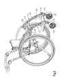
- Fig. 1 shows a wheelchair with rear wheels 1 and steerable front wheels 2.
- the rear wheels 1 are in common Formed way, so waived their description can be. They include, for example, a gripping ring as well not shown spokes.
- the front wheels 2 are respectively rotatably mounted on a fork, which is not shown vertical axis pivotally mounted on a bearing block 18 are.
- the wheelchair according to the invention comprises a right side frame 3 and a left side frame 4. These are each in the form of an arcuate, for example, partially elliptical Profiles trained. The profile will be communicated in detail explained with the Fig. 3.
- the rear, upper end of the respective profile of the side frame 3, 4 is with a backstay 7 (right) and 8 (left) connected to the lower end of a cross member 9 (pipe) attached is, which the axes not shown for the Rear wheels 1 stores.
- the attachment of the crossbar 9 can For example, via a clamp connection, as this is shown in Figs. 1 and 2.
- the rear struts 7, 8 are extended upward and form Sliding tubes 12, 13, whose end portions by means of a bracket 14th connected in this way a slide for the To form a wheelchair.
- the profiles of the side frames 3 and 4 are respectively arranged and dimensions that at the same time an armrest or form lateral support of the wheelchair frame.
- Farther are the profiles of the side frames 3, 4 with a variety of Recesses or mounting holes provided. These can be used for Part to save weight, on the other hand it acts around cylindrical recesses, through which screws are feasible to attach, for example, the bearing blocks 18.
- a foot plate 10 which in the in Fig. 1 is screwed manner shown and the lower front ends of the two side frames 3, 4 connects.
- the wheelchair also has a backrest 5 and a Seat 6, which are designed as a module and on lateral, essentially horizontal seat stays 11 are mounted.
- a backrest 5 and a Seat 6 which are designed as a module and on lateral, essentially horizontal seat stays 11 are mounted.
- the seat stays 11 at their front and rear end portions each provided with a plurality of recesses.
- the back struts 20 On the seat stays 11 are substantially vertical back struts 20 attached, which in the usual way the backrest 5 store. As shown in FIG. 2, the back struts 20 also adjustable screwed to the side frame 3 and 4 respectively. Due to the large number of provided mounting holes There is the possibility of the inclination of the back braces 20 to adjust. The same applies to the assembly the horizontal seat stays 11. This can also be the seat depth be easily adapted.
- Fig. 2 further shows that for storage of the front wheels 2 on the forks 17 a plurality of mounting points are provided to to adjust the height.
- Fig. 1 further shows a central tilt support 15, which is mounted on the transverse strut 9.
- the tilt support 15 can in an essentially vertical bearing tube 21 received rotatably be to assist in folding the wheelchair frame removed rear wheels 21 to be pivoted forward. This pivoting can also during a manual operation of the Wheelchair to give the user the opportunity to lift the front wheels 2 accordingly.
- a side cover 16 is shown, the for widening the armrest and for lateral protection the side frame profiles 3, 4 can be mounted.
- the invention comprises Frame profile a flat central region 101, which in the Has substantially rectangular cross-section. Subsequently to the two narrow sides of the flat central region 101 is in one piece each a thickened area 102 and 103rd educated.
- the thickened regions 102, 103 are as tube profile designed while the shallow mid-range is full Material exists.
- the profile is with a Cross-section, which is symmetrical about a central plane 104 is.
- Fig. 5 shows an enlarged view of a curved Design of the frame profile. It can be seen that a plurality of recesses 105 may be provided to To perform fasteners, such as screws or rivets. From this, the modular structure is apparent. Furthermore, larger recesses 106 may be provided, the can help reduce weight and continue to become one lead to an attractive visual appearance.
- FIG. 5 shows the attachment of a mounting member 107th by means of screws 109, 110. It can be seen in particular that the mounting member 107 against the thickened areas 102, 103, so that there is an anti-rotation.
- Fig. 4 shows an application example of the invention Frame profile in a wheelchair frame, its side frame 110, 111 each made of the frame profile according to the invention are. It can be seen that, for example, seatstays 112 in a simple manner on the frame profile according to the invention can be mounted, wherein the mounting member 107 as a counter-pressure plate can work. Similarly, are lateral Angle of a foot plate 113 bolted. Also the tilt and non-rotating mounting of bearing blocks 114 for front wheels 115 takes place in the manner described.
- Fig. 6 shows a perspective view of a possible Embodiment of the wheelchair according to the invention, on which the Wheelchair side part according to the invention can be grown.
- the wheelchair shown is on both sides of a seat with each a wheelchair side member 201 according to the invention provided, which each clipped onto a lateral frame tube 202 and 203, respectively is, as for example from the sectional view Fig. 9 shows.
- the frame tubes 202, 203 which each form a side frame, arcuate.
- the lateral contour of the wheelchair side part 201 also designed arcuate, so that the wheelchair side part corresponding to the frame tubes 202 and 203, respectively can be clipped on.
- the radius of the arcuate contour is here chosen appropriately. This results in the possibility that Unclip wheelchair side part 201 at a variable position and to mount accordingly further forward or further back, depending on the position of the seat or seat module relative to the wheelchair frame.
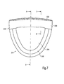
- FIGS. 7 to 10 show an embodiment of the invention Wheelchair side member 201 in more detail. It follows that this is a plate-shaped Base body 204 includes, which for example in shape a semi-ellipse may be contoured to the structural Circumstances to be adapted. It can of course Other outer contours of the base 204 are provided be.
- the base 204 includes in the shown Embodiment a circumferential reinforcing bead or rib 208.
- a fastening part 205 formed, which is a substantially U-shaped cross-section (see Figures 8 and 9).
- a vertical leg 209 is provided, which in a upper leg 206 and a lower leg 207 passes.
- the upper leg 206 is formed extended, so that he not only the frame tube 202, 203, but also a part of can cover adjacent wheel and at the same time as an arm-bearing surface can serve.
- the lower leg 207 is as shown in FIG the plate-shaped base body 204 via.
- FIGS. 8 and 9 shown on the upper leg 206 and at the bottom Leg 207 an upper bead or constriction 210 or a formed lower bead or constriction 211, through which the free cross section of the U-shape is reduced.
- elastic Deformation when sliding the fastening part 205 This results in the clip-on effect.
- This one is basically regardless of the cross-sectional shape of the frame tube 202, 203. It is understood that the fastening part 205 in terms of its dimensioning to the cross section of the frame tube 202, 203 must be adjusted.
- the upper leg 206 can be attached to its Corner areas should be rounded in order to prevent injury avoid and to give the other the visual appearance improve.
Landscapes
- Health & Medical Sciences (AREA)
- Life Sciences & Earth Sciences (AREA)
- Animal Behavior & Ethology (AREA)
- General Health & Medical Sciences (AREA)
- Public Health (AREA)
- Veterinary Medicine (AREA)
- Carriages For Children, Sleds, And Other Hand-Operated Vehicles (AREA)
- Handcart (AREA)
- Automatic Cycles, And Cycles In General (AREA)
- Non-Silver Salt Photosensitive Materials And Non-Silver Salt Photography (AREA)
Abstract
Description
- Fig. 1
- eine perspektivische Darstellung eines Ausführungsbeispiels eines erfindungsgemäßen Rollstuhlrahmens,
- Fig. 2
- eine vereinfachte Seitenansicht des in Fig. 1 gezeigten Rollstuhlrahmens,
- Fig. 3
- eine Schnittansicht durch ein erfindungsgemäßes Ausführungsbeispiel des erfindungsgemäßen Rahmenprofils,
- Fig. 4
- eine schematische, perspektivische Darstellung eines Rollstuhls unter Verwendung des erfindungsgemäßen Rahmenprofils,
- Fig. 5
- eine vergrößerte Darstellung eines Teilbereichs des in Fig. 4 gezeigten Rollstuhl-Rahmens mit einem an dem erfindungsgemäßen Rahmenprofil montierten Montageelement,
- Fig. 6
- eine perspektivische Ansicht eines Rollstuhls mit erfindungsgemäßem Rollstuhlseitenteil,
- Fig. 7
- eine Seitenansicht eines weiteren Ausführungsbeispiels eines erfindungsgemäßen Rollstuhlseitenteils,
- Fig. 8
- eine Schnittansicht längs der Linie A-B von Fig. 7,
- Fig. 9
- eine Schnittansicht längs der Linie C-D von Fig. 7, und
- Fig. 10
- eine Draufsicht auf die Anordnung gemäß Fig. 7.
- 1
- Hinterrad
- 2
- Vorderrad
- 3
- Rechter Seitenrahmen
- 4
- Linker Seitenrahmen
- 5
- Rückenlehne
- 6
- Sitz
- 7
- Rechte Rückstrebe
- 8
- Linke Rückstrebe
- 9
- Querstrebe
- 10
- Fußplatte
- 11
- Sitzstrebe
- 12
- Schieberohr rechts
- 13
- Schieberohr links
- 14
- Bügel
- 15
- Kippstütze
- 16
- Seitenabdeckung
- 17
- Gabel
- 18
- Lagerbock
- 19
- Gelenk
- 20
- Rückenstrebe
- 21
- Lagerrohr
- 101
- Flacher Mittelbereich
- 102
- Oberer verdickter Bereich
- 103
- Unterer verdickter Bereich
- 104
- Mittelebene
- 105
- Ausnehmung
- 106
- Ausnehmung
- 107
- Montageelement
- 108
- Schraube
- 109
- Schraube
- 110
- Rechter Seitenrahmen
- 111
- Linker Seitenrahmen
- 112
- Sitzstrebe
- 113
- Fußplatte
- 114
- Lagerbock
- 115
- Vorderrad
- 201
- Rollstuhlseitenteil
- 202
- Rahmenrohr
- 203
- Rahmenrohr
- 204
- Grundkörper
- 205
- Befestigungsteil
- 206
- Oberer Schenkel
- 207
- Unterer Schenkel
- 208
- Verstärkungssicke
- 209
- Vertikaler Schenkel
- 210
- Obere Wulst
- 211
- Untere Wulst
Claims (29)
- Rollstuhlrahmen für einen mit Hinterrädern (1) und lenkbaren Vorderrädern (2) versehenen Rollstuhl mit einem rechten (3) und einem linken (4) Seitenrahmen sowie mit einem zwischen den Seitenrahmen (3, 4) angeordneten, mit einer Rückenlehne (5) versehenen Sitz (6), dadurch gekennzeichnet, dass der Seitenrahmen (3, 4) in Form eines bogenförmigen Profils ausgebildet ist, welches sich zumindest teilweise oberhalb des Hinterrads (1) vom Bereich der Rückenlehne (5) aus zu einem Anlenkbereich des Vorderrads (2) erstreckt.
- Rollstuhlrahmen nach Anspruch 1, dadurch gekennzeichnet, dass an dem hinteren Bereich des Sitzrahmens (3, 4) eine Rückstrebe (7, 8) befestigt ist, deren freies Ende eine Achse für das Hinterrad (1) lagert.
- Rollstuhlrahmen nach Anspruch 2, dadurch gekennzeichnet, dass an den freien Enden der Rückstreben (7, 8) eine diese verbindende Querstrebe (9) ausgebildet ist.
- Rollstuhlrahmen nach einem der Ansprüche 1 bis 3, dadurch gekennzeichnet, dass die vorderen Endbereich der Seitenrahmen (3, 4) mittels einer Fußplatte (10) verbunden sind.
- Rollstuhlrahmen nach Anspruch 4, dadurch gekennzeichnet, dass die Fußplatte (10) in verschiedenen Positionen montierbar ist.
- Rollstuhlrahmen nach einem der Ansprüche 1 bis 5, dadurch gekennzeichnet, dass der Sitz (6) mit der Rückenlehne (5) als Sitzmodul ausgebildet und in verschiedenen Positionen an den Seitenrahmen (3, 4) montierbar ist.
- Rollstuhlrahmen nach Anspruch 6, dadurch gekennzeichnet, dass das Sitzmodul (5, 6) jeweils eine seitliche, im Wesentlichen horizontale Sitzstrebe (11) umfasst, deren Endbereiche mit den Rückenstreben (7, 8) bzw. mit dem bogenförmigen Profil des Seitenrahmens (3, 4) verbunden sind.
- Rollstuhlrahmen nach einem der Ansprüche 6 oder 7, dadurch gekennzeichnet, dass das Sitzmodul in einem Winkel zur Horizontalen zur Erzielung einer geneigten Sitzposition schräg einbaubar ist.
- Rollstuhlrahmen nach einem der Ansprüche 1 bis 8, dadurch gekennzeichnet, dass die Rückstreben (7, 8) jeweils Teil eines Schieberohrs (12, 13) sind, wobei die Schieberohre (12, 13) mittels eines Bügels (14) verbunden sind.
- Rollstuhlrahmen nach einem der Ansprüche 3 bis 9, dadurch gekennzeichnet, dass an der Querstrebe (9) lösbar eine Kippstütze (15) gelagert ist.
- Rollstuhlrahmen nach einem der Ansprüche 1 bis 10, dadurch gekennzeichnet, dass das bogenförmige Profil des Seitenrahmens (3, 4) eine Seitenabdeckung (16) lagert.
- Rahmenprofil, insbesondere für einen Rollstuhlrahmen nach einem der Ansprüche 1 bis 11, welches einen zentrischen flachen Mittelbereich (101) sowie zu beiden Seiten jeweils einen sich anschließenden verdickten Bereich (102, 103) umfasst.
- Rahmenprofil nach Anspruch 12, gekennzeichnet durch einen zu einer Mittelebene (104) symmetrischen Profilquerschnitt.
- Rahmenprofil nach Anspruch 12 oder 13, dadurch gekennzeichnet, dass der verdickte Bereich (102, 103) als Rohr ausgebildet ist.
- Rahmenprofil nach einem der Ansprüche 12 bis 14, dadurch gekennzeichnet, dass der flache Mittelbereich (101) einen im Wesentlichen rechteckigen Querschnitt aufweist.
- Rahmenprofil nach einem der Ansprüche 12 bis 15, dadurch gekennzeichnet, dass der flache Mittelbereich (101) mit zumindest einer Ausnehmung (105, 106) versehen ist.
- Rahmenprofil nach einem der Ansprüche 12 bis 16, dadurch gekennzeichnet, dass an dem flachen Mittelbereich (101) zumindest ein Montageelement (107) befestigbar ist.
- Rahmenprofil nach Anspruch 17, dadurch gekennzeichnet, dass das Montageelement (107) verdrehsicher an die verdichteten Bereiche (102, 103) anlegbar ist.
- Rollstuhlseitenteil mit einem an einem Rollstuhlrahmen lösbar befestigbaren Grundkörper (204) nach einem der Ansprüche 1 bis 18, dadurch gekennzeichnet, dass an dem Grundkörper (204) einstückig ein an ein Rahmenrohr (202, 203) des Rollstuhls anklipsbarer Befestigungsteil (205) ausgebildet ist.
- Rollstuhlseitenteil nach Anspruch 19, dadurch gekennzeichnet, dass der Befestigungsteil (205) einen Querschnitt aufweist, welcher passend zu der Außenkontur des Rahmenrohrs (202, 203) ausgebildet ist und dieses hintergreift.
- Rollstuhlseitenteil nach Anspruch 19 oder 20, dadurch gekennzeichnet, dass der Befestigungsteil (205) mit einem über im Wesentlichen seine gesamte Länge gleichen Querschnitt versehen ist.
- Rollstuhlseitenteil nach einem der Ansprüche 19 bis 21, dadurch gekennzeichnet, dass der Befestigungsteil (205) einen im montierten Zustand sich im Wesentlichen horizontal erstreckenden oberen Schenkel (206) umfasst.
- Rollstuhlseitenteil nach einem der Ansprüche 19 bis 22, dadurch gekennzeichnet, dass der Befestigungsteil (205) im Wesentlichen der Kontur eines Rades angepasst ist und dieses umgreift.
- Rollstuhlseitenteil nach einem der Ansprüche 19 bis 23, dadurch gekennzeichnet, dass der Befestigungsteil (205) einen oberen (206) und einen unteren (207), das Rahmenrohr (202, 203) im montierten Zustand hintergreifenden Schenkel umfasst.
- Rollstuhlseitenteil nach einem der Ansprüche 19 bis 24, dadurch gekennzeichnet, dass der Grundkörper (204) von der Seite des Sitzes des Rollstuhls aus anklipsbar ist.
- Rollstuhlseitenteil nach einem der Ansprüche 19 bis 25, dadurch gekennzeichnet, dass der Grundkörper (204) mit zumindest einer Verstärkungssicke (208) versehen ist.
- Rollstuhlseitenteil nach einem der Ansprüche 19 bis 26, dadurch gekennzeichnet, dass der Grundkörper (204) in der Seitenansicht abgerundet ist.
- Rollstuhlseitenteil nach einem der Ansprüche 19 bis 27, dadurch gekennzeichnet, dass der obere Schenkel (206) in der Draufsicht abgerundet ist.
- Rollstuhlseitenteil nach einem der Ansprüche 19 bis 28, dadurch gekennzeichnet, dass der Befestigungsteil (205) in der Seitenansicht bogenförmig ausgebildet ist.
Applications Claiming Priority (6)
| Application Number | Priority Date | Filing Date | Title |
|---|---|---|---|
| DE10343784 | 2003-09-22 | ||
| DE10343784A DE10343784B3 (de) | 2003-09-22 | 2003-09-22 | Rollstuhlrahmen |
| DE20314644U DE20314644U1 (de) | 2003-09-22 | 2003-09-22 | Rahmenprofil für einen Rollstuhl o.dgl. |
| DE20314644U | 2003-09-22 | ||
| DE20315420U | 2003-10-07 | ||
| DE20315420U DE20315420U1 (de) | 2003-10-07 | 2003-10-07 | Rollstuhlseitenteil |
Publications (3)
| Publication Number | Publication Date |
|---|---|
| EP1516608A2 true EP1516608A2 (de) | 2005-03-23 |
| EP1516608A3 EP1516608A3 (de) | 2005-11-16 |
| EP1516608B1 EP1516608B1 (de) | 2007-01-31 |
Family
ID=34198483
Family Applications (1)
| Application Number | Title | Priority Date | Filing Date |
|---|---|---|---|
| EP04021201A Not-in-force EP1516608B1 (de) | 2003-09-22 | 2004-09-07 | Rollstuhlrahmen |
Country Status (5)
| Country | Link |
|---|---|
| EP (1) | EP1516608B1 (de) |
| AT (1) | ATE353003T1 (de) |
| DE (1) | DE502004002823D1 (de) |
| DK (1) | DK1516608T3 (de) |
| ES (1) | ES2281728T3 (de) |
Cited By (1)
| Publication number | Priority date | Publication date | Assignee | Title |
|---|---|---|---|---|
| CN107638256A (zh) * | 2017-11-08 | 2018-01-30 | 南京康尼机电股份有限公司 | 一种轮椅车的底盘箱体 |
Citations (3)
| Publication number | Priority date | Publication date | Assignee | Title |
|---|---|---|---|---|
| EP1059075A2 (de) * | 1999-06-10 | 2000-12-13 | Herbert Brustmann | Fahrbarer Stuhl |
| DE20216312U1 (de) * | 2002-10-22 | 2003-01-09 | Rehatechnik Moeller Gmbh | Rollstuhl mit verstellbarer Sitzhöhe |
| JP2004073509A (ja) * | 2002-08-19 | 2004-03-11 | Itoki Crebio Corp | 車椅子 |
-
2004
- 2004-09-07 ES ES04021201T patent/ES2281728T3/es active Active
- 2004-09-07 DE DE502004002823T patent/DE502004002823D1/de active Active
- 2004-09-07 EP EP04021201A patent/EP1516608B1/de not_active Not-in-force
- 2004-09-07 AT AT04021201T patent/ATE353003T1/de active
- 2004-09-07 DK DK04021201T patent/DK1516608T3/da active
Patent Citations (3)
| Publication number | Priority date | Publication date | Assignee | Title |
|---|---|---|---|---|
| EP1059075A2 (de) * | 1999-06-10 | 2000-12-13 | Herbert Brustmann | Fahrbarer Stuhl |
| JP2004073509A (ja) * | 2002-08-19 | 2004-03-11 | Itoki Crebio Corp | 車椅子 |
| DE20216312U1 (de) * | 2002-10-22 | 2003-01-09 | Rehatechnik Moeller Gmbh | Rollstuhl mit verstellbarer Sitzhöhe |
Non-Patent Citations (1)
| Title |
|---|
| PATENT ABSTRACTS OF JAPAN Bd. 2003, Nr. 12, 5. Dezember 2003 (2003-12-05) & JP 2004 073509 A (ITOKI CREBIO CORP), 11. März 2004 (2004-03-11) * |
Cited By (2)
| Publication number | Priority date | Publication date | Assignee | Title |
|---|---|---|---|---|
| CN107638256A (zh) * | 2017-11-08 | 2018-01-30 | 南京康尼机电股份有限公司 | 一种轮椅车的底盘箱体 |
| CN107638256B (zh) * | 2017-11-08 | 2024-03-01 | 南京康尼机电股份有限公司 | 一种轮椅车的底盘箱体 |
Also Published As
| Publication number | Publication date |
|---|---|
| EP1516608A3 (de) | 2005-11-16 |
| DK1516608T3 (da) | 2007-05-29 |
| ATE353003T1 (de) | 2007-02-15 |
| DE502004002823D1 (de) | 2007-03-22 |
| EP1516608B1 (de) | 2007-01-31 |
| ES2281728T3 (es) | 2007-10-01 |
Similar Documents
| Publication | Publication Date | Title |
|---|---|---|
| DE10136368C2 (de) | Kleinfahrzeug, insbesondere Rollstuhl | |
| DE60219634T2 (de) | Rollstuhl und Radmontageanordnung dafür | |
| EP0702945A1 (de) | Rollstuhl mit verstellbarem Rahmen | |
| DE10136369C2 (de) | Kleinfahrzeug,insbesondere Rollstuhl | |
| CH689177A5 (de) | Rollstuhl mit geschlossenem dreidimensionalem Rahmen. | |
| DE102004025884B4 (de) | Teleskopisches Fahrrad | |
| EP0827729B1 (de) | Rollstuhl | |
| DE2056713A1 (de) | Kraftfahrzeugrahmen | |
| DE202013002877U1 (de) | Rollstuhl mit verstellbarer Sitzeinheit | |
| DE3100706A1 (de) | Sitz fuer beliebige verwendung | |
| EP1598041B1 (de) | Rollstuhl | |
| EP1516608B1 (de) | Rollstuhlrahmen | |
| DE202004014531U1 (de) | Zusammenlegbarer dreirädriger Schiebewagen | |
| DE202008009608U1 (de) | Faltrollstuhl mit variabler Sitzbreite | |
| DE60218731T2 (de) | Rollstuhl | |
| DE10343784B3 (de) | Rollstuhlrahmen | |
| DE102007057363B4 (de) | Rollstuhl | |
| EP1704076B1 (de) | Kleinfahrzeug mit schwingachse | |
| EP1557147B1 (de) | Zusammenlegbarer Rollstuhlrahmen | |
| EP1584313B1 (de) | Rollstuhlrahmen | |
| EP1772129B1 (de) | Faltrollstuhlrahmen | |
| DE4240290C2 (de) | Zusammenfügbare Kraftfahrzeuge | |
| DE102004003193B4 (de) | Fahrerhaus für ein Nutzfahrzeug | |
| DE102012222964A1 (de) | Fahrzeugsitz | |
| DE4420097C2 (de) | Omnibus modularen Aufbaus |
Legal Events
| Date | Code | Title | Description |
|---|---|---|---|
| PUAI | Public reference made under article 153(3) epc to a published international application that has entered the european phase |
Free format text: ORIGINAL CODE: 0009012 |
|
| AK | Designated contracting states |
Kind code of ref document: A2 Designated state(s): AT BE BG CH CY CZ DE DK EE ES FI FR GB GR HU IE IT LI LU MC NL PL PT RO SE SI SK TR |
|
| AX | Request for extension of the european patent |
Extension state: AL HR LT LV MK |
|
| PUAL | Search report despatched |
Free format text: ORIGINAL CODE: 0009013 |
|
| AK | Designated contracting states |
Kind code of ref document: A3 Designated state(s): AT BE BG CH CY CZ DE DK EE ES FI FR GB GR HU IE IT LI LU MC NL PL PT RO SE SI SK TR |
|
| AX | Request for extension of the european patent |
Extension state: AL HR LT LV MK |
|
| RIC1 | Information provided on ipc code assigned before grant |
Ipc: 7A 61G 5/10 A |
|
| 17P | Request for examination filed |
Effective date: 20051215 |
|
| AKX | Designation fees paid |
Designated state(s): AT BE BG CH CY CZ DE DK EE ES FI FR GB GR HU IE IT LI LU MC NL PL PT RO SE SI SK TR |
|
| GRAP | Despatch of communication of intention to grant a patent |
Free format text: ORIGINAL CODE: EPIDOSNIGR1 |
|
| GRAS | Grant fee paid |
Free format text: ORIGINAL CODE: EPIDOSNIGR3 |
|
| GRAA | (expected) grant |
Free format text: ORIGINAL CODE: 0009210 |
|
| AK | Designated contracting states |
Kind code of ref document: B1 Designated state(s): AT BE BG CH CY CZ DE DK EE ES FI FR GB GR HU IE IT LI LU MC NL PL PT RO SE SI SK TR |
|
| PG25 | Lapsed in a contracting state [announced via postgrant information from national office to epo] |
Ref country code: PL Free format text: LAPSE BECAUSE OF FAILURE TO SUBMIT A TRANSLATION OF THE DESCRIPTION OR TO PAY THE FEE WITHIN THE PRESCRIBED TIME-LIMIT Effective date: 20070131 Ref country code: SI Free format text: LAPSE BECAUSE OF FAILURE TO SUBMIT A TRANSLATION OF THE DESCRIPTION OR TO PAY THE FEE WITHIN THE PRESCRIBED TIME-LIMIT Effective date: 20070131 Ref country code: FI Free format text: LAPSE BECAUSE OF FAILURE TO SUBMIT A TRANSLATION OF THE DESCRIPTION OR TO PAY THE FEE WITHIN THE PRESCRIBED TIME-LIMIT Effective date: 20070131 Ref country code: IE Free format text: LAPSE BECAUSE OF FAILURE TO SUBMIT A TRANSLATION OF THE DESCRIPTION OR TO PAY THE FEE WITHIN THE PRESCRIBED TIME-LIMIT Effective date: 20070131 |
|
| REG | Reference to a national code |
Ref country code: GB Ref legal event code: FG4D Free format text: NOT ENGLISH |
|
| REG | Reference to a national code |
Ref country code: CH Ref legal event code: NV Representative=s name: KELLER & PARTNER PATENTANWAELTE AG WINTERTHUR Ref country code: CH Ref legal event code: EP |
|
| REG | Reference to a national code |
Ref country code: IE Ref legal event code: FG4D Free format text: LANGUAGE OF EP DOCUMENT: GERMAN |
|
| REF | Corresponds to: |
Ref document number: 502004002823 Country of ref document: DE Date of ref document: 20070322 Kind code of ref document: P |
|
| REG | Reference to a national code |
Ref country code: SE Ref legal event code: TRGR |
|
| PG25 | Lapsed in a contracting state [announced via postgrant information from national office to epo] |
Ref country code: BG Free format text: LAPSE BECAUSE OF FAILURE TO SUBMIT A TRANSLATION OF THE DESCRIPTION OR TO PAY THE FEE WITHIN THE PRESCRIBED TIME-LIMIT Effective date: 20070501 |
|
| GBT | Gb: translation of ep patent filed (gb section 77(6)(a)/1977) |
Effective date: 20070424 |
|
| REG | Reference to a national code |
Ref country code: DK Ref legal event code: T3 |
|
| PG25 | Lapsed in a contracting state [announced via postgrant information from national office to epo] |
Ref country code: PT Free format text: LAPSE BECAUSE OF FAILURE TO SUBMIT A TRANSLATION OF THE DESCRIPTION OR TO PAY THE FEE WITHIN THE PRESCRIBED TIME-LIMIT Effective date: 20070702 |
|
| ET | Fr: translation filed | ||
| REG | Reference to a national code |
Ref country code: IE Ref legal event code: FD4D |
|
| REG | Reference to a national code |
Ref country code: ES Ref legal event code: FG2A Ref document number: 2281728 Country of ref document: ES Kind code of ref document: T3 |
|
| PG25 | Lapsed in a contracting state [announced via postgrant information from national office to epo] |
Ref country code: SK Free format text: LAPSE BECAUSE OF FAILURE TO SUBMIT A TRANSLATION OF THE DESCRIPTION OR TO PAY THE FEE WITHIN THE PRESCRIBED TIME-LIMIT Effective date: 20070131 |
|
| PLBE | No opposition filed within time limit |
Free format text: ORIGINAL CODE: 0009261 |
|
| STAA | Information on the status of an ep patent application or granted ep patent |
Free format text: STATUS: NO OPPOSITION FILED WITHIN TIME LIMIT |
|
| PG25 | Lapsed in a contracting state [announced via postgrant information from national office to epo] |
Ref country code: RO Free format text: LAPSE BECAUSE OF FAILURE TO SUBMIT A TRANSLATION OF THE DESCRIPTION OR TO PAY THE FEE WITHIN THE PRESCRIBED TIME-LIMIT Effective date: 20070131 Ref country code: CZ Free format text: LAPSE BECAUSE OF FAILURE TO SUBMIT A TRANSLATION OF THE DESCRIPTION OR TO PAY THE FEE WITHIN THE PRESCRIBED TIME-LIMIT Effective date: 20070131 |
|
| 26N | No opposition filed |
Effective date: 20071101 |
|
| PG25 | Lapsed in a contracting state [announced via postgrant information from national office to epo] |
Ref country code: MC Free format text: LAPSE BECAUSE OF NON-PAYMENT OF DUE FEES Effective date: 20070930 Ref country code: GR Free format text: LAPSE BECAUSE OF FAILURE TO SUBMIT A TRANSLATION OF THE DESCRIPTION OR TO PAY THE FEE WITHIN THE PRESCRIBED TIME-LIMIT Effective date: 20070501 |
|
| PG25 | Lapsed in a contracting state [announced via postgrant information from national office to epo] |
Ref country code: EE Free format text: LAPSE BECAUSE OF FAILURE TO SUBMIT A TRANSLATION OF THE DESCRIPTION OR TO PAY THE FEE WITHIN THE PRESCRIBED TIME-LIMIT Effective date: 20070131 |
|
| PG25 | Lapsed in a contracting state [announced via postgrant information from national office to epo] |
Ref country code: CY Free format text: LAPSE BECAUSE OF FAILURE TO SUBMIT A TRANSLATION OF THE DESCRIPTION OR TO PAY THE FEE WITHIN THE PRESCRIBED TIME-LIMIT Effective date: 20070131 |
|
| PG25 | Lapsed in a contracting state [announced via postgrant information from national office to epo] |
Ref country code: LU Free format text: LAPSE BECAUSE OF NON-PAYMENT OF DUE FEES Effective date: 20070907 |
|
| PG25 | Lapsed in a contracting state [announced via postgrant information from national office to epo] |
Ref country code: HU Free format text: LAPSE BECAUSE OF FAILURE TO SUBMIT A TRANSLATION OF THE DESCRIPTION OR TO PAY THE FEE WITHIN THE PRESCRIBED TIME-LIMIT Effective date: 20070801 Ref country code: TR Free format text: LAPSE BECAUSE OF FAILURE TO SUBMIT A TRANSLATION OF THE DESCRIPTION OR TO PAY THE FEE WITHIN THE PRESCRIBED TIME-LIMIT Effective date: 20070131 |
|
| PGFP | Annual fee paid to national office [announced via postgrant information from national office to epo] |
Ref country code: DK Payment date: 20110926 Year of fee payment: 8 |
|
| PGFP | Annual fee paid to national office [announced via postgrant information from national office to epo] |
Ref country code: GB Payment date: 20110923 Year of fee payment: 8 Ref country code: SE Payment date: 20110923 Year of fee payment: 8 Ref country code: AT Payment date: 20110922 Year of fee payment: 8 Ref country code: ES Payment date: 20110923 Year of fee payment: 8 |
|
| PGFP | Annual fee paid to national office [announced via postgrant information from national office to epo] |
Ref country code: NL Payment date: 20110928 Year of fee payment: 8 |
|
| PGFP | Annual fee paid to national office [announced via postgrant information from national office to epo] |
Ref country code: BE Payment date: 20110926 Year of fee payment: 8 |
|
| BERE | Be: lapsed |
Owner name: MEYRA WILHELM MEYER G.M.B.H. & CO. KG Effective date: 20120930 |
|
| REG | Reference to a national code |
Ref country code: NL Ref legal event code: V1 Effective date: 20130401 |
|
| PG25 | Lapsed in a contracting state [announced via postgrant information from national office to epo] |
Ref country code: SE Free format text: LAPSE BECAUSE OF NON-PAYMENT OF DUE FEES Effective date: 20120908 |
|
| REG | Reference to a national code |
Ref country code: SE Ref legal event code: EUG |
|
| REG | Reference to a national code |
Ref country code: AT Ref legal event code: MM01 Ref document number: 353003 Country of ref document: AT Kind code of ref document: T Effective date: 20120907 |
|
| GBPC | Gb: european patent ceased through non-payment of renewal fee |
Effective date: 20120907 |
|
| REG | Reference to a national code |
Ref country code: DK Ref legal event code: EBP |
|
| PG25 | Lapsed in a contracting state [announced via postgrant information from national office to epo] |
Ref country code: BE Free format text: LAPSE BECAUSE OF NON-PAYMENT OF DUE FEES Effective date: 20120930 Ref country code: AT Free format text: LAPSE BECAUSE OF NON-PAYMENT OF DUE FEES Effective date: 20120907 Ref country code: GB Free format text: LAPSE BECAUSE OF NON-PAYMENT OF DUE FEES Effective date: 20120907 |
|
| REG | Reference to a national code |
Ref country code: DE Ref legal event code: R082 Ref document number: 502004002823 Country of ref document: DE Representative=s name: HOEFER & PARTNER PATENTANWAELTE MBB, DE Ref country code: DE Ref legal event code: R082 Ref document number: 502004002823 Country of ref document: DE Representative=s name: HOEFER & PARTNER, DE |
|
| PG25 | Lapsed in a contracting state [announced via postgrant information from national office to epo] |
Ref country code: NL Free format text: LAPSE BECAUSE OF NON-PAYMENT OF DUE FEES Effective date: 20130401 |
|
| REG | Reference to a national code |
Ref country code: ES Ref legal event code: FD2A Effective date: 20131022 |
|
| PG25 | Lapsed in a contracting state [announced via postgrant information from national office to epo] |
Ref country code: DK Free format text: LAPSE BECAUSE OF NON-PAYMENT OF DUE FEES Effective date: 20121001 |
|
| PG25 | Lapsed in a contracting state [announced via postgrant information from national office to epo] |
Ref country code: ES Free format text: LAPSE BECAUSE OF NON-PAYMENT OF DUE FEES Effective date: 20120908 |
|
| PGFP | Annual fee paid to national office [announced via postgrant information from national office to epo] |
Ref country code: CH Payment date: 20140922 Year of fee payment: 11 |
|
| PGFP | Annual fee paid to national office [announced via postgrant information from national office to epo] |
Ref country code: FR Payment date: 20140917 Year of fee payment: 11 |
|
| PGFP | Annual fee paid to national office [announced via postgrant information from national office to epo] |
Ref country code: IT Payment date: 20140929 Year of fee payment: 11 |
|
| REG | Reference to a national code |
Ref country code: CH Ref legal event code: PCAR Free format text: NEW ADDRESS: EIGERSTRASSE 2 POSTFACH, 3000 BERN 14 (CH) |
|
| PGFP | Annual fee paid to national office [announced via postgrant information from national office to epo] |
Ref country code: DE Payment date: 20150930 Year of fee payment: 12 |
|
| PG25 | Lapsed in a contracting state [announced via postgrant information from national office to epo] |
Ref country code: IT Free format text: LAPSE BECAUSE OF NON-PAYMENT OF DUE FEES Effective date: 20150907 |
|
| REG | Reference to a national code |
Ref country code: CH Ref legal event code: PL |
|
| REG | Reference to a national code |
Ref country code: FR Ref legal event code: ST Effective date: 20160531 |
|
| PG25 | Lapsed in a contracting state [announced via postgrant information from national office to epo] |
Ref country code: CH Free format text: LAPSE BECAUSE OF NON-PAYMENT OF DUE FEES Effective date: 20150930 Ref country code: LI Free format text: LAPSE BECAUSE OF NON-PAYMENT OF DUE FEES Effective date: 20150930 |
|
| PG25 | Lapsed in a contracting state [announced via postgrant information from national office to epo] |
Ref country code: FR Free format text: LAPSE BECAUSE OF NON-PAYMENT OF DUE FEES Effective date: 20150930 |
|
| REG | Reference to a national code |
Ref country code: DE Ref legal event code: R119 Ref document number: 502004002823 Country of ref document: DE |
|
| PG25 | Lapsed in a contracting state [announced via postgrant information from national office to epo] |
Ref country code: DE Free format text: LAPSE BECAUSE OF NON-PAYMENT OF DUE FEES Effective date: 20170401 |