EP1516346B1 - Abschirmelektrode - Google Patents
Abschirmelektrode Download PDFInfo
- Publication number
- EP1516346B1 EP1516346B1 EP03729883A EP03729883A EP1516346B1 EP 1516346 B1 EP1516346 B1 EP 1516346B1 EP 03729883 A EP03729883 A EP 03729883A EP 03729883 A EP03729883 A EP 03729883A EP 1516346 B1 EP1516346 B1 EP 1516346B1
- Authority
- EP
- European Patent Office
- Prior art keywords
- tongue
- screening electrode
- electrode
- shielding electrode
- shielding
- Prior art date
- Legal status (The legal status is an assumption and is not a legal conclusion. Google has not performed a legal analysis and makes no representation as to the accuracy of the status listed.)
- Expired - Lifetime
Links
- 238000012216 screening Methods 0.000 title claims abstract description 18
- 230000005684 electric field Effects 0.000 abstract 1
- 210000002105 tongue Anatomy 0.000 description 30
- 238000004519 manufacturing process Methods 0.000 description 5
- 230000000694 effects Effects 0.000 description 4
- 238000005266 casting Methods 0.000 description 3
- 239000002184 metal Substances 0.000 description 3
- 230000003993 interaction Effects 0.000 description 2
- 238000010137 moulding (plastic) Methods 0.000 description 2
- 239000007787 solid Substances 0.000 description 2
- 239000000654 additive Substances 0.000 description 1
- 230000000712 assembly Effects 0.000 description 1
- 238000000429 assembly Methods 0.000 description 1
- 150000001875 compounds Chemical class 0.000 description 1
- 238000010276 construction Methods 0.000 description 1
- 238000009826 distribution Methods 0.000 description 1
- 238000005516 engineering process Methods 0.000 description 1
- 230000002349 favourable effect Effects 0.000 description 1
- 238000000265 homogenisation Methods 0.000 description 1
- 230000001771 impaired effect Effects 0.000 description 1
- 238000009434 installation Methods 0.000 description 1
- 239000007769 metal material Substances 0.000 description 1
- 238000001465 metallisation Methods 0.000 description 1
- 230000010355 oscillation Effects 0.000 description 1
- 230000002093 peripheral effect Effects 0.000 description 1
- 238000002360 preparation method Methods 0.000 description 1
- 238000003825 pressing Methods 0.000 description 1
Images



Classifications
-
- H—ELECTRICITY
- H01—ELECTRIC ELEMENTS
- H01H—ELECTRIC SWITCHES; RELAYS; SELECTORS; EMERGENCY PROTECTIVE DEVICES
- H01H33/00—High-tension or heavy-current switches with arc-extinguishing or arc-preventing means
- H01H33/02—Details
- H01H33/24—Means for preventing discharge to non-current-carrying parts, e.g. using corona ring
Definitions
- the invention relates to a substantially annular Shielding electrode, which with an electrical switching device can be connected by a latching connection.
- Such a shielding electrode is from the German Utility Model DE 80 34 443 U1 known.
- a frame-like screening electrode on one Outdoor high-voltage circuit breaker arranged.
- the shielding electrode are at this several tabs appropriate. The tabs each have recesses on, with which the shield electrode to the outdoor high-voltage circuit breaker for example by means of Screws or rivets is fastened.
- the patents DE 21 11 121 as DE 101 18 960 are respectively Switching tubes removable, on the periphery of shielding electrodes are arranged. Furthermore, from the patent DE 196 27 208 a switching chamber removed, which is formed in several parts, wherein the switching chamber through the Caribbeanrasten the individual parts is completed.
- the invention is based on the object, a shielding electrode of the type mentioned above in such a way that a simplified mounting of the shielding electrode is made possible.
- the object is at a Ablektrode the aforementioned Art according to the invention solved in that the locking connection has a locking lug arranged on a tongue, the tongue being circumferentially parallel to a section the shield electrode is arranged.
- Spring locking latches lock in a very simple manner at a profiling.
- the profiling can be chosen in this way Be that locking lug on several areas of profiling is determinable.
- an adjustment of the situation the shielding electrode against the electrical device during the assembly allows.
- Latches are designed in such a way that snapping on a special profile only in a single Aufreastcardi is possible. Without the use of tools a reversal of the catching motion is not without Other possible.
- a self-locking connection ensures the shielding electrode with the electrical device.
- Locking connections have the advantage that they are without the Use of additional tools are mountable. At a corresponding embodiment of the latching connection are such Compounds sufficiently resistant to mechanical stress.
- a latching connection is the connection of a shielding electrode with an electrical device in an extremely short assembly time feasible. Furthermore enable locking connections also an alignment of the shield opposite the electrical device to a sufficiently large extent. In particular, in electrical appliances of the middle or High voltage technology is a simplified assembly of the often large-volume shielding allows.
- the elastically resilient properties of the latch can by an arrangement of the locking lug on a tongue in addition get supported. Furthermore, by a corresponding, especially elastic design of the tongue, a discharge the detent from the outer to the shield or on the electrical device acting forces are created. As a result, the latching lug and thus also the latching connection protected against excessive mechanical stress. Farther the tongue can also be provided for this, the catch to arrange in a special position.
- Tongue has a longitudinal axis and the latching nose has a vertical axis and the longitudinal axis arranged perpendicular to the vertical axis is.
- the longitudinal axis or the vertical axis may differ from an ideally straight line and, for example have a curvature.
- the Tongue is attached to the shielding electrode.
- the shielding electrode essentially tubular with a die Tube wall is formed by breaking slot.
- the slot in the tube wall of the shielding electrode allows elastic oscillation of the shielding electrode shell. Furthermore, by such embodiments simple manufacturing process for the production of the shielding electrode used.
- the tongue on one of the cross-section of the shield electrode, the slot attached limiting edge portions of the shield electrode is.
- the slot bounding edge portions of the shielding electrode allow attachment in a simple manner the latching nose or the tongue on the shielding electrode.
- the edge sections provide a solid reference point for attachment the latch or tongue. They are opposite the typical curved surface structures of a shielding electrode easy to locate. Since the edge sections on the shield electrode sections with a relatively inhomogeneous Outward represent these sections are in one through the shielding electrode itself shielded area arranged.
- the shielding electrode a plastic molding is.
- Plastic moldings can for example consist of several sub-elements composed as well as by pressing method or Casting be made. Special advantages regarding a simple production and short assembly time offers the Embodiment of the plastic molded part as a plastic casting, the shielding electrode being integral with all necessary ones Elements of the locking connection, such as Latches or tongues, is made. To achieve a field-influencing effect of the plastic to be used this is to be added with additives or the surface to provide the shielding electrode with a metallization.
- the shielding electrode is arranged on a vacuum interrupter.
- vacuum interrupters which are essentially have a cylindrical outer contour, at joints Protrusions and edges. These projections and edges For example, they can be shielded by a shielding electrode become.
- the attachment of shielding according to the invention in a particularly inexpensive and Realized time-minimized way.
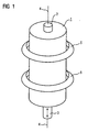
- the vacuum interrupter 1 shown in FIG. 1 has a substantially cylindrical outer contour.
- the first cylinder base protrudes a fixed first Switch contact piece 2 through.
- the second cylinder base protrudes a movable second switching contact piece 3rd therethrough.
- the first switching contact piece 2 and the second Switch contact piece 3 are coaxial on the cylinder axis 4 of Vacuum interrupter 1 arranged opposite.
- At the inside the vacuum interrupter 1 form the first switching contact piece. 2 and the second switching contact piece 3 from a switching path.
- Such a vacuum interrupter 1 can, for example, as Interrupter unit of a high voltage or medium voltage circuit breaker be used.
- Radial around the lateral surface the vacuum interrupter 1 circulating is an annular first shielding electrode 5 and an annular second shielding electrode 6 is arranged.
- the two shielding electrodes 5, 6 are on the vacuum interrupter 1, which an electrical device is supported.
- the positions of the arrangement of the shielding electrodes 5, 6 are further shielding electrodes, for example the end portions of the cylindrical vacuum interrupter. 1 locatable.
- the circular contour of the shielding electrodes 5, 6 are for the design of the shielding electrodes also other forms available, such as oval shapes or polygonal frame shapes.
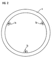
- FIG. 2 is a plan view of the first shielding electrode 5 is shown.
- the shielding electrode 5 has at its Inner radius three attachment points 7a, b, c on.
- the attachment points 7a, b, c each have the same constructive Build up.
- Of the Attachment point 7a is enlarged and detailed in FIG shown.
- the section shown in FIG the first shielding electrode 5 is in its cross section formed according to tubular, wherein along the lateral surface of the Pipe a slot 8 completely breaks the pipe wall. Through the slot 8 is a first edge portion in cross section 9 and a second edge portion 10 is formed. To the second edge portion 10, a first tongue 11 is arranged.
- the tongue 11 is during a casting process cohesively with the first shielding electrode 5 been connected.
- the tongue 11 extends in a first portion 11a into the slot 8 and extends in a second section 11b radially in the direction the center of the annular first shielding electrode 5.
- On the second section 11b are a plurality of locking lugs 12a, b, c, d arranged.
- the locking lugs 12a, b, c, d are on her base unilaterally on the second portion 11 b of first tongue 11 held.
- Each of the locking lugs 12a, b, c, d has a Deutschengreifung on.
- the locking lugs 12a, b, c, d form a Group of locking lugs, which spaced from each other are and form a circular peripheral contour. there they are spaced such that each of the locking lugs 12a, b, c, d elastically resiliently deformable at its free end is.
- the locking lugs 12a, b, c, d are through a circular recess a holder, which on the vacuum interrupter 1 is attached, Jerusalembar. While passing through there is a resilient deformation of the locking lugs, so that the extent formed by the locking lugs 12a, b, c, d during the passage of the opening is reduced.
- the opening dimensioned such that with reaching the Hintergreifung the locking lugs 12a, b, c, d, the locking lugs 12a, b, c, d in their starting position spring back and set the control electrode.
- the vacuum interrupter 1 has as a holder for the first shielding electrode 5 on a shell-side circumferential plate 16 with a circular outer contour.
- the sheet 16 has a plurality of openings 21a, b, c, in which the latching lugs of the attachment points 7a, b, c can be latched.
- slot-like recesses 22a, b, c are introduced into the body edge of the metal sheet 16. The recesses 22a, b, c allow the attachment points 7a, b, c to pass without stressing them mechanically.
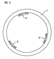
- FIG. 4 shows the second shielding electrode 6 in one Top view.
- the second shielding electrode 6 has three attachment points 7d, e, f.
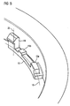
- One of the attachment points 7d of second shielding electrode 6 is shown in detail in FIG.
- the section of the second illustrated in FIG Shielding electrode 6 is designed as a solid circular ring.
- the attachment points 7d, e, f of the second shielding electrode 6 are radially inward with the second shield electrode 6 connected.
- Each of the attachment points 7d, e, f of the second shielding electrode 6 has a second one Tongue 13 up.
- the second tongue 13 is parallel to a Section of the annular second shielding 6th and has a longitudinal axis 19.
- the second tongue 13 At its free end points the second tongue 13 a further locking lug 14 with a vertical axis 20 on.
- the further locking lug 14 is substantially hook-shaped educated.
- the second tongue 13 a support surface 15a and a recessed support surface 15b on.
- the further locking lugs of the attachment points 7d, e, f of the second shielding electrode 6 are rigid Body edge latched. Due to the elongated design the second tongue 13, the support surface 15a are based on the rigid body edge and the second tongue 13 deformed at a latching the further locking lug 14, so that the further locking lug 14 fixed spring-loaded latched is.
- the recessed support surface 15b limited the deformation of the second tongue 13 during a latching operation.
- FIGS. 6 to 10 each show a cross section through Embodiments of Ablektroden.
- FIG. 6 shows that shown in FIGS. 2 and 3 Locking connection in assembled state.
- the vacuum interrupter 1 is a holder in the form of a rigid sheet 16 arranged circumferentially around the jacket.
- This rigid sheet 16 has recesses into which the groups latching lugs 12a, b, c, d are latched.
- FIG. 7 shows a variant of that shown in FIG Locking connection.
- the locking connection 7 shows a support element 17, against which the Support locking lugs in the assembled state spring elastic and are positioned so spring loaded.
- FIGS. 8 and 9 each show an embodiment variant of FIG in the figures 4 and 5 and described above locking connection in the assembled state.
- the figure shows 9 a solidly configured shielding electrode and the figure 8 a tubular shielding electrode with a Pipe wall breaking through slot.
- the local locking lugs grab each behind the edges of the rigid sheet metal 16. Due to the distribution of several locking lugs on the circumference of the rigid sheets 16 secure the various locking lugs each other from slipping (see Figure 4).
- FIG. 10 shows an alternative embodiment a catch.
- the local latch 18 is in each case to the both delimiting the slot in the tubular shield electrode Fixed edge portions.
- the local Locking lug 18 so elastic that a recess on the Body edge of the rigid plate 16 can be latched.
- 5 and 8 and 9 is in the embodiment variant according to 10 shows the position of the shielding electrode by the interaction more arranged on the circumference of the rigid plate 16 Positioned locking lugs. Furthermore, it can be provided to arrange a plurality of recesses on the detent 18 to the easily compensate the position of the shielding electrode.
- a simple adjustment of the position of a shielding electrode is allows when the latches several in Aufreastcardi behind behind one another or recesses exhibit.
Landscapes
- High-Tension Arc-Extinguishing Switches Without Spraying Means (AREA)
- Electrolytic Production Of Metals (AREA)
- Vessels, Lead-In Wires, Accessory Apparatuses For Cathode-Ray Tubes (AREA)
- Arc-Extinguishing Devices That Are Switches (AREA)
- Endoscopes (AREA)
- Transition And Organic Metals Composition Catalysts For Addition Polymerization (AREA)
- Radiation Pyrometers (AREA)
Description
- Figur 1
- eine perspektivische Ansicht einer Vakuumschaltröhre mit Abschirmelektroden, die
- Figur 2
- eine Draufsicht einer Abschirmelektrode in einer ersten Ausgestaltungsvariante, die
- Figur 3
- ein Detail einer Rastverbindung der Abschirmelektrode der ersten Ausgestaltungsvariante, die
- Figur 4
- eine Draufsicht einer zweiten Ausgestaltungsvariante einer Abschirmelektrode, die
- Figur 5
- ein Detail der Rastverbindung der zweiten Ausgestaltungsvariante einer Abschirmelektrode, die
- Figuren 6-10
- je einen Querschnitt durch eine Abschirmelektrode mit zugehörigen Rastverbindungen in ihren Einbaulagen und die
- Figur 11
- ein Ausgestaltungsbeispiel für eine Halterung.
Die Vakuumschaltröhre 1 weist als Halterung für die erste Abschirmelektrode 5 ein mantelseitig umlaufendes Blech 16 mit einer kreisrunden Außenkontur auf. Das Blech 16 weist mehrere Öffnungen 21a,b,c auf, in welche die Rastnasen der Befestigungspunkte 7a,b,c einrastbar sind. Um während einer Montage weitere Abschirmelektroden über das Blech bewegen zu können, sind in die Körperkante des Bleches 16 schlitzartige Ausnehmungen 22a,b,c eingebracht. Die Ausnehmungen 22a,b,c ermöglichen ein Passieren der Befestigungspunkte 7a,b,c, ohne diese mechanisch zu belasten.
Claims (7)
- Im Wesentlichen ringförmige Abschirmelektrode (6), welche mit einem elektrischen Schaltgerät (1) durch eine Rastverbindung verbindbar ist,
dadurch gekennzeichnet, dass
die Rastverbindung eine auf einer Zunge (13) angeordnete Rastnase (14) aufweist, wobei die Zunge (13) in Umfangsrichtung parallel zu einem Abschnitt der Abschirmelektrode (6) angeordnet ist. - Abschirmelektrode (6) nach Anspruch 1,
dadurch gekennzeichnet, dass
die Zunge (13) eine Längsachse und die Rastnase (14) eine Hochachse aufweist und die Längsachse senkrecht zur Hochachse angeordnet ist. - Abschirmelektrode (6) nach einem der Ansprüche 1 oder 2,
dadurch gekennzeichnet, dass
die Zunge (13) an der Abschirmelektrode befestigt ist. - Abschirmelektrode (6) nach einem der Ansprüche 1 bis 3,
dadurch gekennzeichnet, dass
die Abschirmelektrode (6) im Wesentlichen rohrförmig mit einem die Rohrwandung durchbrechenden Schlitz (8) ausgebildet ist. - Abschirmelektrode (6) nach Anspruch 4,
dadurch gekennzeichnet, dass
die Zunge (13) an einem der im Querschnitt der Abschirmelektrode den Schlitz (8) begrenzenden Randabschnitte der Abschirmelektrode (6) befestigt ist. - Abschirmelektrode (6) nach einem der Ansprüche 1 bis 5,
dadurch gekennzeichnet, dass
die Abschirmelektrode (6) ein Kunststoffformteil ist. - Abschirmelektrode (6) nach einem der Ansprüche 1 bis 6,
dadurch gekennzeichnet, dass
die Abschirmelektrode (6) an einer Vakuumschaltröhre (1) angeordnet ist.
Applications Claiming Priority (3)
| Application Number | Priority Date | Filing Date | Title |
|---|---|---|---|
| DE10229095 | 2002-06-25 | ||
| DE10229095A DE10229095B4 (de) | 2002-06-25 | 2002-06-25 | Abschirmelektrode |
| PCT/DE2003/001525 WO2004001783A1 (de) | 2002-06-25 | 2003-05-06 | Abschirmelektrode |
Publications (2)
| Publication Number | Publication Date |
|---|---|
| EP1516346A1 EP1516346A1 (de) | 2005-03-23 |
| EP1516346B1 true EP1516346B1 (de) | 2005-10-12 |
Family
ID=29795955
Family Applications (1)
| Application Number | Title | Priority Date | Filing Date |
|---|---|---|---|
| EP03729883A Expired - Lifetime EP1516346B1 (de) | 2002-06-25 | 2003-05-06 | Abschirmelektrode |
Country Status (6)
| Country | Link |
|---|---|
| EP (1) | EP1516346B1 (de) |
| JP (1) | JP2005531108A (de) |
| CN (1) | CN1320572C (de) |
| AT (1) | ATE306716T1 (de) |
| DE (2) | DE10229095B4 (de) |
| WO (1) | WO2004001783A1 (de) |
Families Citing this family (3)
| Publication number | Priority date | Publication date | Assignee | Title |
|---|---|---|---|---|
| DE112007000724B4 (de) * | 2006-03-27 | 2011-06-30 | Mitsubishi Electric Corp. | Schaltgerät und Verfahren zu dessen Herstellung |
| EP2715743B1 (de) | 2011-05-27 | 2020-03-04 | ABB Schweiz AG | Elektrische komponente für eine hochspannungsanlage |
| DE102017222941A1 (de) * | 2017-12-15 | 2019-06-19 | Siemens Aktiengesellschaft | Hochspannungsleistungsschalter und Verfahren zum elektromagnetischen Abschirmen einer Vakuumschaltröhre in einem Isolator |
Family Cites Families (10)
| Publication number | Priority date | Publication date | Assignee | Title |
|---|---|---|---|---|
| US3641384A (en) * | 1970-03-16 | 1972-02-08 | Hughes Aircraft Co | Switching device |
| DE2442405C3 (de) * | 1974-09-03 | 1981-04-09 | Siemens AG, 1000 Berlin und 8000 München | Steuerelektrode für Geräte und Anlagen der Hochspannungstechnik |
| DE8034443U1 (de) * | 1980-12-19 | 1981-05-27 | Siemens AG, 1000 Berlin und 8000 München | Freiluft-Hochspannungs-Leistungsschalter |
| DE4217697A1 (de) * | 1992-03-23 | 1993-09-30 | Siemens Ag | Elektrischer Hochspannungs-Leistungsschalter |
| DE19627208C1 (de) * | 1996-07-05 | 1997-10-16 | Siemens Ag | Schaltgerätekammer |
| DE19642517C2 (de) * | 1996-10-15 | 2001-02-08 | S. Siedle & Soehne,Telefon- Und Telegrafenwerke Stiftung & Co | Verbindungs-Einrichtung zum lösbaren Verbinden eines Oberteiles mit einem Unterteil eines Gehäuses für elektrische Geräte |
| DE19734090B4 (de) * | 1997-08-07 | 2005-01-20 | Hella Kgaa Hueck & Co. | Leuchte für Fahrzeuge mit einem Abschirmteil und mit einer Rastvorrichtung |
| DE29717489U1 (de) * | 1997-09-30 | 1999-01-28 | Siemens AG, 80333 München | Röhre zur Verwendung im Mittelspannungs- und Hochspannungsbereich |
| DE20106007U1 (de) * | 2001-04-05 | 2002-09-26 | Steelcase Werndl Aktiengesellschaft, 83026 Rosenheim | Abdeckvorrichtung |
| DE10118960C1 (de) * | 2001-04-10 | 2003-01-23 | Siemens Ag | Isoliergehäuse, insbesondere Gehäuse einer Schaltröhre eines Vakuumschalters, mit einer Halterung zur Positionierung einer Steuerelektrode |
-
2002
- 2002-06-25 DE DE10229095A patent/DE10229095B4/de not_active Expired - Fee Related
-
2003
- 2003-05-06 WO PCT/DE2003/001525 patent/WO2004001783A1/de not_active Ceased
- 2003-05-06 EP EP03729883A patent/EP1516346B1/de not_active Expired - Lifetime
- 2003-05-06 JP JP2004514541A patent/JP2005531108A/ja active Pending
- 2003-05-06 CN CNB038117495A patent/CN1320572C/zh not_active Expired - Fee Related
- 2003-05-06 DE DE50301377T patent/DE50301377D1/de not_active Expired - Lifetime
- 2003-05-06 AT AT03729883T patent/ATE306716T1/de not_active IP Right Cessation
Also Published As
| Publication number | Publication date |
|---|---|
| DE10229095A1 (de) | 2004-01-29 |
| JP2005531108A (ja) | 2005-10-13 |
| DE10229095B4 (de) | 2004-09-16 |
| CN1320572C (zh) | 2007-06-06 |
| ATE306716T1 (de) | 2005-10-15 |
| CN1656585A (zh) | 2005-08-17 |
| DE50301377D1 (de) | 2005-11-17 |
| WO2004001783A1 (de) | 2003-12-31 |
| EP1516346A1 (de) | 2005-03-23 |
Similar Documents
| Publication | Publication Date | Title |
|---|---|---|
| EP2188823B1 (de) | Isolierende schaltstange | |
| DE102015120921B4 (de) | Steckverbinder und Steckerverbinderanordnung | |
| DE102019111078A1 (de) | Befestigungsanordnung mit Dämpfungswirkung und Bauteilverbindung mit der Befestigungsanordnung | |
| DE102020200976A1 (de) | Abschirmfederhülse für Hochstromsteckverbindungen | |
| WO2003096366A1 (de) | Elektrisches schaltgerät mit einer kühleinrichtung | |
| EP0727797A1 (de) | Sicherheitsschalter | |
| EP1516346B1 (de) | Abschirmelektrode | |
| DE102008059308A1 (de) | Elektrische Trennwanddurchführung | |
| EP2390890B1 (de) | Schaltkammerisolationsanordnung für einen Leistungsschalter | |
| EP1686602B1 (de) | Düsenbefestigung für elektrisches Schaltgerät | |
| EP0621444A1 (de) | Schnellverschluss für Leuchteneinsätze | |
| DE102010035625A1 (de) | Elektrischer Schalter und Verfahren zum Montieren einer Schalteinheit eines elektrischen Schalters | |
| DE202021100335U1 (de) | Spannungswandler und elektrischer Schrank | |
| EP3686909A1 (de) | Elektroinstallationsgerät mit sockelaufsatz | |
| DE102023104652A1 (de) | Berührungsschutzabdeckung, Anschlussteil und Modulverbinder | |
| EP0722208A2 (de) | Anordnung zur Einbauhalterung von Elektro-Installationsgeräten | |
| DE2847084A1 (de) | Schloss fuer einlochbefestigung | |
| WO2005076317A2 (de) | Fahrzeugscheinwerferlampe | |
| DE102010017440A1 (de) | Kabeldurchführung für einen Durchbruch in einer Wandung | |
| EP3157772B1 (de) | Befestigungsanordnung | |
| EP1597742B1 (de) | Drehschalter mit schaltwelle für ein elektrogerät | |
| EP1514706A1 (de) | Rastverbindung von Gehäuseteilen | |
| EP3069361A1 (de) | Kontakteinheit | |
| DE19629204A1 (de) | Vakuumschaltkammer | |
| DE7517712U (de) | Steckdose |
Legal Events
| Date | Code | Title | Description |
|---|---|---|---|
| PUAI | Public reference made under article 153(3) epc to a published international application that has entered the european phase |
Free format text: ORIGINAL CODE: 0009012 |
|
| 17P | Request for examination filed |
Effective date: 20041026 |
|
| AK | Designated contracting states |
Kind code of ref document: A1 Designated state(s): AT BE BG CH CY CZ DE DK EE ES FI FR GB GR HU IE IT LI LU MC NL PT RO SE SI SK TR |
|
| GRAP | Despatch of communication of intention to grant a patent |
Free format text: ORIGINAL CODE: EPIDOSNIGR1 |
|
| GRAS | Grant fee paid |
Free format text: ORIGINAL CODE: EPIDOSNIGR3 |
|
| GRAA | (expected) grant |
Free format text: ORIGINAL CODE: 0009210 |
|
| AK | Designated contracting states |
Kind code of ref document: B1 Designated state(s): AT BE BG CH CY CZ DE DK EE ES FI FR GB GR HU IE IT LI LU MC NL PT RO SE SI SK TR |
|
| PG25 | Lapsed in a contracting state [announced via postgrant information from national office to epo] |
Ref country code: FI Free format text: LAPSE BECAUSE OF FAILURE TO SUBMIT A TRANSLATION OF THE DESCRIPTION OR TO PAY THE FEE WITHIN THE PRESCRIBED TIME-LIMIT Effective date: 20051012 Ref country code: NL Free format text: LAPSE BECAUSE OF FAILURE TO SUBMIT A TRANSLATION OF THE DESCRIPTION OR TO PAY THE FEE WITHIN THE PRESCRIBED TIME-LIMIT Effective date: 20051012 Ref country code: SI Free format text: LAPSE BECAUSE OF FAILURE TO SUBMIT A TRANSLATION OF THE DESCRIPTION OR TO PAY THE FEE WITHIN THE PRESCRIBED TIME-LIMIT Effective date: 20051012 Ref country code: IE Free format text: LAPSE BECAUSE OF FAILURE TO SUBMIT A TRANSLATION OF THE DESCRIPTION OR TO PAY THE FEE WITHIN THE PRESCRIBED TIME-LIMIT Effective date: 20051012 Ref country code: SK Free format text: LAPSE BECAUSE OF FAILURE TO SUBMIT A TRANSLATION OF THE DESCRIPTION OR TO PAY THE FEE WITHIN THE PRESCRIBED TIME-LIMIT Effective date: 20051012 Ref country code: CZ Free format text: LAPSE BECAUSE OF FAILURE TO SUBMIT A TRANSLATION OF THE DESCRIPTION OR TO PAY THE FEE WITHIN THE PRESCRIBED TIME-LIMIT Effective date: 20051012 Ref country code: GB Free format text: LAPSE BECAUSE OF FAILURE TO SUBMIT A TRANSLATION OF THE DESCRIPTION OR TO PAY THE FEE WITHIN THE PRESCRIBED TIME-LIMIT Effective date: 20051012 Ref country code: RO Free format text: LAPSE BECAUSE OF FAILURE TO SUBMIT A TRANSLATION OF THE DESCRIPTION OR TO PAY THE FEE WITHIN THE PRESCRIBED TIME-LIMIT Effective date: 20051012 |
|
| REG | Reference to a national code |
Ref country code: GB Ref legal event code: FG4D Free format text: NOT ENGLISH |
|
| REG | Reference to a national code |
Ref country code: CH Ref legal event code: EP |
|
| REG | Reference to a national code |
Ref country code: CH Ref legal event code: NV Representative=s name: SIEMENS SCHWEIZ AG |
|
| REG | Reference to a national code |
Ref country code: IE Ref legal event code: FG4D Free format text: LANGUAGE OF EP DOCUMENT: GERMAN |
|
| REF | Corresponds to: |
Ref document number: 50301377 Country of ref document: DE Date of ref document: 20051117 Kind code of ref document: P |
|
| ET | Fr: translation filed | ||
| REG | Reference to a national code |
Ref country code: SE Ref legal event code: TRGR |
|
| PG25 | Lapsed in a contracting state [announced via postgrant information from national office to epo] |
Ref country code: BG Free format text: LAPSE BECAUSE OF FAILURE TO SUBMIT A TRANSLATION OF THE DESCRIPTION OR TO PAY THE FEE WITHIN THE PRESCRIBED TIME-LIMIT Effective date: 20060112 Ref country code: GR Free format text: LAPSE BECAUSE OF FAILURE TO SUBMIT A TRANSLATION OF THE DESCRIPTION OR TO PAY THE FEE WITHIN THE PRESCRIBED TIME-LIMIT Effective date: 20060112 Ref country code: DK Free format text: LAPSE BECAUSE OF FAILURE TO SUBMIT A TRANSLATION OF THE DESCRIPTION OR TO PAY THE FEE WITHIN THE PRESCRIBED TIME-LIMIT Effective date: 20060112 |
|
| PG25 | Lapsed in a contracting state [announced via postgrant information from national office to epo] |
Ref country code: ES Free format text: LAPSE BECAUSE OF FAILURE TO SUBMIT A TRANSLATION OF THE DESCRIPTION OR TO PAY THE FEE WITHIN THE PRESCRIBED TIME-LIMIT Effective date: 20060123 |
|
| PG25 | Lapsed in a contracting state [announced via postgrant information from national office to epo] |
Ref country code: PT Free format text: LAPSE BECAUSE OF FAILURE TO SUBMIT A TRANSLATION OF THE DESCRIPTION OR TO PAY THE FEE WITHIN THE PRESCRIBED TIME-LIMIT Effective date: 20060313 |
|
| NLV1 | Nl: lapsed or annulled due to failure to fulfill the requirements of art. 29p and 29m of the patents act | ||
| PG25 | Lapsed in a contracting state [announced via postgrant information from national office to epo] |
Ref country code: HU Free format text: LAPSE BECAUSE OF FAILURE TO SUBMIT A TRANSLATION OF THE DESCRIPTION OR TO PAY THE FEE WITHIN THE PRESCRIBED TIME-LIMIT Effective date: 20060413 |
|
| PG25 | Lapsed in a contracting state [announced via postgrant information from national office to epo] |
Ref country code: AT Free format text: LAPSE BECAUSE OF NON-PAYMENT OF DUE FEES Effective date: 20060506 |
|
| GBV | Gb: ep patent (uk) treated as always having been void in accordance with gb section 77(7)/1977 [no translation filed] |
Effective date: 20051012 |
|
| REG | Reference to a national code |
Ref country code: IE Ref legal event code: FD4D |
|
| PG25 | Lapsed in a contracting state [announced via postgrant information from national office to epo] |
Ref country code: MC Free format text: LAPSE BECAUSE OF NON-PAYMENT OF DUE FEES Effective date: 20060531 Ref country code: BE Free format text: LAPSE BECAUSE OF NON-PAYMENT OF DUE FEES Effective date: 20060531 |
|
| PLBE | No opposition filed within time limit |
Free format text: ORIGINAL CODE: 0009261 |
|
| STAA | Information on the status of an ep patent application or granted ep patent |
Free format text: STATUS: NO OPPOSITION FILED WITHIN TIME LIMIT |
|
| 26N | No opposition filed |
Effective date: 20060713 |
|
| BERE | Be: lapsed |
Owner name: SIEMENS A.G. Effective date: 20060531 |
|
| PG25 | Lapsed in a contracting state [announced via postgrant information from national office to epo] |
Ref country code: EE Free format text: LAPSE BECAUSE OF FAILURE TO SUBMIT A TRANSLATION OF THE DESCRIPTION OR TO PAY THE FEE WITHIN THE PRESCRIBED TIME-LIMIT Effective date: 20051012 |
|
| PG25 | Lapsed in a contracting state [announced via postgrant information from national office to epo] |
Ref country code: TR Free format text: LAPSE BECAUSE OF FAILURE TO SUBMIT A TRANSLATION OF THE DESCRIPTION OR TO PAY THE FEE WITHIN THE PRESCRIBED TIME-LIMIT Effective date: 20051012 Ref country code: LU Free format text: LAPSE BECAUSE OF NON-PAYMENT OF DUE FEES Effective date: 20060506 |
|
| PG25 | Lapsed in a contracting state [announced via postgrant information from national office to epo] |
Ref country code: CY Free format text: LAPSE BECAUSE OF FAILURE TO SUBMIT A TRANSLATION OF THE DESCRIPTION OR TO PAY THE FEE WITHIN THE PRESCRIBED TIME-LIMIT Effective date: 20051012 |
|
| REG | Reference to a national code |
Ref country code: CH Ref legal event code: PCAR Free format text: SIEMENS SCHWEIZ AG;INTELLECTUAL PROPERTY FREILAGERSTRASSE 40;8047 ZUERICH (CH) |
|
| PGFP | Annual fee paid to national office [announced via postgrant information from national office to epo] |
Ref country code: SE Payment date: 20130507 Year of fee payment: 11 |
|
| PGFP | Annual fee paid to national office [announced via postgrant information from national office to epo] |
Ref country code: FR Payment date: 20130618 Year of fee payment: 11 Ref country code: IT Payment date: 20130528 Year of fee payment: 11 |
|
| PGFP | Annual fee paid to national office [announced via postgrant information from national office to epo] |
Ref country code: CH Payment date: 20130812 Year of fee payment: 11 Ref country code: DE Payment date: 20130719 Year of fee payment: 11 |
|
| REG | Reference to a national code |
Ref country code: DE Ref legal event code: R119 Ref document number: 50301377 Country of ref document: DE |
|
| REG | Reference to a national code |
Ref country code: CH Ref legal event code: PL |
|
| PG25 | Lapsed in a contracting state [announced via postgrant information from national office to epo] |
Ref country code: CH Free format text: LAPSE BECAUSE OF NON-PAYMENT OF DUE FEES Effective date: 20140531 Ref country code: LI Free format text: LAPSE BECAUSE OF NON-PAYMENT OF DUE FEES Effective date: 20140531 Ref country code: SE Free format text: LAPSE BECAUSE OF NON-PAYMENT OF DUE FEES Effective date: 20140507 |
|
| REG | Reference to a national code |
Ref country code: SE Ref legal event code: EUG |
|
| REG | Reference to a national code |
Ref country code: DE Ref legal event code: R119 Ref document number: 50301377 Country of ref document: DE Effective date: 20141202 |
|
| REG | Reference to a national code |
Ref country code: FR Ref legal event code: ST Effective date: 20150130 |
|
| PG25 | Lapsed in a contracting state [announced via postgrant information from national office to epo] |
Ref country code: DE Free format text: LAPSE BECAUSE OF NON-PAYMENT OF DUE FEES Effective date: 20141202 Ref country code: IT Free format text: LAPSE BECAUSE OF NON-PAYMENT OF DUE FEES Effective date: 20140506 |
|
| PG25 | Lapsed in a contracting state [announced via postgrant information from national office to epo] |
Ref country code: FR Free format text: LAPSE BECAUSE OF NON-PAYMENT OF DUE FEES Effective date: 20140602 |